1
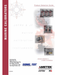
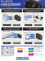
Temp/Humidity Measurements for Internal
Sorting Mechanism in Printers
Alternate Logging Device for Fuel-cell
Flow Measurement & Testing
Fuel
Built-in to the GL820
Expansion Terminal
GL820
Fuel Flow Rate
Temp
Temp
Humidity
GL820
Copy Machine
PC
Fuel Cell
Evaluation Tester
Target Industry:
Electronics/Business Machines
Target Testing Environment:
R&D
Analysis of Temperature & Humidity
Levels Inside Multi-decked Trains
Railway Vehicle
Target Industry:
Electronics & Battery
Flow & Temperature Measurements
for Water Heater Tanks
Water Heater Tank
Temp • Humidity
Control System
Temp • Humidity
Voltage
Temp • Humidity
Temp
GL820
Target Industry:
Transportation
MAX
10ms*1
Sampling
Up to
200*2
ch
type
A/D Converter
LAN
USB
USB Memory
Target Testing Environment:
R&D
Target Testing Environment:
Maintenance & Inspection
Built-in
2GB Flash
Memory
5.7 inch
TFT LCD
Display
*1: Maximum sampling is achieved only when 1 channel is being used.
*2: The standard configuration has 20 analog input channels.
Voltage
Logic
GL820
Target Industry:
Utilities: Gas, Water, Electric
20 mV to 50 V
4 channels*3
Temp
Humidity
Pulse
Target Testing Environment:
Maintenance & Inspection
Thermocouple types:
K, J, E, T, R, S, B, N, W (WRe5-26)
RTD types: Pt100 (IEC751), JPt100
(JIS), Pt1000 (IEC751)
0 to 100% RH using the optional
humidity sensor (B-530 option)
4 channels*3
Accumulating, Instant or RPM count
*3: Select either Pulse input or Logic input, and use the optional Input / Output cable (B-513 option).
GL820 main unit specifications
Item
Number of analog input channels
External input Input *8
output
Output *8
Sampling interval
Time scale
Trigger
Action
function
Source
Combination
Condition
Alarm function Detecting method
Condition
Alarm output *8
Accumulating count
mode
Pulse input
function *8
Calculation
function
Search function
Analog input specifications
Description
20 ch, Expandable up to 200 ch by unit of 20 ch
Trigger or Sampling input 1 ch, Logic or Pulse input 4 ch
Alarm output 4 ch
10 ms to 1 h (in 10ms to 50ms, voltage only and limited channel), External
1 sec to 24 hour /division
Start or stop capturing data by the triggerr
Start: Off, Input signal, Alarm, External *8, Clock, Week or Time
Stop: Off, Input signal, Alarm, External *8, Clock, Week or Time
OR or AND condition at the level of signal or edge of signal
Analog: Rising, Falling, Window-in, Window-out
Pulse: Rising, Falling, Window-in, Window-out
Logic: Rising, Falling
Level or edge of signal
Analog: Rising, Falling, Window-in, Window-out
Pulse: Rising, Falling, Window-in, Window-out
Logic: Rising, Falling
Counting the number of pulses per sampling interval
Range: 50, 500, 5 k, 50 k, 500 k, 5 M, 50 M, 500 M counts/F.S.
Rotation count (RPM)
mode
Counting the number of pulses per second and then it is converted to RPM
Range: 50 rpm, 500 rpm, 5 krpm, 50 krpm, 500 krpm, 5 Mrpm, 50 Mrpm, 500 Mrpm /F.S.
Max. input pulse rate
Between channels
Statistical
50 k pulses/sec or 50k counts per sampling interval (16 bits counter is used)
Addition, Subtraction, Multiplication and Division for analog input
Select two calculations from Average, Peak, Max., Min., RMS
Search for analog signal levels, values of logic or pulse or alarm point
in captured data
Captured data
Others
Ring capturing mode
Data saving
function
USB memory device emulation
Engineering scale function
Display
Ethernet (10 BASE-T/100 BASE-TX), USB (Full speed)
Built-in Flash memory (2 giga-bytes), USB memory device *9
Direct saving of data into built-in Flash memory or USB memory device
Setting conditions, Screen copy
Function: ON/OFF, Number of capturing point: 1000 to 2000000 (size of the
capture data will be limited to 1/3 of available memory when in Ring Mode)
USB Memory emulation mode (Transfer or delete the file in built-in memory)
Set based on the reference point of the scaled output and input signal for each
channel (Voltage measurement: four points are necessary to scale the output,
Temperature measurement: two points are necessary to scale the output).
Size
Formats
Operating environment
5.7 inch TFT color LCD (VGA: 640 x 480 dots)
Waveform + Digital, Waveform only, Calculation + Digital, Expanded digital
0 to 45 °C, 5 to 85 %RH
(When operating with battery pack 0 to 40 °C, charging battery 15 to 35 °C)
Power source
AC adapter (100 to 240 V, 50/60 Hz),
DC power (8.5 to 24 V DC, max. 26.4 V) *10, Battery pack *10
Power consumption
32 VA or lower
(when operating with AC adapter, displaying LCD, charging battery pack)
Software specifications
Item
Supported OS
Functions
GL820 settings control
Controlled units
Captured data
Displayed information
Display modes
Warning functions
File format conversions
Report functions
Description
Windows XP / Vista / 7 (32 bits and 64 bits edition)
Control GL820, Real-time data capture, Replay data, Data format conversion
Input settings, Memory settings, Alarm settings, Trigger settings
Up to 10 units or 500 channels
Transfers data in real-time (in binary or CSV format), saved data in GL820 or the USB memory
Analog waveforms, Logic waveforms, Pulse waveforms, Digital values
Y-T waveforms, Digital values, Report, X-Y graph (specified period of data, data reply only)
Sends E-mail to the specified address when the alarms occur
Converts the specified period data or all data to the CSV format (thinning function is available)
Creates the daily or monthly report automatically (can also export directly to Excel)
Standard accessories
Item
AC adapter
CD-ROM
Quick Start Guide
Filter
Measurement Voltage
accuracy *11
Temperature
Description
100 to 240 V AC, 50 / 60 Hz (with specified type of power cord)
User’s manual (PDF format), Application software
Distributed By:
Signal Test, Inc
1529 Santiago Ridge Way
San Diego, CA 92154
Tel. 1-619-575-1577 USA
www.SignalTestInc.com
[email protected]
Description
Screw terminal (M3 screw)
Scans by the photo-MOS-relay, all channels isolated, balanced input
20, 50, 100, 200, 500 mV, 1, 2, 5, 10, 20, 50 V, and 1-5 V/F.S.
Thermocouple: K, J, E, T, R, S, B, N, and W (WRe5-26)
Resistance Temperature Detectors (RTDs): Pt100, JPt100(JIS), Pt1000(IEC751)
0 to 100%
(using humidity sensor (B-530 optional), power is supplied to only one sensor)
Off, 2, 5, 10, 20, 40 (moving average in selected number)
0.1 % of F.S.
Thermocouple Measurement range
0 °C ≤ TS ≤ 100 °C
100 °C < TS ≤ 300 °C
R/S
R: 300 °C < TS ≤ 1600 °C
S: 300 °C < TS ≤ 1760 °C
400 °C ≤ TS ≤ 600 °C
600 °C < TS ≤ 1820 °C
B
-200 °C ≤ TS ≤ -100 °C
-100 °C < TS ≤ 1370 °C
-200 °C ≤ TS ≤ -100 °C
-100 °C < TS ≤ 800 °C
K
E
-200 °C ≤ TS ≤ -100 °C
-100 °C < TS ≤ 400 °C
T
J
N
W
RTD
Pt100
JPt100
Pt1000
A/D Converter
Between + / - terminal
Maximum
input voltage Between channels
Between channel / GND
Between channels
Withstand
voltage
Between channel(-)/ GND
*8
*9
Measurement accuracy
± 5.2 °C
± 3.0 °C
± (0.05 % of reading + 2.0 °C)
± (0.05 % of reading + 2.0 °C)
± 3.5 °C
± (0.05 % of reading + 2.0 °C)
± (0.05 % of reading + 2.0 °C)
± (0.05 % of reading + 1.0 °C)
± (0.05 % of reading + 2.0 °C)
± (0.05 % of reading + 1.0 °C)
± (0.1 % of reading + 1.5 °C)
± (0.1 % of reading + 0.5 °C)
± 2.7 °C
± 1.7 °C
± (0.05 % of reading + 1.0 °C)
± (0.1 % of reading + 1.0 °C)
± (0.1 % of reading + 1.5 °C)
Reference Junction Compensation (R.J.C.): ±0.5 °C
Measurement accuracy
Measurement range
-200 °C to 850 °C (FS = 1050 °C) ±1.0 °C
±0.8 °C
-200 °C to 500 °C (FS = 700 °C)
-200 °C ≤ TS ≤ -100 °C
-100 °C < TS ≤ 100 °C
100 °C < TS ≤ 1100 °C
0 °C ≤ TS ≤ 1300 °C
0 °C ≤ TS ≤ 2000 °C
±0.8 °C
-200 °C to 500 °C (FS = 700 °C)
ΣΔ type, 16 bits (effective resolution: 1/40000 of measuring full range)
60 V p-p
60 V p-p
60 V p-p
350 V p-p (1 minute)
350 V p-p (1 minute)
: Logic alarm cable (B-513) option is required.
Input signal of External sampling, Logic, Pulse; Maximum voltage: 24 V, Threshold: approx. 2.5 V, Hysteresis: approx. 0.5 V
: Size of the USB memory device is unlimited. Maximum file size is limited to 2GB.
DC drive cable (B-514) or battery pack (B-517) option is required.
Subject to the following conditions;
• Room Temperature is 23°C ±5°C.
• When 30 minutes or more have elapsed after power was turned on.
• Filter is set to 10.
• Sampling rate is set to 1s with 20 channels.
• GND terminal is connected to ground.
*10:
*11:
approx. 232 x 152 x 50 mm
approx. 900 g (Excluding AC adapter and battery pack)
Weight
Humidity
4 channels, Output type: Open collector (pulled-up to 5 V by resistor 10 kΩ)
Accumulating the number of pulses from the start of measurement
Range: 50, 500, 5 k, 50 k, 500 k, 5 M, 50 M, 500 M counts/F.S.
Instant count mode
Interface to PC
Storage device
Item
Type of input terminal
Input method
Measurement Voltage
range
Temperature
Quantity
1 set
1 piece
1 copy
Options and accessories
Item
Logic alarm cable
DC drive cable
Battery pack
Humidity sensor *12
Model number
B-513
B-514
B-517
B-530
Remarks
2 m long (no clip on end of cable)
2 m long (no clip on end of cable)
1 piece (7.4 V 2200 mAh, 17Wh)
3 m long (with power plug)
Terminal base, cable
Terminal base, terminal unit (20 ch), fixing plate
Extension terminal base kit B-537
20 ch extension terminal set B-538
Logic alarm cable
(B-513)
Extension terminal
base kit (B-537)
*12:
DC drive cable
(B-514)
Battery pack
(B-517)
20ch extension
terminal set (B-538)
Operating environment: -25°C to 80°C
www.graphtecamerica.com/instruments
Humidity sensor
(B-530) * 12