1
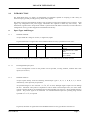
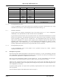
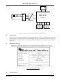
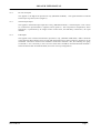
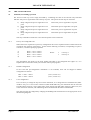
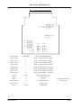
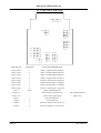
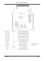
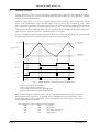
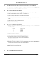
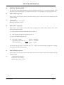
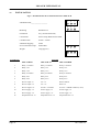
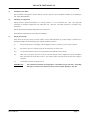
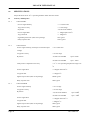
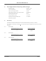
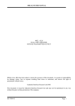
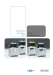
2002-ALM USER MANUAL
2002 - ALM
DUAL TRIP AMPLIFIER
Whilst every effort has been taken to ensure the accuracy of this document, we accept no
responsibility for damage, injury, loss or expense resulting from errors or omissions, and reserve
the right of amendment without notice.
Industrial Interface Research Ltd - 2002
This document is issued by Industrial Interface Research Ltd and may not be reproduced in any way
without the prior written permission of the company.
IIG-9504-04
Page 1
2002-ALM USER MANUAL
CONTENTS
PAGE
1.0
INTRODUCTION
3
2.0
UNPACKING
3.0
CONNECTIONS
7
4.0
TRIP CONFIGURATION
9
5.0
INPUT RECONFIGURATION AND CALIBRATION (APPLIES TO RE-
16
6
CONFIGURABLE UNITS ONLY)
6.0
SETTING TRIP POINTS
18
7.0
INSTALLATION
19
8.0
SPECIFICATIONS
21
Page 2
IIG-9504-04
2002-ALM USER MANUAL
1.0
INTRODUCTION
The 2002-ALM range is a family of configurable trip amplifiers capable of accepting a wide variety of
electrical input types and providing two trip action relay outputs.
The family comprises three different products each accepting an input from a different type of sensor. Input
signal, trip configuration and power supply information are required to define any unit exactly. This
information, together with a unique serial number is printed on the side label of each unit; records of the exact
configuration of every product shipped are maintained at the factory.
1.1
1.1.1
Input Types And Ranges:
IIR 2002-ALM-HL
Accepts either DC voltage or current (i.e. high level) inputs.
In general the limits on signals that can be handled with the accuracy specified in section 8 are:
FULL SCALE INPUT
DC CURRENT
MIN
50µA
MAX
10A
MIN SPAN
50% FULL SCALE
NOTES
MAX VOLTAGE DROP =
0.33V
DC VOLTAGE
100mV
300V
50% FULL SCALE
10K ohm ≤ R in ≤ 10M
ohm
USE 2002-TC FOR
Vin<100mV
All the standard process ranges such as 0-10mA, 4-20mA, 0-20mA, 1-5V and 0-10V are of course covered.
1.1.1.1
Reconfigurable input option
A user reconfigurable version of the product can be specified, covering 0-20mA, 4-20mA and 0-10V
inputs (see section 5).
1.1.2
IIR 2002-ALM-TC
Accepts inputs directly from the following thermocouple types: J, K, N, T, R, B, E, U, L and S.
Alternatively a mV input may be specified.
All specified ranges are zero referred - i.e. 0°F, 0°C or 0mV, although negative inputs will not damage
the unit. Automatic cold junction compensation will be fitted to thermocouple units, for which either
upscale or downscale drive on break detection are link selectable (see section 4) - factory default setting is
upscale. The process signal is not linearised. For standard thermocouples the operating range will be
specified in °C or °F, as required.
In general, the limits on signals that can be handled with the accuracy specified in section 8 are:
IIG-9504-04
Page 3
2002-ALM USER MANUAL
FULL SCALE INPUT
mV
J (L)
MIN
4mV
MAX
100mV
80°C
1200°C
K
100°C
1372°C
T (u)
95°C
400°C
E
1.1.2.1
65°C
1000°C
N
150°C
1300°C
R
460°C
1768°C
S
480°C
1760°C
B
910°C
1820°C
NOTES
COLD JUNCTION COMPENSATION WILL
NOT BE FITTED
Reconfigurable input option.
A user reconfigurable version of the product can be specified covering any 4 thermocouple type / range
combinations (see section 5). Note: all ranges must be in the same units (e.g. °C).
1.1.3
IIR 2002-ALM-RTD
Accepts inputs from resistance thermometers such as the PT100 type in 2 or 3 wire configuration.
Additionally 2 wire potentiometers less than 1K ohm can be accommodated.
In general the measured resistance can be anywhere between zero and 1Kohm and standard curves such as
PT100 can be linearised. The minimum span must be 10 ohm for the accuracy specified in section 8,
which corresponds to roughly 30°C for a PT100 sensor. For standard RTD sensor types, the operating
range will be specified in °C and the process signal will be linearised; otherwise the range will be
specified in ohms without linearisation. 2 or 3 wire connection is link selectable (see section 4) - factory
default setting is 3 wire. Downscale drive on wire break detection is standard - upscale drive can be
specially requested from the factory but is only possible with a 2 wire connection.
1.1.3.1
Reconfigurable input option
A user reconfigurable version of the product can be specified covering any 4 RTD / resistance
combinations (see section 5).
1.2
Description of operation
The input stage of the 2002 ALM produces an internal process signal of 0 - 1V DC corresponding to the input
span. This signal can be measured between terminals 12 and 9 of the HL unit and may be available for the
TC and RTD units, dependent on configuration (see section 4).
The trip set point potentiometers produce set point signals of 0 - 1V DC corresponding to the input span.
These signals can be measured between terminal 12 and the relevant front panel brass terminal.
Internal circuitry compares the process signal with each of the set point levels and changes the state of the
output relays and indicator LED’s as the signal passes through the set point, the exact action being factory or
user configurable (see section 4).
A hysteresis band (typically 1% of span unless specifically requested) below each set point ensures chatterfree trip operation.
A block schematic diagram of the 2002-ALM is shown in Figure 1.
Page 4
IIG-9504-04
2002-ALM USER MANUAL
+
11
10
7
I/V
2002-ALM
t/c
8
RTD
Trip Amplifier
9
Input Isolation
1
2
Relay 1
3
4
5
6
Relay 2
FIG. 1 - BLOCK SCHEMATIC DIAGRAM FOR THE IIR-2002-ALM TRIP AMPLIFIER
2.0
UNPACKING
Please inspect the instrument carefully for signs of shipping damage. The unit is packaged to give maximum
protection but we can not guarantee that undue mishandling will not have damaged the instrument. In the case
of this unlikely event, please contact your supplier immediately and retain the packaging for our subsequent
inspection.
2.1
Checking the Unit Type
Each unit has a unique serial number label on which full details of the configuration are given (see
Figure 2 for example). These details should be checked to ensure conformance with your requirement.
Fig. 2 - Serial Number Label
3.0
CONNECTIONS
IIG-9504-04
Page 5
2002-ALM USER MANUAL
This section details the instrument connection information. These details are also shown on the connections
side label on each unit (see figure 3).
Fig. 3 - 2002-ALM Connection Details
3.1
Power Supply
The power supply is connected into terminals 10 (negative) and 11 (positive). The supply voltage is indicated
on the serial number label (Figure 2)
APPLICATION OF VOLTAGES HIGHER THAN THAT STATED FOR THE SUPPLY MAY CAUSE
DAMAGE TO THE INSTRUMENT.
3.2
Sensor Connections
All sensor connections are made to terminals numbered 7, 8 and 9 on the instrument.
The inputs are connected as described below.
3.2.1
DC Voltage Inputs
This applies to the high level input device only (IIR-2002-ALM-HL). The signal should be connected
between pins 8 (positive) and 7(negative).
Page 6
IIG-9504-04
2002-ALM USER MANUAL
3.2.2
DC Current Inputs
This applies to the high-level input device only (IIR-2002-ALM-HL). The signal should be connected
between pins 8 (positive) and 7 (negative).
3.2.3
Thermocouple Inputs
This applies to the thermocouple input device only, (IIR-2002-ALM-TC). Thermocouples or mV sources
are connected to input terminals 7 (negative) and 8 (positive). The cold junction compensation, where
appropriate, is performed by an integral sensor located close, and thermally connected to, the input
terminal.
3.2.4
RTD Inputs
This applies to the resistance thermometer input device only, (IIR-2002-ALM-RTD). RTD’s should be
connected using three identical wires in order that measurement errors due to lead wire resistances can be
eliminated. The sensor common wires should be connected to terminals 7 & 9, the remaining wire going
to terminal 8. If it is necessary to use a two wire sensor then it should be connected between terminals 7
and 8 and internal link 22 should be fitted (see section 4.0 Trip Configuration).
IIG-9504-04
Page 7
2002-ALM USER MANUAL
4.0
TRIP CONFIGURATION
4.1
Standard (non latching) operation
The action of each trip can be simply described by considering the state of the relevant relay and LED
indicator with process signal either side of the trip set point. The options for each trip are as follows:
a)
b)
c)
d)
Relay energised for process signal above set
point
Relay energised for process signal above set
point
Relay energised for process signal below set
point
Relay energised for process signal below set
point
LED on for process signal above set point
LED off for process signal above set point
LED on for process signal below set point
LED off for process signal below set point
Thus any combination of fail safe or non fail safe options can be catered for.
4.1.2
Factory Pre-Configured Units
Where the unit is required for a preset trip configuration this can be requested at time of order and will be
carried out free of charge at the factory. In this case the following convention, corresponding to option a
to d above, is used for specifying operation:
a)
b)
c)
d)
RLY x > SP x < LED x
RLY x > SP x > LED x
RLY x < SP x > LED x
RLY x < SP x < LED x
Where
x
x
= 1 for trip 1
= 2 for trip 2
This information will appear on the serial number side label on pre-configured units (figure 2). It is
helpful if this convention is used by the customer when specifying units.
4.1.3
Default Configuration
In the event that pre-configuration information is not available, units will be shipped in default
configuration as follows:
RLY 1 > SP 1 < LED 1
RLY 2 < SP 2 > LED 2
4.1.4
(case a, section 4.1)
(case c, section 4.1)
User Configuration
If it is necessary to change the trip action of the instrument, or to change the wire break detection (2002ALM-TC only) or 2/3 wire sensor connection (2002-ALM-RTD only), the instrument must be removed
from the plastic enclosure. This is achieved by gently prising apart both sides of the grey plastic box, next
to the connection terminals, and withdrawing the circuit board with the black terminal blocks.
The units may then be configured by changing the handbag links with reference to the appropriate one of
the following diagrams:
Page 8
IIG-9504-04
2002-ALM USER MANUAL
Fig. 4 - 2002-ALM-HL Link Settings
1
1
L13
1
L8
L7
1
1
2
2
L6
L5
1
1
2
2
L1 L2
2
2
2
L12
L11
L10
L3 L4
1
1
1
1
2
2
2
2
L9
LINK SET NO
POSITION
FUNCTION DESCRIPTION
Links 1 and 2
1
Relay 1 energised Above Setpoint
Links 1 and 2
2
Relay 1 energised Below Setpoint
Links 3 and 4
1
Relay 2 energised Below Setpoint
Links 3 and 4
2
Relay 2 energised Above Setpoint
Links 5 and 6
1
LED2 on when Relay 2 energised
Links 5 and 6
2
LED2 Off when Relay 2 energised
Links 7 and 8
1
LED1 Off when Relay 1 energised
Links 7 and 8
2
LED1 On when Relay 1 energised
Link 9
fitted
Relay Latching Function
Link 10
1
0-20mA/0-10v
Link 10
2
4-20mA
Links 11 and 12
1
Current (mA) Input
}
Links 11 and 12
2
Voltage Input
}
Link 13
fitted
0-20mA Input
}
IIG-9504-04
}
} Reconfigurable Input
Option Only
Page 9
2002-ALM USER MANUAL
Fig. 5 - 2002-ALM-TC Link Settings
1
L20
L18
2
1
2
L10
L11
L12
L13
L14
L15
L16
L17
L8
L7
1
1
2
2
L6
L5
1
1
2
2
L1 L2
L3 L4
1
1
1
1
2
2
2
2
L9
LINK SET NO
POSITION
FUNCTION DESCRIPTION
Links 1 and 2
1
Relay 1 energised Above Setpoint
Links 1 and 2
2
Relay 1 energised Below Setpoint
Links 3 and 4
1
Relay 2 energised Below Setpoint
Links 3 and 4
2
Relay 2 energised Above Setpoint
Links 5 and 6
1
LED2 On when Relay 2 energised
Links 5 and 6
2
LED2 Off when Relay 2 energised
Links 7 and 8
1
LED1 Off when Relay 1 energised
Links 7 and 8
2
LED1 On when Relay 1 energised
Link 9
fitted
Relay Latching Function
Links 10-13
Thermocouple Type Selection
Links 14-17
Thermocouple Input Range
Link 18
1
Downscale Burnout
Link 18
2
Upscale Burnout
Link 20
1
Terminal 9 measures Process (0-1V)
Link 20
2
Terminal 9 used for t/c screen conn.
Page 10
}Reconfigurable Input
}
Option Only
IIG-9504-04
2002-ALM USER MANUAL
Fig. 6 - 2002-ALM-RTD Link Settings
L23
1
2
L19
L18
L10
L11
L12
L13
L20
L21
L22
L14
L15
L16
L17
L8
L7
1
1
2
2
L6
L5
1
1
2
2
L1 L2
L3 L4
1
1
1
1
2
2
2
2
L9
LINK SET NO
POSITION
FUNCTION DESCRIPTION
Links 1 and 2
1
Relay 1 energised Above Setpoint
Links 1 and 2
2
Relay 1 energised Below Setpoint
Links 3 and 4
1
Relay 2 energised Below Setpoint
Links 3 and 4
2
Relay 2 energised Above Setpoint
Links 5 and 6
1
LED2 On when Relay 2 energised
Links 5 and 6
2
LED2 Off when Relay 2 energised
Links 7 and 8
1
LED1 Off when Relay 1 energised
Links 7 and 8
2
LED1 On when Relay 1 energised
Link 9
fitted
Relay Latching Function
Links 10-13
RTD Range Zero Selection
}
Links 14-17
RTD Range Span Selection
} Reconfigurable Input
Links 18-21
RTD Range Gain Selection
}
Link 22
fitted
For 2-wire RTD Operation
Link 22
not fitted
For 3-wire RTD Operation
Link 23
1
Process O/P on terminal 9 (0-1V)
Link 23
2
3-wire connection to terminal 9
IIG-9504-04
Option only
Page 11
2002-ALM USER MANUAL
4.2
Latching Operation
Latching operation of relay 1 can be achieved by connecting link 9. Note that, where latching operation is
specified, trip set point 2 is used to set the unlatch threshold such that Relay 2 is not independent. Latching
operation is not possible with relay 2.
With Link 9 fitted, Relay 1 can be set to energise when the process signal rises above or falls below trip set
point 1, in the normal fashion. At the same time LED 1 can be set to be on above or below set point 1. Once
relay 1 has become energised it will remain energised so long as either the initial condition which caused the
trip is sustained, or whilst relay 2 is de-energised, or both. i.e. relay 1 can only be latched whilst relay 2 is deenergised and can only be unlatched whilst relay 2 is energised. (Note that LED1 denotes whether the process
signal is above or below trip set point 1, not whether relay 1 is energised.)
By way of example the latching mode of operation is likely to be used to maintain the process signal between
an upper and a lower limit (for instance tank level control) as shown in Figure 7:
SET POINT 2
}
HYSTERESIS
BAND
}
HYSTERESIS
BAND
PROCESS SIGNAL
SET POINT 1
EN
RELAY 1
EN
RELAY 2
ON
LED 1
ON
LED 2
Fig. 7 - Timing Diagram - Latching Operation Of 2002-ALM
Trip 1 is set to option d) (section 4.1)
Trip 2 is set to option b) (section 4.1)
Trip set point 1 is set to the lower allowable limit
Trip set point 2 is set to the upper allowable limit
When the process signal is below set point 1 relay 1 is energised (latched) and will remain energised
until the signal reaches set point 2. At this point relay 1 is unlatched (by relay 2 energising). As the
process signal reduces relay 2 de-energises. As the signal falls below set point 1 relay 1 is energised
(latched) again and the cycle repeats.
The LEDs can be used to indicate the status as follows:
LED1
LED2
STATUS
OFF
OFF
Power Fail
OFF
ON
At or below bottom unit
ON
OFF
At or above top limit
ON
ON
Within limits
Page 12
IIG-9504-04
2002-ALM USER MANUAL
5.0
INPUT RECONFIGURATION (RECONFIGURABLE UNITS ONLY) AND CALIBRATION
If the 2002-ALM has a reconfigurable input option reconfiguration can be carried out by changing handbag
links and, for greatest accuracy, recalibrating the 0-1V process signal.
5.1
2002-ALM-HL Reconfiguration and Calibration
(i)
Referring to 2002-ALM-HL link setting diagram (figure 4), set links 10
(ii)
Connect voltmeter between connector terminals 12 (-ve) and 9 (+ve)
iii)
Connect a current or voltage source as appropriate to input terminals 7
(-ve) and 8 (+ve)
through 13 as required
(iv) Adjust VR4 to give 0.00V on voltmeter at zero scale for 4-20mA range only - zero is automatic for other
ranges
(v)
Adjust VR3 to give 1.00V on voltmeter at full scale
(vi) Repeat (iv) and (v) as necessary.
5.2
2002-ALM-TC Reconfiguration and Calibration
(i)
Referring to 2002-ALM-TC link setting diagram (figure 5), select range 1, 2, 3 or 4, as detailed on unit
side label, as follows:
RANGE
1
2
3
4
(ii)
LINKS FITTED
13 and 17
12 and 16
11 and 15
10 and 14
Make sure that link 20 is in position 1
(iii) Connect voltmeter between connector terminals 12 (-ve) and 9 (+ve)
(iv) Ensuring that the cold junction compensation temperature is equal to
the 2002-TC terminal temperature, connect a thermocouple simulator
to terminals 7 (-ve) and 8 (+ve)
(v) Adjust VR4 to give 1.00V on voltmeter at full scale
(vi) Adjust VR3 to give 0.00V on voltmeter at zero scale (NB ensure that voltage increases with small input to
check that unit is in its linear range - this signal will not go negative)
(vii) Repeat (v) and (vi) as necessary
(viii) Replace link 20 if screen connection is used.
5.3
2002-ALM-RTD Reconfiguration and Calibration
IIG-9504-04
Page 13
2002-ALM USER MANUAL
(i)
Referring to the 2002-ALM-RTD link setting diagram (figure 6), select range 1, 2, 3 or 4, as detailed on
unit side label, as follows:
RANGE
1
2
3
4
(ii)
LINKS FITTED
13, 17, 21
12, 16, 20
11, 15, 19
10, 14, 18
Make sure that link 23 is in position 1 and that link 22 is fitted
(iii) Connect voltmeter between connector terminals 12 (-ve) and 9 (+ve)
(iv) Ensuring that lead resistance is minimised (since this is a 2 wire connection), connect an RTD simulator
or resistance box to terminals 7 and 8
(v)
Adjust VR3 to give 1.00V on voltmeter at full scale
(vi) Adjust VR4 to give 0.00V on voltmeter at zero scale (NB ensure that voltage increases with a small input
to check that unit is on its linear range - this signal will not go negative)
(vii) Repeat (v) and (vi) as necessary
(viii) Check for voltmeter reading of 0.50V at half scale input
(ix) Return link 23 to position 2 and remove link 22 if 3 wire connection is to be used.
Page 14
IIG-9504-04
2002-ALM USER MANUAL
6.0
SETTING TRIP POINTS
The trip points can be measured between connection terminal 12 and the set 1 or set 2 brass terminals on the
front panel. The measured signal is a voltage between 0 and 1 V corresponding to the input range of the unit.
6.1
2002-ALM-HL Trip Points
Since the 0-1V process signal is linear for this device the trip point is equal to 100% of span multiplied by the
set point voltage
e.g.
4-20mA input
trip at 16mA input = 75% of span
therefore trip set point = 0.75V
6.2
2002-ALM-TC Trip Points
Since the 0-1V process signal is linear with respect to thermocouple voltage and not degrees, the set point
must be calculated as follows:
(i)
Look up full scale thermocouple millivolts from table - X
(ii)
Look up millivolt output for required trip point - Y
(iii) Set 0-1V indication for Y/X volts
1200°C = 48.828mV
e.g. a) 0-1200 ° C type K
900 ° C = 37.325mV
b) Require trip above 900 ° C;
37.325
= 0.764V
c) Set point will be
48.828
Unit will then trip on at 900 ° C and off at (900 - Z) ° C, where Z is hysteresis band. (Hysteresis is typically
1% of span, unless otherwise specified)
6.3
2002-ALM-RTD Trip Points
Since the 0-1V process signal is linear for this device the trip point is equal to 100% of span multiplied by the
set point voltage
e.g.
-100 to 200°C PT 100 input
trip at 100°C = 67% of span
therefore trip set point = 0.67V
IIG-9504-04
Page 15
2002-ALM USER MANUAL
INSTALLATION
7.0
Fig. 8 - Installation Data & Terminal Positions For 2002-ALM
1
2
3
4
5
6
7
8
9
10 11
12
Installation Data___________________
Mounting
DIN Rail T35
Orientation
Any (Vertical Preferred)
Connections
Screw Clamp With Pressure Plate
Conductor Size
0.5mm - 4.0 mm
Insulation Stripping
10mm
Screw Terminal Torque
0.4Nm Max.
Weight
120g (approx.)
Terminal No
Function
2002-ALM-HL
2002-ALM-TC
2002-ALM-RTD
1
Relay 1 common
Relay 1 common
Relay 1 common
2
Relay 1 n/c
Relay 1 n/c
Relay 1 n/c
3
Relay 1 n/o
Relay 1 n/o
Relay 1 n/o
4
Relay 2 common
Relay 2 common
Relay 2 common
5
Relay 2 n/c
Relay 2 n/c
Relay 2 n/c
6
Relay 2 n/o
Relay 2 n/o
Relay 2 n/o
7
Process input -ve
T/C -ve
RTD common
8
Process input +ve
T/C +ve
RTD +ve
9
Process signal +ve
Process +ve/shield
Process +ve/RTD common (3 wire)
10
Power supply -ve
Power supply -ve
Power supply -ve
11
Power supply +ve
Power supply +ve
Power supply +ve
12
Setpoint/Process -ve
Setpoint/Process -ve
Setpoint/Process -ve
Page 16
IIG-9504-04
2002-ALM USER MANUAL
7.1
Installation onto Rails
The instrument is designed to mount directly onto the "Top hat" TS35 standard assembly rail to DIN46277
part 3/EN 50022/BS5584.
7.2
Mounting Arrangements
Ideally the unit should be mounted in a vertical position, i.e. on a horizontal rail. This is the optimum
orientation to minimise temperature rise within the unit. However successful operation is possible in any
orientation.
Ensure the maximum ambient temperature is less than 55°C.
Good airflow around the unit will maximise reliability.
7.3
Wiring Precautions
These units can accept a variety of sensor inputs, some of which produce very small voltages. Therefore it is
advisable to adhere to the following rules of good installation practice:
(i)
Do not install close to switchgear, electromagnetic starters, connectors, power units or motors.
(ii)
Do not have power or control wiring in the same loom as sensor wires.
(iii)
Use screened cable for sensor wiring with the screen earthed at one end only.
(iv)
Take care not to allow cut pieces of wire to fall onto the unit as they might enter via the ventilation
holes and cause electrical short circuits. If in doubt, remove the units from the rail until wiring is
complete.
(v)
Use bootlace ferrules on all bare wires.
IMPORTANT:
IIG-9504-04
The connection terminals are designed for a maximum torque of 0.4Nm. Exceeding
this figure is unnecessary and will result in unwarrantable damage to the unit.
Page 17
2002-ALM USER MANUAL
8.0
SPECIFICATIONS
All specifications are at 20 ° C operating ambient unless otherwise stated.
8.1
Accuracy and Response
8.1.1
8.1.2
2002-ALM-HL
Process signal linearity
+/- 0.1% full scale
Trip point accuracy
+/- 0.25% range
Hysteresis
-1% full scale standard
Process signal drift
+/- 100ppm full scale/°C
Trip point drift
+/- 100ppm/°C
Signal Response Time (90% of step change)
2ms typical
Relay response time
10ms typical
2002-ALM-TC
Process signal linearity (with respect to thermocouple
+/- 0.1% full scale
voltage)
Trip point accuracy
+/- 0.25% range
Hysteresis
-1% full scale standard
span ≥ 10mV
-2% full scale standard
span < 10mV
Cold junction compensation accuracy
+/- 2 ° C over operating temperature range 0-55
°C
8.1.3
Page 18
Process signal drift
+/- 100ppm full scale/°C
Trip point drift
+/- 100ppm/°C
Signal response time (90% of step change)
300ms typical
Relay response time
10ms typical
2002-ALM-RTD
Process signal linearity
+/- 0.1% range
Trip point accuracy
+/- 0.25% range
Hysteresis
- 1% full scale standard
span ≥ 10Ω
-2% full scale standard
span < 10Ω
Process signal drift
+/- 100ppm full scale/° C
Trip point drift
+/ 100ppm/° C
Signal response time (90% of step change)
10ms typical
Relay response time
10ms typical
IIG-9504-04
2002-ALM USER MANUAL
8.2
Power Supply Isolation and Operating Ambient (all types)
Operating Voltage
24V DC +/- 10%
Current consumption *
45mA typical
Input to power supply isolation
1kV DC
Input and power supply to relay contact isolation
2kV RMS AC
Operating temperature range
0-55°C
Storage temperature range
-40 - 100°C
Operating and storage humidity range
0 - 90% RH
* Both relays energised
8.3
RFI Immunity
All members of the 2002-ALM family have been tested for RFI immunity to IEC 801-3 as follows:
Pass condition: No false trips with signal > 1% of span from set point for high and low trip action, any field
orientation.
8.3.1
8.3.2
8.3.3
2002-ALM-HL
Field Strength Immunity Level/Vm-1
Frequency Range/MHz
10
27-37; 47-60; 72-500
3
27-500
Field Strength Immunity Level/Vm-1
Frequency Range/MHz
3
27-500
Field Strength Immunity Level/Vm-1
Frequency Range/MHz
3
27-500
2002-ALM-TC
2002-ALM-RTD
IIG-9504-04
Page 19