1
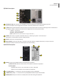
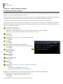
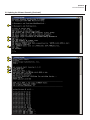
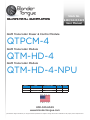
Stock No.
6238/6243/6223
User Manual
QAM Transcoder Power & Control Module
QTPCM-4
QAM Transcoder Module
QTM-HD-4
QAM Transcoder Module
QTM-HD-4-NPU
Status
Date
Document No.
Issue No.
Author
Active
August 17, 2015
651227100B
1
KK
Obsolete
July 7, 2015
651227100A
1
KK
800-523-6049
www.blondertongue.com
©2015 Blonder Tongue Laboratories, Inc. All rights reserved. Specifications are subject to change without notice. Trademarks are the property of their respective owner.
2 QTPCM-4
Instruction Manual
We recommend that you write the following information in the spaces provided below.
Purchase Location Name:
Purchase Location Telephone Number:
QTPCM-4 Serial Number:
The information contained herein is subject to change without notice. Revisions may be
issued to advise of such changes and/or additions.
Correspondence regarding this publication should be addressed directly to:
Blonder Tongue Laboratories, Inc.
One Jake Brown Road
Old Bridge, NJ 08857 USA
Document Number: 651227100B
Printed in the United States of America.
All product names, trade names, or corporate names mentioned in this document are
acknowledged to be the proprietary property of the registered owners.
This product incorporates copyright protection technology that is protected by U.S. patents and other
intellectual property rights. Reverse engineering or disassembly is prohibited.
QTPCM-4 3
Instruction Manual
Table of Contents
SECTION 1 – GENERAL & SAFETY INSTRUCTIONS ........................................................................................................ 4
SECTION 2 – PRODUCT SUMMARY............................................................................................................................... 6
2.1 REVISION HISTORY & REASON................................................................................................................................ 6
2.2 PRODUCT APPLICATION & DESCRIPTION............................................................................................................... 6
2.3 PRODUCT SPECIFICATION........................................................................................................................................ 8
SECTION 3 – INSTALLATION & POWER-UP.................................................................................................................... 9
3.1 UNPACKING .............................................................................................................................................................. 9
3.2 INSTALLATION .......................................................................................................................................................... 9
3.3 POWER-UP................................................................................................................................................................. 9
SECTION 4 – COMMUNICATING WITH THE UNIT........................................................................................................ 10
SECTION 5 – CONFIGURING THE UNIT ........................................................................................................................11
5.1 ACCESSING THE UNIT VIA THE WEB BROWSER................................................................................................... 11
5.2 MAIN > STATUS SCREEN.......................................................................................................................................... 12
5.3 MAIN > INPUT SCREEN............................................................................................................................................ 13
5.4 MAIN > OUTPUT CONFIG........................................................................................................................................ 14
5.5 MAIN > REFRESH TAB.............................................................................................................................................. 16
5.6 NETWORK SCREEN................................................................................................................................................... 16
5.6.1 ADMIN SCREEN..................................................................................................................................................... 18
5.7 TIME SCREEN............................................................................................................................................................ 20
5.8 EVENT LOG SCREEN................................................................................................................................................. 22
5.9 UPDATE SCREEN....................................................................................................................................................... 23
SECTION 6 – REMOTE SOFTWARE UPDATES................................................................................................................ 24
6.1 UPDATING THE SOFTWARE REMOTELY................................................................................................................. 24
4 QTPCM-4
Instruction Manual
Section 1 — General & Safety Instructions
The STOP sign symbol is intended to alert you to the presence of REQUIRED operating and maintenance
(servicing) instructions that if not followed, may result in product failure or destruction.
The YIELD sign symbol is intended to alert you to the presence of RECOMMENDED operating and maintenance
(servicing) instructions.
The LIGHTNING flash symbol is intended to alert you to the presence of uninsulated "dangerous voltage"
within the product's enclosure that may be of sufficient magnitude to constitute a risk of electrical shock.
TO REDUCE THE RISK OF ELECTRICAL SHOCK, DO NOT REMOVE COVER FROM THIS UNIT.
NO USER-SERVICEABLE PARTS INSIDE. REFER SERVICING TO QUALIFIED SERVICE PERSONNEL.
WARNING: TO PREVENT FIRE OR SHOCK HAZARD, DO NOT EXPOSE THIS UNIT TO RAIN OR MOISTURE
NOTE TO CATV SYSTEM INSTALLER
This reminder is provided to call the CATV System Installer’s attention to Article 820-40 of the NEC that provides guidelines for
proper grounding and, in particular, specifies that the cable ground shall be connected to the grounding system of the building, as
close to the point of cable entry as practical.
Safety Instructions
YOU SHOULD ALWAYS FOLLOW THESE INSTRUCTIONS TO HELP ENSURE
AGAINST INJURY TO YOURSELF AND DAMAGE TO YOUR EQUIPMENT.
å
Elevated Operating Ambient - If installed in a closed or multi-unit rack assembly, the operating ambient temperature of the rack environment
may be greater than room ambient. Therefore, consideration should be given to installing the equipment in an environment compatible with the
maximum ambient temperature per Section 2.3.
å
Reduced Air Flow - Installation of the equipment in a rack should be such that the amount of air flow required for safe operation of the equipment
is not compromised.
å
Mechanical Loading - Mounting of the equipment in the rack should be such that a hazardous condition is not achieved due to uneven mechanical loading.
å
Circuit Overloading - Consideration should be given to the connection of the equipment to the supply circuit and the effect that overloading of
the circuits might have on overcurrent protection and supply wiring. Appropriate consideration of equipment nameplate ratings should be used
when addressing this concern.
å
Reliable Earthing - Reliable earthing of rack-mounted equipment should be maintained. Particular attention should be given to supply connections
other than direct connections to the branch circuit (e.g. use of power strips).
å Read all safety and operating instructions before you operate the unit.
å Retain all safety and operating instructions for future reference.
å Heed all warnings on the unit and in the safety and operating instructions.
QTPCM-4 5
Instruction Manual
Safety Instructions - continued
å Follow all installation, operating, and use instructions.
å
Unplug the unit from the AC power outlet before cleaning. Use only a damp cloth for cleaning the exterior of the unit.
å
Do not use accessories or attachments not recommended by Blonder Tongue, as they may cause hazards, and will void the warranty.
å Do not operate the unit in high-humidity areas, or expose it to water or moisture.
å
Do not place the unit on an unstable cart, stand, tripod, bracket, or table. The unit may fall, causing serious personal injury and damage to the
unit. Install the unit only in a mounting rack designed for 19” rack-mounted equipment.
å
Do not block or cover slots and openings in the unit. These are provided for ventilation and protection from overheating. Never place the
unit near or over a radiator or heat register. Do not place the unit in an enclosure such as a cabinet without proper ventilation. Do not mount
equipment in the rack space directly above or below the unit.
å
Operate the unit using only the type of power source indicated on the marking label. Unplug the unit power cord by gripping the plug, not the cord.
å
The unit is equipped with a three-wire ground-type plug. This plug will fit only into a ground-type power outlet. If you are unable to insert the
plug into the outlet, contact an electrician to replace the outlet. Do not defeat the safety purpose of the ground-type plug.
å
Route power supply cords so that they are not likely to be walked on or pinched by items placed upon or against them. Pay particular attention
to cords at plugs, convenience receptacles, and the point where they exit from the unit.
å
Be sure that the outdoor components of the antenna system are grounded in accordance with local, federal, and National Electrical Code (NEC)
requirements. Pay special attention to NEC Sections 810 and 820. See the example shown in the following diagram:
å W
e strongly recommend using an outlet that contains surge suppression or ground fault protection. For added protection during a lightning
storm, or when the unit is left unattended and unused for long periods of time, unplug it from the wall outlet and disconnect the lines between
the unit and the antenna. This will prevent damage caused by lightning or power line surges.
å D
o not locate the antenna near overhead power lines or other electric light or power circuits, or where it can fall into such power lines or circuits.
When installing the antenna, take extreme care to avoid touching such power lines or circuits, as contact with them can be fatal.
å Do not overload wall outlets or extension cords, as this can result in a risk of fire or electrical shock.
å N
ever insert objects of any kind into the unit through openings, as the objects may touch dangerous voltage points or short out parts. This could
cause fire or electrical shock.
å D
o not attempt to service the unit yourself, as opening or removing covers may expose you to dangerous voltage and will void the warranty. Refer
all servicing to authorized service personnel.
å Unplug the unit from the wall outlet and refer servicing to authorized service personnel whenever the following occurs:
o
o
o
o
o
The power supply cord or plug is damaged;
Liquid has been spilled, or objects have fallen into the unit;
The unit has been exposed to rain or water;
The unit has been dropped or the chassis has been damaged;
The unit exhibits a distinct change in performance.
å W
hen replacement parts are required, ensure that the service technician uses replacement parts specified by Blonder Tongue. Unauthorized
substitutions may damage the unit or cause electrical shock or fire, and will void the warranty.
å U
pon completion of any service or repair to the unit, ask the service technician to perform safety checks to ensure that the unit is in proper
operating condition.
Returning Product for Repair (or Credit)
A Return Material Authorization (RMA) Number is required on all products returned to Blonder Tongue, regardless if
the product is being returned for repair or credit. Before returning product, please contact the Blonder Tongue Service
Department at 1-800-523-6049, Ext. 4256 or visit our website: www.blondertongue.com for further information.
6 QTPCM-4
Instruction Manual
Section 2 — Product Summary
2.1 Revision History & Reason
This is the 2nd release of the manual, adding the QTM-HD-4-NPU, updating service features (Section 2.2, below) and
adding note to have all the same input modulation rate on a given QTM-Module (Section 5.3).
2.2 Product Application & Description
Application:
QTPCM-4 (QAM Transcoder Power Control Module) provides control and monitoring of QTM-HD-4 (6243), QTM-HD-4-NPU
(6223) and QTM-HD-Plus (6242) transcoder modules via GUI-based web pages. Local or remote control via the Internet is
accomplished with any computer running a standard web browser. The QTPCM-4 will power up to four (4) QTM-HD-4 (2
slot width) or four (4) QTM-HD-4-NPU (2 slot width); eight (8) QTM-HD-Plus (1 slot width); or a combination of modules
all housed in a QTRC (stk# 6233A) rack chassis. The 3RU chassis, when fully loaded with four (4) QTM-HD-4 or (4) QTMHD-4-NPU and a QTPCM-4, will transcode sixteen (16) QPSK/8PSK satellite transponders to sixteen (16) QAM channels.
The QTM-HD-4 contains (4) independent transcoders in a single module. Each transcoder accepts one (1) input in QPSK or
8PSK format and delivers (1) QAM channel output, therefore each QTM-HD-4 module transcodes (4) satellite transponders
to (4) QAM channels (54-864 MHz). An integrated satellite selector switch allows the operator to select any of the 4 inputs
to any of the transcoders without the need for an external multi-switch.
The QTM-HD-4-NPU functions the same as the QTM-HD-4, but with a “Null Packet” feature that allows adding/removing
null packets to/from the input stream.
The QTM-HD-Plus features a single transcoder, accepting a QPSK or 8PSK input and delivering a single QAM channel output
in the frequency range of 54-864 MHz. This module is typically used in applications requiring QAM 512/1024 modulation.
Servicing Feature
It is recommended to disconnect AC power to the QTPCM-4 when installing or removing QTM modules. When replacing
QTM Modules, simply disconnect the input and output cables along with the power supply/control cabling and remove
the module from the chassis. Install a new “like” module and reconnect the cabling. The QTPCM-4 will automatically
configure the new module with the same settings as the replaced module.
If the QTPCM-4 has to be replaced, remove power and all cabling on the rear of the unit. Replace the module and
reconnect power and cabling. Once the new QTPCM-4 has booted up it will read the configuration settings from the
transcoder modules, store them in memory and return to full system operation, without any further user interface.
QTPCM-4 7
Instruction Manual
QTPCM-4 Description:
1
2
3
5
4
1
CONTROL 10/100: RJ45 connector for 10/100Base-T Ethernet interface for monitoring and configuring the unit.
Only static IP address can be assigned to this interface. The factory default value is 172.16.70.1.
2
IP RESET: When pushed and held for about 6 seconds, the Status LED will flash momentarily indicating the unit has defaulted to
the original IP address, Usernames and Passwords as shipped from the Factory (shown below).
IP address = 172.16.70.1
Username = Admin (case-sensitive)
Password = pass (case-sensitive)
(NOTE: QTPCM-4 must be power cycled for change to take effect.)
3
POWER: LED is Green = AC power is detected. LED is off = indicates (i) AC power is not connected, or
(ii) AC power is connected but the power supply has failed.
4
STATUS: LED is Green = Ready (booted up)
5
INPUT POWER: IEC 14 power inlet plug - rated 105 to 240 VAC; 50/60 Hz; equipped with Slo-blo, 4.0 Amps, 250 V Fuse.
Power/Data: Multi-pin connector for module power and control cabling.
QTM-HD-4 Description:
2
4
3
1
1
STATUS: Provides user feedback based on the following LED conditions:
a) Solid Green ON: Indicates all transcoders in the module are locked to transponders
b) Flash ON/OFF:
1) Output state of one or more transcoders is in OFF or CW Mode.
2) One or more transcoders are not locked to transponders.
2
4-CH QAM OUTPUT: “F” connector for up to four (4) QAM RF outputs 54-864 MHz.
3
L BAND INPUT (1 to 4): “F” connectors for four (4) QPSK/8PSK satellite RF inputs 950-2150 MHz.
4
POWER/DATA: Multi-pin connector for module power and control cabling from QTPCM-4.
8 QTPCM-4
Instruction Manual
2.3 Product Specifications
QTPCM-4 Specifications
General
Alarms/Monitoring/Control
Dimensions (W x D x H)
QTPCM Module: 4.5 x 10.6 x 5.25 inches (114 x 270 x 134 mm)
QTRC Rack Chassis: 19 x 12.0 x 5.25 inches (483 x 305 x 134 mm)
Indicators: Power (Green LED)
Status (Green LED)
Remote Monitoring/Control: GUI-based Menu via web browser
Power: 105 to 240 VAC; 50/60 Hz
Weight: 5.0 lbs (kg)
Operating Temperature: 32 to 122 °F (0 to 50 °C)
Storage Temperature: -13 to 158 °F (-25 to 70 °C)
Operating Humidity: 0 to 95% RH @ 35 °C max, non-condensing
Storage Humidity: 0 to 95% RH @ 35 °C max, non-condensing
QTM-HD-4 Specifications
Input
Output
Connector: 4x “F” Female
Standards: QPSK & 8PSK (DVB-S, DVB-S2, DCII, LDPC/BCH, & Turbo FEC)
Symbol rate
DVB-S: Variable; 1 to 45 MSymbols/sec (Mbaud)
DVB-S2: Variable; 5 to 33 MSymbols/sec (Mbaud)
8PSK Turbo: Variable; 2 to 30 MSymbols/sec (Mbaud)
Frequency Range: 950 to 2150 MHz
Frequency Granularity: 1 MHz
Bandwidth: Variable, up to 36 MHz
Capture Range: ± 5 MHz
Code Rate
DVB-S:
DVB-S2 (QPSK):
DVB-S2 (8PSK):
Turbo FEC (QPSK):
Turbo FEC (8PSK):
Auto Detect; 1/2, 2/3, 3/4, 5/6, 7/8, DC II
Auto Detect; 1/2, 3/5, 2/3, 3/4, 4/5, 5/6, 8/9, 9/10
Auto Detect; 3/5, 2/3, 3/4, 5/6, 8/9, 9/10
Auto Detect; 1/2, 2/3, 3/4, 5/6, 7/8
Auto Detect; 2/3, 3/4, 5/6, 8/9
Forward Error Correction DVB / DigiCiper® II
(FEC):
Connector:
Modulation:
Standard:
DVB Symbol Rate:
Frequency Range:
Tuning:
Channels’ Bandwidth:
RF Level:
RF Level Adjustment Range:
Frequency Tolerance:
Frequency Stability:
Amplitude Flatness:
Phase Noise:
Spurious:
Broadband Noise:
Impedance:
Carrier Suppression:
Return Loss:
Signal-to-Noise Ratio (SNR):
MER:
I/Q Phase Error:
I/Q Amplitude Imbalance:
1x “F” Female (4x RF QAM channels combined)
QAM 16, 32, 64, 128, and 256
ITU-T J.83; Annex A and B
Variable; up to 7 MSymbol/sec (MBaud)
54 to 864 MHz
CATV Channel Selectable (CH. 2 to 135)
4x 6 MHz in any 42 MHz-wide spectrum
+40 dBmV ±1 dB (100 dBμV ±1 dB)
+32 to +42 dBmV, 1 dB increment
± 0.5 kHz @ 77°F (25° C)
± 5 kHz over 32° to 122° F (0 to 50° C)
± 0.25 dB (over 6 MHz channel)
-95 dBc (@ 10 kHz)
-60 dBc
-70 dBc (@ +40 dBmV output level, 5.5 MHz bandwidth)
75 Ω
45 dB
14 dB typical
Greater than 40 dB typical
Greater than 39 dB typical
Less than 1 degree
Less than 1%
Input Level: -65 to -20 dBm
Impedance: 75 Ω
Return Loss: Greater than 9 dB
Alarms/Monitoring/Control
Indicators
QTM-HD-4 Module: Status (Green LED)
General
Dimensions (W x D x H)
QTM-HD-4 Module: 3.0 x 10.6 x 5.25 inches (38 x 270 x 134
mm)
Power Dissipation
QTM-HD-4 Module: 21 W
Weight
QTM-HD-4 Module: 1.7 lbs (0.77 kg)
Operating Temperature: 32 to 122 °F (0 to 50 °C)
Storage Temperature: -13 to 158 °F (-25 to 70 °C)
Operating Humidity: 0 to 95% RH @ 35 °C max, non-condensing
Storage Humidity: 0 to 95% RH @ 35 °C max, non-condensing
QTPCM-4 9
Instruction Manual
Section 3 – Installation & Power-up
3.1 Unpacking
You will find the following items in the box:
• QTPCM-4 (QTY=1)
• Power Cord with IEC C13 line socket and 3-pin Type b NEMA 5 plug (QTY=1)
• A hardware bag (item 741018800) containing the following:
Cable wire bracket (QTY=1)
• DC/Control cable harness (QTY=2)
3.2 Installation
The QTPCM-4 AND QTM-HD-4s are designed to be installed in a QTRC chassis (shown below) and a standard 19-inch
(483 mm) rack (EIA 310-D, IEC 60297, and DIN 41494 SC48D).
FOR SAFE AND RELIABLE OPERATION, THE GROUND PIN OF THE POWER CORD PLUG
MUST BE GROUNDED PROPERLY.
3.3 Power-up
Connect the Power/Data cables 1- 4 from the QTPCM-4 to the QTM-HD-4 modules. Connect the QTPCM-4 line cord to a
117 VAC, 60 Hz outlet. The “POWER” LED on the front-panel will light green. After approximately 30 seconds, the "Status"
LED will light green, indicating the unit has booted and is ready for operation.
STATUS LED's of QTM modules are on steady (green) except for OFF/CW or NOT LOCKED.
IT IS RECOMMENDED TO DISCONNECT AC POWER TO THE QTPCM-4 PRIOR TO
INSTALLING OR REMOVING ANY QTM-4 MODULES.
10 QTPCM-4
Instruction Manual
Section 4 – Communicating with the Unit
Local or remote communication with the unit is only possible through a GUI-based menu via any standard web browser.
Before you can communicate with the unit, you must configure your computer’s IP address to be in the same subnet as the
units default IP address. To do so, follow these steps:
(1) Plug one end of the Ethernet cross cable that is provided in the hardware bag to unit’s rear-panel RJ45 interface marked
“Control 10/100”. Plug the other end of the cable to your computer.
(2) The factory default IP address of the unit is 172.16.70.1. To be able to communicate with the unit, you must first change
your computer's IP address.
The following steps explain how to do this for a computer with Windows XP operating software:
(a) On your computer, open the "Control Panel"
(b) Double-click on "Network Connections"
(c) Right-click on the "Local Area Connection", and then click on the "properties".
(d) A dialog box entitled "Local Area Connection Properties" will appear. In this box, double-click on the "Internet Protocol
(TCP/IP)".
(e) A dialog box entitled "Internet Protocol (TCP/IP) Properties" will appear. Select the "Use the following IP address"
option and enter the following addresses:
IP address: 172.16.70.2
Subnet mask: 255.255.255.0
No need to enter a value for the Default Gateway.
Click OK to close the dialog box. Now your computer is ready to communicate with the unit.
-OR The following steps explain how to do this for a computer with Windows 7 operating software:
(a) On your computer, open the "Control Panel"
(b) Click on “Network and Internet”
(c) Click on the "View network status and tasks"
(d) Click on “Change Adapter Settings” on left hand side of the window
(e) Right-click on the "Local Area Connection", and then click on the "properties".
(f) A
dialog box entitled "Local Area Connection Properties" will appear. In this box, double-click on the "Internet Protocol
Version 4 (TCP/IPv4)".
(g) A
dialog box entitled "Internet Protocol Version 4 (TCP/IPv4) Properties" will appear. Select the "Use the following IP
address" option and enter the following addresses:
IP address: 172.16.70.2
Subnet mask: 255.255.255.0
No need to enter a value for the Default Gateway.
Click OK to close the dialog box. Now your computer is ready to communicate with the unit.
QTPCM-4 11
Instruction Manual
Section 5 - Configuring the Unit
5.1 Accessing the Unit Via the Web Browser
You must complete the steps described in Section 4 before proceeding as follows:
1. Open a web browser on your computer (Internet Explorer 7 or higher is recommended) and enter the following URL
address (http://172.16.70.1). The "Login" Screen (Figure 5.1) will appear.
Figure 5.1 - "Login" Screen
2. Enter the following case-sensitive factory-default Username and Password, and click on the "Submit" button.
NOTE: When logged in as Admin, the user has read and write permission. Only one Admin can be logged in
at a time. When logged in as Guest, the user has only read permission. Up to four Guests can be logged in
simultaneously.
Username = Admin (case-sensitive)
Password = pass (case-sensitive)
- OR Username = Guest (case-sensitive)
Password = pass (case-sensitive)
Monitoring and configuration of the unit is achieved via a series of web pages described in following sections. The following
read-only information is displayed in a blue “page header”on top of each web page:
ESN: unit’s Serial number
Headend name: a user-defined field to make identification easier
Temperature: temperature of unit’s chipset
Uptime: time elapsed since last time the unit was turned on
Location: a user-defined field to make identification easier
As shown in Figure 5.2, under the blue “page header” the following Primary tabs will appear:
• Primary tab “Main” includes the following sub-tabs: Status, Input Config, Output Config, and Refresh.
• Primary tab “Network” doesn’t include any sub-tab.
• Primary tab “Time” doesn’t include any sub-tab.
• Primary tab “Event Log” doesn’t include any sub-tab.
• Primary tab “Logout” doesn’t include any sub-tab.
• Primary tab “Update” doesn’t include any sub-tab.
Each Primary and sub-tab is described in the subsequent Sections.
12 QTPCM-4
Instruction Manual
5.2 "Main > Status" Screen
The “Main > Status” screen (Figure 5.2) is a “read only” screen and displays Input, and Output information
of the transcoder modules. The screen is automatically refreshed every 30 seconds.
1
2
3
4
5
6
7
8
Figure 5.2 - "Main > Status" Screen
In the section entitled “Input” under the green header, the following parameters about each input program in the TS are
displayed:
1
Input: The first number indicates the module number and the second number indicates the L-Band input (satellite
1 to 4) selected for it.
2
Frequency: L Band center frequency of the transponder
3
Modulation: indicates the modulation type of the input program.
4
Input Status: SNR of the transponder. The cell will be green when locked and red when not locked to the transponder.
5
Input Baud Rate: Baud rate of the transponder being received.
In the section entitled “QAM Output” under the dark blue header, the following parameters about each output is displayed:
6
QTM Module: Main transcoder module number (1-4) with transcoder designator (a-d)
7
Channel: QAM RF output channel
8
Output State:
NORMAL = normal QAM RF channel (GREEN Highlight)
OFF = QAM RF channel turned off (RED Highlight)
CW = CW is a calibrated reference signal that replaces the Normal QAM output. It is used for measuring and
setting the RF output signal level when only analog test instruments are available. Activating the CW mode on any
transcoder (a-d) will affect all others (RED).
QTPCM-4 13
Instruction Manual
5.3 "Main > Input Config" Screen
The “Main > Input Config” screen (Figure 5.3a) is a “user-configurable” screen where the L-Band center frequencies, input
source (satellite) and modulation tuning mode parameters can be configured. The QAM output section (blue header) is
displayed as a read-only.
1
2
3
Figure 5.3a - "Main > Input Config" Screen
1
Frequency: Enter the desired L Band center frequency of the transponder in MHz.
2
L-BAND Input: Select the desired satellite input for the transponder being tuned.
3
AUTO:
Auto: Auto box is checked (recommended setting). Unit searches for
the correct Input Modulation format of the transponder to lock on to.
Manual: Auto box is not checked. User must select the proper Input
Modulation (Figure 5.3b) and enter in the baud rate of the transponder.
Figure 5.3b - Manual Mode
If not properly configured, the STATUS indicator on the transcoder module will continuously
blink indicating the transcoder is not locked.
The mode selected (Auto/Manual) on the "Input Config" screen will also be applied to the
"Output Config" screen and vice versa.
Do not mix different input modulation rates within the same QTM-HD unit. The modulation rate needs to be
either ALL 8PSK or ALL QPSK in the same unit.
Remember to click on the SAVE button to apply the new values/configurations.
14 QTPCM-4
Instruction Manual
5.4 "Main > Output Config" Screen
The “Main > Output Config” screen (Figure 5.4a) is a “user-configurable” screen where the output RF QAM channels, levels
and status are set. The Input section (green header) is displayed as a read-only.
1
2
3
4
5
6
Figure 5.4a - "Main > Output Config" Screen
1
Auto: Auto mode (recommended setting) searches for the correct output settings to match the input source. When
not in Auto mode (check box unmarked), the user must manually select the proper QAM mode and baud rate for the
input source from a series of drop-down boxes.
Note: If not properly configured the module will not provide the proper output.
2
QAM Mode: This is a read-only field when in Auto Mode. When in Manual mode, the drop down selections are: 64B,
256B, 16A, 32A, 64A, 128A or 256A.
3
QAM Baud Rate: This is a read-only field when in Auto Mode. When in Manual mode, user must enter the QAM
Baud Rate in Mbd/S.
QTPCM-4 15
Instruction Manual
5.4 "Main > Output Config" Screen (Continued)
1
2
3
4
5
6
Figure 5.4b - "Main > Output Config" - Selected Channel/Frequencies
4
Channel (STD): Select the beginning desired Channel/Frequency on the first transcoder from its pull down menu.
The remaining 3 transcoder sections on each module will display only channels within a 42 MHz bandwidth starting
with the first channel selected. Channel/Frequencies that have already been selected are highlighted in RED to avoid
duplications (Figure 5.4b). Channel/Frequency selections should be in increasing (higher) order from the first (top) to
the last (bottom) transcoder within each module and from module 1 to 4.
5
RF Level dBmV: Pull down level selection. Range is 32 to 42 dBmV in 1 dB increments.
6
Output State: There are 3 available settings, Normal, Off and CW.
NORMAL = QAM modulated output is present. Changing any output to Normal mode changes all outputs of the
same QTM-HD-4 module to normal mode.
OFF = Output is turned off. (No RF output present) Outputs for each channel can be turned on and off independently.
CW = Continue Wave (tone) is on, replacing the normal QAM output with a calibrated RF un-modulated signal. CW
mode facilitates user level measurements when only analog test instruments are available. Changing any output
to CW mode changes all outputs on the same QTM-HD-4 module to CW mode.
Remember to click on the SAVE button to apply the new values/configurations.
16 QTPCM-4
Instruction Manual
5.5 "Main > Refresh" Tab
The “Main > Refresh” tab can be clicked while you are on any of the following sub-tab screens: “Status”, “Input Config”,
and “Output Config”. When clicked, it will update all relevant fields/parameters of the active screen as that
information is retrieved from the QTPCM-4 in a real-time basis.
5.6 "Network" Screen Tab
The “Network” screen (Figure 5.6) is a user-configurable screen where the following parameters are configured or displayed:
1
2
3
4
5
6
7
8
9
10
11
12
13
14
15
16
17
18
19
20
Figure 5.6 - "Network" Screen
QTPCM-4 17
Instruction Manual
5.6 "Network" Screen Tab (Continued)
1
Ethernet 1: indicates the MAC Address of the "10/100 Control" Port
2
Software Version: indicates the software version of the QTPCM-4.
3
FPGA1 Version: Displays the current firmware version.
4
QTM Version (Module No. 1): indicates the current firmware version of Module 1
5
QTM Version (Module No. 2): indicates the current firmware version of Module 2
6
QTM Version (Module No. 3): indicates the current firmware version of Module 3
7
QTM Version (Module No. 4): indicates the current firmware version of Module 4
8
QTM Version (Module No. 5): indicates the current firmware version of Module 5
9
QTM Version (Module No. 6): indicates the current firmware version of Module 6
10 QTM Version (Module No. 7): indicates the current firmware version of Module 7
11 QTM Version (Module No. 8): indicates the current firmware version of Module 8
12 Serial Number: indicates the unit's serial number
13 Headend Name: a user-defined field to make identification easier
14 Location: a user-defined field to make identification easier
15 Login Timeout (Minutes): indicates the period of time before the unit logs itself out if there is no activity on the web
screens. Range is 5, 15, 30, or 60 minutes.
16 IP Address: Read-Only field. See section 5.6.1 for details
17 Subnet Mask: Read-Only field. See section 5.6.1 for details
18 Default Gateway: Read-Only field. See section 5.6.1 for details
19 Event Log Destination: Read-Only field. See section 5.6.1 for details
20 Event Log Destination Port #: Read-Only field. See section 5.6.1 for details
18 QTPCM-4
Instruction Manual
5.6.1 "Admin.html" Hidden Screen
This screen allows the user to change/modify the IP network parameters, as well as the Username and Password values
for the unit, user must be logged in to the unit as “Admin” to access the hidden screen shown in Figure 5.6.1. The
"Admin" screen is accessed by typing the URL of the unit followed by a forward slash and Admin.html, for example:
http://172.16.70.1/Admin.html.
1
2
3
4
5
6
7
8
9
10
11
12
13
14
15
16
17
18
Figure 5.6.1 - "Admin" Screen
QTPCM-4 19
Instruction Manual
5.6.1 "Admin.html" Hidden Screen (Continued)
The following parameters can be modified:
1
Login: is the Administrator’s login (10 characters maximum). This login allows the user to make changes to any area of the
unit. The factory default Login is “Admin”. Login is case sensitive.
2
Current Password: is the Administrator’s Current Password (10 characters maximum). The factory default password is
“pass”. Password is case sensitive and will not be displayed.
3
New Password: used only if the user wants to change the current Administrator’s password. User must enter a new
password (10 characters maximum). Password is case sensitive and will not be displayed.
4
Confirm New Password: User must enter the same password as entered in 3 above. If the password entered in 3 & 4
does not match, an error message will be displayed.
5
Guest Login: is the Guest login (10 characters maximum). This login allows the user to view the unit settings but does not
allow any changes. The factory default Guest Login is “Guest”. Login is case sensitive.
6
Current Guest Password: is the Current Guest Password (10 characters maximum). The factory default Guest password is
“pass”. Password is case sensitive and will not be displayed.
7
New Guest Password: used only if the user wants to change the current Guest password. User must enter a new password
(10 characters maximum). Password is case sensitive and will not be displayed.
8
Confirm Guest Password: User must enter the same password as entered in 7 above. If the password entered in 7 & 8
does not match, an error message will be displayed.
9
System Watchdog: When Enabled, automatically reboots the unit if the Operating System stops working. When Disabled, a
manual reboot would be required in such case.
10 IP Address: is the static IP address that is assigned to the unit. It allows the user to access the unit via the web interface.
The factory default IP address is 172.16.70.1.
11 Subnet Mask: is the Subnet Mask address of the unit. It allows the user to access the unit from another network via the
web interface. The factory default Subnet Mask is 255.255.255.0.
12 Default Gateway: is the gateway address of unit. It allows the user to access the unit from another network via the web
interface. The factory default Subnet Mask is 172.16.70.254. 13 Event Log Destination: is the IP address of the remote server, to which Syslog sends the activities recorded by QTPCM-4 for
monitoring and troubleshooting purposes.
14 Log Destination Port #: is the Error Log Destination port to which a duplicate of the error messages created by the unit can
be forwarded for monitoring and troubleshooting purposes. The factory default value, which cannot be modified, is 514.
15 Time Server IP: is the IP address for the Time Server from where the unit can obtain its clock reference (see Section 5.7 for
details).
16 Syslog Errors: is to enable/disable QTPCM-4 to forward error messages (in red font) to syslog.
The factory default value is disabled.
17 Syslog Informational: is to enable/disable QTPCM-4 to forward information messages (in blue font) to syslog.
The factory default value is disabled.
18 Syslog Feedback: is to enable/disable QTPCM-4 to forward feedback or confirmation messages (in green font) to syslog.
The factory default value is disabled.
Remember to click on the SAVE button to apply the new values/configurations.
20 QTPCM-4
Instruction Manual
5.7 "Time" Screen
The "Time" screen (Figures 5.7a and 5.7b) allows the user to set the current date and time for the QTPCM-4. It is
recommended to use the "automatic" option which allows the unit to automatically acquire time settings from a "Time
Server", in which the user must enter the IP address of the time server (see Section 5.6.1 for details). The time server
specified must support the Network Time Protocol (NTP) in order for automatic time acquisition to work properly.
1
2
3
4
6
Figure 5.7a - "Time" Screen (Manual)
5
6
Figure 5.7b - "Time" Screen (Automatic)
QTPCM-4 21
Instruction Manual
5.7 "Time" Screen (Continued)
1
Current Date (MM/DD/YYYY): Date can be set with drop-down selections. (Manual Configuration Mode)
2
Current Time (24hr): Time can be entered in 24 hour format: hour/minutes/seconds. (Manual Configuration Mode)
3
Configuration Method: Selects either Manual or Automatic Time Zone Settings.
4
Automatically Adjust for Daylight Savings Time: The user can apply the Daylight Savings (DST) automatically by
selecting "yes". Selecting "No" does not provide any time changes from information entered under 6 .
5
Time Zone: The local time zone on Coordinated Universal Time (UTC) can be set. Refer to Figure 5.7b. (Automatic
Configuration Mode)
6
DST Settings: User selectable start and stop dates and times for Daylight Savings Time. When "Automatically Adjust
for Daylight Savings Time" is set to "Yes", the time will be changed accordingly.
Remember to click on the SAVE button to apply the new values/configurations.
22 QTPCM-4
Instruction Manual
5.8 "Event Log" Screen
The “Event Log” screen (Figure 5.8) is a “read and write” screen where the following parameters can be displayed or
configured. The data in Event Log can be forwarded to an event log database through the Admin hidden configuration
screen. (Section 5.6.1 for details)
1
2
3
4
5
6
Figure 5.8 - "Event Log" Screen
The displayed lines are color coded as follows:
Red font = error message
Blue font = informational message
Green font = confirmation or feedback message
1
Event Log Destination: see 13 of Section 5.6.1 for details.
2
Event Log Destination Port #: see 14 of Section 5.6.1 for details.
3
SNMP Destination Port #: Optional for future release
4
Clear Log: allows the user to clear the records generated during unit’s boot-up process and operation afterward. The
records are cleared if the unit loses power.
5
Lines to Display: allows the user to select the number of lines to be displayed. The unit supports up to 400 MB of data
or approximately 65,000 lines. The range is 1 to 65,535.
6
Save Number of Displayed Lines: Saves changes made to 5 "Lines to Display". Please note that this setting only
affects the amount of lines shown on display and does not save to any file or database.
QTPCM-4 23
Instruction Manual
5.9 "Update" Screen
The update screen permits the user to easily apply firmware updates to QTM-HD-4 modules.
Note: This feature is only applicable for updating QTM-HD-4 modules. For information regarding QTM-HD and QTM-HD Plus
firmware updates please contact the factory.
Figure 5.9 - "Update" Screen
The update information for each QTM-HD-4 unit resides within the QTPCM-4 module. Important: Prior to pressing the
UPDATE button, be sure the QTPCM-4 module has the latest firmware release. This can be done by visiting our website or
contacting our Technical Support Department. The website product firmware information can either be found under the Main
Page - Support Tab or by going to the QTPCM-4 product page document tab. Information regarding updating the QTPCM-4
firmware is in Section 6.0, “Updating the Software Remotely” of this manual.
Detailed description of QTM-HD-4 Module Update:
1. The update process with take approximately 7 minutes per module if the FPGA code does not require updating. With FPGA
upgrade, time is approximately 20 minutes per module. Update page will indicate the appropriate time.
2. Updates are applied sequentially starting with Module 1.
3. during the update the modules will continue to transcode the input signals.
4. At the end of a module update, a soft reset is applied and the QAM output will be off for approximately one minute.
5. When all modules have been updated, the QTPCM-4 will update the webpages accordingly and document the activity in
the "Event Log".
6. If the QTPCM-4 is unable to re-establish communication with one or more modules within 2 minutes, a hard-reset will be
applied to those modules.
7. During the hard-reset, the QAM Output of the modules will be off for approximately one minute.
8. Application of the hard-reset will be documented in the "Event Log".
24 QTPCM-4
Instruction Manual
Section 6 — Remote Software Updates
6.1 Updating the Software Remotely
The QTPCM-4 requires 1 PROM to be updated for new revision changes. As referenced in Section 5.9 Update Screen, the QTPCM-4
firmware also contains the QTM-HD-4 updates. Once the QTPCM-4 has been updated following the procedure below, the QTM-HD-4
modules it serves can be updated as shown in Section 5.9.
To obtain the latest firmware revision, please visit our website or contact our Technical Support Department. The website product firmware
information can be found under the Main Page - Support Tab or by going to the QTPCM-4 product page document tab.
Note: It is recommended to copy the EPCS_1_ver#.bin file to the root directory of your computer. ie, My Computer >C:
The updating procedure uses the Command Prompt application on your computer. For Windows, it can be found under Programs >
Accessories > Command Prompt. All commands are case sensitive and file names must be entered exactly. The Command Prompt must
be in the same folder as the EPCS file.
1
From the Command Prompt
Type: ftp -A 172.16.70.1
NOTE: there is a space between “ftp” and “–A” there is also a space between “–A” and the IP address
(The example assumes the default IP address. Use current IP address of the unit)
2
Type: bin
Press ENTER
3
Type: put EPCS_1_ver#.bin (NOTE: Use exact file name)
Press ENTER
4
Type: bye
Press ENTER
5
Telnet into the unit from the Command Prompt
Type: telnet 172.16.70.1 (NOTE: Assumes default IP)
Press ENTER
6
Log into the unit.
Username: Admin
Press ENTER
7
Password: pass
Press ENTER
8
Type: cd home/ftp
Press ENTER
9
Type: ls
Press ENTER
5
10 Type: epcs –e1 EPCS_1_ver#.bin (NOTE: Use exact file name)
Press ENTER
a. Note there is a space between “epcs” and “–e1”
b. Note there is a space between “–e1” and the file name
The QTPCM-4 must be rebooted once the update has finished being applied to complete the update process.
To automatically reboot the unit use telnet and enter the following:
Type: epcs –c (NOTE: Space between “epcs” and “–c”)
Press ENTER
Powering off then on with the line cord IEC connector can also be done.
QTPCM-4 25
Instruction Manual
6.1 Updating the Software Remotely (Continued)
1
2
3
4
6
7
8
9
10
26 QTPCM-4
Instruction Manual
NOTES:
Extended Warranty Program
STANDARD TERMS & CONDITIONS OF THE EXTENDED WARRANTY
A.
THE EXTENDED WARRANTY AGREEMENT (EWA)
If during the period following the expiration of the Blonder Tongue Manufacturers’ Standard Warranty ( Copy Included) the products which constitute the subject
matter of the extended warranty, manifest any manufacturing or similar such defects then Blonder Tongue shall at its option repair or replace the product. It is
emphasized that the extended warranty is in effect an extension of the Blonder Tongue Warranty and covers the items stipulated in Paragraph B to the exclusion of
the terms in Paragraph C of this agreement. Eligibility to purchase EW is limited to 90 days following initial shipment on selected products of sufficient value.
The product/products included in this extended warranty agreement are listed in the invoice that accompanies the EWA. Term of the extension will be ______
year(s). Purchase Order is required for extended warranty coverage.
B.
WHAT IS COVERED?
1.
If a product has been determined to have failed, which falls within the Terms & Conditions of this EWA, Blonder Tongue Inc. may at its sole discretion
repair, modify or replace its component parts that are defective at 100% coverage for parts and labor.
2.
A loaner unit may be available on request; PO required.
3.
Product is manufactured by Blonder Tongue.
4.
Extended warranty period is up to and not to exceed 24 months and sold in increments of 12 months. Order # 9981 for 1 year and #9982 for 2 year
extensions.
5.
Return of repair or replaced product shipping costs for ground shipments.
6.
Firmware upgrades at no charge with automatic notification.
C.
WHAT IS NOT COVERED?
1.
The warranty does not cover any defects caused by foreign objects /connection errors .
2.
Use other than by the customer at the declared address appearing in this document.
3.
Failure by the end user to comply with the manufacturers’ instructions for installation, maintenance or use.
4.
The use of accessories which have not been approved by Blonder Tongue.
5.
The application and/or use of any incorrect or abnormal electrical supply to the product.
6.
Any defect in wiring or electrical connections which does not form part of the product at the time of the original purchase.
7.
Neglect, misuse, or willful abuse of the product.
8.
Any repairs or attempted repairs of the product by any person other than Blonder Tongue Service Department.
9.
Any modification of the product by any person other than Blonder Tongue Service Department.
10. Fire, flood, war, civil disturbance, industrial action, acts of God or any other causes beyond the reasonable control of Blonder Tongue.
11. Any defect caused by lightning strike or power surges.
12. Shipping costs to return products to Blonder Tongue for warranty service.
13. Blonder Tongue will not in any circumstances be liable for any consequential loss or damages suffered by the customer whether directly or in directly
related defect in the product to the extent permissible by law.
14. Repairs may not be effected without prior authorization from Blonder Tongue Laboratories.
D.
GENERAL
1.
The customer shall notify Blonder Tongue Laboratories in writing within ten days of any change of his or her address.
2.
Customer must provide original purchase receipt and serial number to initiate extended warranty coverage.
3.
The fee paid for the warranty is not refundable under any circumstances unless cancelled within seven days of purchase.
4.
The customer shall take all reasonable precautions to maintain the product is maintained in good working order.
5.
The warranty contract ceases to exist if the product is replaced or a credit is given to the customer. Any monies paid for the warranty contract are forfeited
and not refundable. This is only applicable when the product is out of the manufacturer’s warranty.
6.
The extended warranty period as stated on the Extended Warranty Agreement shall be the governing period notwithstanding any additional supplier
warranty on specific components.
7.
The warranty shall in no way effect the terms and conditions of the sale agreement in terms of which the customer bought the product.
8.
The extended warranty is limited to the terms and conditions herein contained
9.
No agreement, varying, adding to, amended, deleting, or cancelling this warranty shall be effective unless given in writing (email is acceptable) and signed
by or on behalf of both parties.
10. The cost of the extended warranty is 8% of the purchase price for a 1 or 2 year extension beyond the Blonder Tongue standard warranty. e.g. A product
st
price of $1000 will be $80 for the 1 year (12 mos) and additional $80 for 2 year (24 mos) extension for a total of $160.
11. Warranty product return postage paid to: Blonder Tongue Laboratories, Inc.
Attn: Warranty Service Dept.
1 Jake Brown Road
Old Bridge, NJ 08857
Contact Blonder Tongue at 800-523-6049 ext. 555 to order extended warranty service.
Blonder Tongue Laboratories, Inc.
Limited
Warranty
Limited Warranty
Blonder Tongue Laboratories, Inc. (BT) will at its sole option, either repair or replace (with a new or factory reconditioned product,
Seller will at its sole option, either repair or replace (with a new or factory reconditioned product, as Seller may determin e) any product manufactured or sold (or in
ascase
BT ofmay
determine)
any
product
manufactured
by BT
which
proves
totobemeet
defective
in factory
materials
or that
workmanship
orthe
fails
toof
Blonder
Tongue
Laboratories,
Inc.
(BT) iswill
at its in
sole
option,
repair
ororreplace
(with
a applicable
new or
reconditioned
as
BT
may
the
software,
licensed) by
Seller
which
defective
materials
oreither
workmanship
fails
the
specifications
are product,
in effect on
date
meet the
specifications
whichas are
on
theto
date
of shipment
orfor
such
other
specifications
asthemay
have
been
expressly
shipment
or such
other specifications
may
have
been expressly
agreed
upon
in writing:
(i)
aorperiod
of three
(3)
date
of original
purchase
determine)
any
product
manufactured
by in
BTeffect
which
proves
be defective
in materials
workmanship
oryears
fails from
to meet
the specifications
whichforareall
stock
hardware
than
specifically
referenced
herein
aof
shorter
warranty
period);
(ii)
for
a (i)
period
one
(1)ofyear
the
agreed
upon
in writing
(i)
fororthose
asuch
period
one
(1) year
thehaving
dateexpressly
original
purchase
such
shorter
period
of from
time
asdate
may
in
effect
on
theproducts
date
of (other
shipment
otherofspecifications
as from
maybelow
have
been
agreed
upon
in(or
writing
for aofperiod
one
(1) year
fromof
original
purchase,
with
respect
to agreement
all MegaPort™,specific
IPTV products,
test
equipmentsoftware
and fiber optics
receivers,
transmitters,
couplersto
and
integrated receiver/distribution
be
set
forth
in
the
license
to
the
particular
being
licensed),
with
respect
iCentral™
(hardware
and
the
date
of
original
purchase
(or
such
shorter
period
of
time
as
may
be
set
forth
in
the
license
agreement
specific
to
the
particular
software
being
amplifiers; (iii) for a period of one (1) year from the date of original purchase (or such shorter period of time as may be s et forth in the license agreement specific to
software)
and
all other
software
products
(including
software)
licensed
from
BT,embedded
(ii))Core
forProduct
asoftware)
period
of one
(1)
year
from
licensed),
with
respect
to iCentral™
(hardware
and
software)
and
all other
software
products
(including
licensed
from
BT,
(ii) )
the
particular
software
being
licensed
from
Seller) with
respect
to allembedded
software
products
licensed
from Seller
(other
than
Software)
that
is (a)
developed
the
date
purchase,
respect
all does
MegaPort,
IPTV
and
fiber
optics
receivers,
couplers
and
for
aaspecific
function
or application,
(b)with
complimentary
topurchase,
and
not
function
without
the Core
Product
Software,
and
(c) listed
with
a specific
model
number
and
for
periodof
oforiginal
one (1)
year
from the
date of
originalto
with
respect
toproducts
all MegaPort™,
IPTV
products,
and
fibertransmitters,
optics
receivers,
transmitters,
stock
number in
Seller’s Price List (“Non-Core
Software”);
(iv) for a TRAILBLAZER™,
period of ninety (90) RETRO-LINX™
days from the dateand
of original
purchase,
with
respect to
-serialized
integrated
receivers/distribution
amplifiers
(including
TWIN
STAR™
products)
asasnon
well
as
for
couplers
and
integrated
receiver/distribution
amplifiers
(including
TRAILBLAZER™,
RETRO-LINX™
and
TWIN
STAR™
products)
well
as
for
products
and accessories,
such as parts, satellite
sub-assemblies,
splitters
and all other
soldthree
by Seller
(other
than
Corethe
Product
Software
and Refurbished/Closeout
VideoCipher®
& DigiCipher®
receivers,
and
for
aproducts
period
years
from
date
of original
purchase,
with
DigiCipher
satellite
receivers,
(iii)(i)for
a period
three(iii)
(3)warranty
years
from
theof
date
of (3)
original
purchase,
with
respect
to allincluded
other
BT
Products)
not ®
otherwise
referred
to inand
clauses
through
(iii) of
above.
The
period
for
computer
programs
in machine-readable
form
in aproducts.
hardware
respect
to
all
other
BT
products.
Notwithstanding
the
foregoing,
in
some
cases,
the
warranty
on
certain
proprietary
sub-assembly
product,
which are essential
for the in
functionality
thereof
as specifically
stated in
the published
product specifications
(“Core Productby
Software”)
willvendors
be coincident
Notwithstanding
the foregoing,
some cases,
the warranty
on certain
proprietary
sub-assembly
modules manufactured
third-party
and
modules
manufactured
by
third
party
vendors
contained
in BTProduct
products
andis on
private-label
products
manufactured
with
the warranty
of the
applicable
hardware
product and
within
which
such Core
Software
installed.
contained
in
BTperiod
products
and
on
certain
private–label
products
manufactured
by third-parties
forcertain
resale by
BT are of shorter
duration
or otherwise
by third
parties
for standard
resale by BTlimited
are ofwarranty.
shorter In
duration
or otherwise
more
than
the
standardproprietary
BT limited
warranty. modules
In such
more
limited
than
such the
cases,
BT'swarranty
warranty
withlimited
respect
to Product
such
third-party
sub-assembly
Software
patches,
bugthe
fixes, updatesBT
or workarounds
do not extend
original
period
of
any Core
Software or
Non-Core Software.
cases,
BT’s
warranty
with
respect
to
such
third
party
proprietary
sub-assembly
modules
and
private-label
products
will
be
and private-label products will be limited to the duration and other terms of such third-party vendor's warranty. In addition, certain products,limited
that are
to the duration
and herein
other
of such third party vendor’s warranty. In addition, certain products, that are not manufactured
Notwithstanding
anything
toterms
the
not manufactured
but are
resold
by contrary,
BT, carry the original OEM warranty for such products. The limited warranty set forth in this paragraph does not
but are resold by BT, carry the original OEM warranty for that product. The limited warranty set forth in this paragraph does not
apply
to any
product
sold
bysoftware
BT, which
at
the properly
time of sale
constituted
a Refurbished/Closeout
(i)
Seller’s
obligation
for
thatwhich
when
installed
and used
does not a
substantially
conform
to the publish ed specifications in effect when the
apply
tosole
any
product
sold
by BT,
at the time
of sale
constituted
CloseoutProduct.
Product.
software is first shipped by Seller, is to use commercially reasonable efforts to correct any reproducible material non-conformity (as determined by Seller in its sole
discretion)
by providing
the
customer
with:
(a) telephone
or e-mail
access
to
non-conformance so
that Seller
can may
verifydetermine)
reproducibility,
a software
patch
(b)
BT will
its sole
option,
either
repair
or replace
replace
(with
orreport
factory-reconditioned
product,
as BT
any (b)
product
sold
by BTor
BTfix,
will
itsatsole
either
repair
or
(witha and
anew
new
or
factory
reconditioned
asdefective
BT mayexternal
determine)
any
product
bug
if at
available
or aoption,
workaround
to bypass
the
issue if available,
(c) where
applicable,
replacement orproduct,
damaged or
media, such
as
CD-ROM
which
at
the
time
of
sale
constituted
a
refurbished
or
closeout
item
(“Refurbished/Closeout
Product”),
which
proves
to
be
defective
in
materials
or
soldonby
BT the
which
at the
of sale
constituted a refurbished or closeout items (“Refurbished Product” and “Closeout Product”),
disk,
which
software
wastime
originally
delivered;
workmanship
or to
fails
meet the specifications
are in effect onorthe
datetoofmeet
shipment
such other specifications
haveonbeen
which proves
betodefective
in materialswhich
or workmanship
fails
the or
specifications
which areasinmay
effect
theexpressly
date of
(ii)
Seller upon
does not
warrant
that
use of any
software(90)
will days
be uninterrupted,
error-free,
free ofpurchase.
security vulnerabilities
the software
willin
meet
the cases
customer’s
agreed
writing,
forthe
a period
of ninety
from
the
date
of original
Notwithstanding
the
foregoing,
some
the
shipment
orinsuch
other
specifications
as may
have
beenfor
expressly
agreed
upon
in writing,
fororathat
period
ofsuitably
ninety
(90)
days
from
particular
requirements;
and
the customer’s
sole andproprietary
exclusive remedy
breachmodules
of this warranty
is, at Seller’s
option, tovendors
receive (a)
modified
software,
or
warranty
on
third
party
software
and
on
certain
sub-assembly
manufactured
by
third-party
and
contained
in
BT
products
thethereof,
date of
purchase.
Notwithstanding
the foregoing, in some cases, the warranty on third party software and on certain
part
or original
(b) comparable
replacement
software or part thereof;
and
on certainsub-assembly
private–label products
manufactured
by third-parties
resale
by BT and
are ofcontained
shorter duration
otherwiseand
moreon
limited
thanprivatethe BT
proprietary
modules
manufactured
by third for
party
vendors
in BTorproducts
certain
(iii)
Seller
retains allmanufactured
right,
title and interest
in andparties
to and ownership
all BT
software
(including
allduration
Core
Pro duct
Software and
Non-Core
Software)
any
and
limited
warranty
for
Refurbished/Closeout
Products.
suchofcases,
BT's
warranty
Refurbished/Closeout
Products
constituting
suchBT
third
partyall
label
products
by third
forInresale
by
are of
shorterfor
or otherwise
more
limited
thanincluding
the
limited
enhancements,
modifications
and updates
to the same;
and
software, third-party
proprietary
sub-assembly
modules
and private-label products will be limited to the duration and other terms of such third-party
warranty for Closeout Products. In such cases, BT’s warranty for Closeout Products constituting such third party software, third
vendor's
warranty.
addition,
notwithstanding
the
foregoing, modules
(i) certain
Refurbished/Closeout
Products
that
are and
not manufactured
(but
are
resold)
party
proprietary
sub-assembly
modules
and
private-label
products
will be
to
the duration
other
terms
of such
third
(iv)
in some
cases, the In
warranty
on certain
proprietary
sub-assembly
manufactured
bylimited
third-party
vendors
and contained
in Seller’s
products,
third
party
by
BT,vendor’s
carry theinwarranty.
original
OEM
warranty
for
such
which
may
be longer
or shorter
than
the Products
BT limited
warranty
forwill
Refurbished/Closeout
software
installed
certain of
Seller’s
products,
and
on products,
certain private–label
products
manufactured
by
third-parties
for resale
byare
Seller,
be of shorter duration
party
In addition,
notwithstanding
the foregoing,
(i) certain
Closeout
that
not
manufactured
(but
or
otherwise
more
limited
than
standardOEM
Seller
limitedare
warranty.
In such
cases, Seller's
respect
to such third-party
proprietary
Products.
All
sales
ofcarry
Refurbished/Closeout
Products
final.
are
resold)
by
BT,
thetheoriginal
warranty
for such
products,
whichwarranty
may bewith
longer
or shorter
than the BT
limitedsub-assembly
warranty
modules, third-party software and private-label products will be limited to the duration and other terms of such third-party vendor's warranty, if any. In addition,
for
Refurbished
or
Closeout
Products.
All
sales
of
Refurbished
or
Closeout
Products
are
final.
certain products, that are not manufactured by Seller, but are resold by Seller, may carry the original OEM warranty for such products, if any. The limited warranty
Toforth
obtain
service
thistowarranty,
thesold
defective
product,
a copy
of thea sales
receipt or otherProduct,
satisfactory
proof warranty
of purchase
and ais
set
above
does under
not apply
any product
by Seller,
which attogether
the time with
of sale
constituted
Refurbished/Closeout
the limited
for which
provided
in the
following
paragraph.
To obtain
service
under
thismust
warranty,
the defective
product,
together
withLaboratories,
a copy of the
sales
or other
satisfactory
brief
description
of the
defect,
be shipped
freight prepaid
to: Blonder
Tongue
Inc.,
Onereceipt
Jake Brown
Road,
Old Bridge,proof
New
of purchase
Jersey
08857. and a brief description of the defect, must be shipped freight prepaid to: Blonder Tongue Laboratories, Inc., One Jake
Seller will at its sole option, either repair or replace (with a new or factory-reconditioned product, as Seller may determine) any product sold by Seller which at the
Brown Road, Old Bridge, New Jersey 08857.
time of sale constituted a refurbished or closeout item (“Refurbished/Closeout Product”), which is defective in materials or workmanship or fails to meet the
This warranty
does notthat
cover
resulting
(i) use or
than
in strict
with manufacturer's
written
instructions,
(ii)
applicable
specifications
are damage
in effect on
the datefrom
of shipment
of installation
that productother
or fails
to meet
suchaccordance
other specifications
as may have been
expressly
agreed upon
in
writing
between
the
parties,
for
a period
ofthan
ninety
daysfrom
from the
date
of
purchase.
Notwithstanding
the for
egoing,misapplication
in some
the
warranty
on
This
warranty
does
cover
damage
resulting
(i)
ororiginal
installation
other
thancenter,
in strict
accordance
withcases
manufacturer’s
disassembly
or repair
bynot
someone
other
the (90)
manufacturer
or ause
manufacturer-authorized
repair
(iii)
misuse,
or abuse,
(iv)
certain
proprietary
sub-assembly
modules manufactured
by third-party
vendors
and contained
in Seller
products, third
party
software installed in certain ofrepair
Seller’s
written
instructions,
(ii)
disassembly
or
repair
by
someone
other
than
the
manufacturer
or
a
manufacturer-authorized
alteration,
(v) lack
of reasonable
care
or (vi)manufactured
wind, ice, snow,
rain, lightning,
or anybyother
conditionsduration
or acts or
of otherwise
God.
products,
and
certain
private–label
products
by third-parties
for resale
Sellerweather
will be of
more limited than Seller
center,
(iii)onmisuse,
misapplication
or abuse,
(iv) cases,
alteration,
lack for
of reasonable
careshorter
orProducts
(vi) wind,
ice, snow,
lightning,
or
limited
warranty
for Refurbished/Closeout
Products.
In such
Seller's (v)
warranty
Refurbished/Closeout
constituting
such rain,
third party
proprietary
any otherTHAN
weather
conditions
or acts
ofprivate-label
God.
sub-assembly
modules,
third
party software,
and
willBT
be limited
to the
duration
and WARRANTIES
other terms of suchOR
third-party
vendor's warranty, ifOF
any.
OTHER
THE
WARRANTIES
SET
FORTHproducts
ABOVE,
MAKES
NO
OTHER
REPRESENTATIONS
In addition, notwithstanding the foregoing, (i) certain Refurbished/Closeout Products that are not manu factured (but are resold) by Seller, may carry the original OEM
ANY KIND,
EXPRESS OR
IMPLIED, ASbeTO
THE CONDITION,
DESCRIPTION,
FITNESS
FOR A PARTICULAR
PURPOSE,
warranty
such products,
if any, which may
longer or ABOVE,
shorter than Seller’s
limited
warranty
for WARRANTIES
Refurbished/CloseoutOR
Pr oducts.
All sales of
OTHERforTHAN
THE WARRANTIES
FORTH
MAKES
NO
OTHER
REPRESENTAMERCHANTABILITY,
AS TO ANY SET
OTHER
MATTER, ANDBT
SUCH
WARRANTIES
SUPERSEDE ANY ORAL
OR WRITTEN
Refurbished/Closeout
ProductsOR
are final.
TIONS OF ANYOR
KIND,
EXPRESS OR IMPLIED,
THE CONDITION,
DESCRIPTION,
FOR A PARTICWARRANTIES
REPRESENTATIONS
MADE AS
ORTO
IMPLIED
BY BT OR
BY ANY OFFITNESS
BT’S EMPLOYEES
OR
ULAR
MERCHANTABILITY
OR together
AS TOwith
ANY
OTHER
MATTER,
AND
SUCH
WARRANTIES
SUPERSEDE
To
obtain PURPOSE,
service under this
warranty,
the defective
product,
a copy
of theCATALOGS,
sales
receipt, serial
number
if applicable,
or otherMATERIALS.
satisfactory
proofIN
of
REPRESENTATIVES,
OR
IN ANY
OF BT’S
BROCHURES
MANUALS,
LITERATURE
OR OTHER
purchase
and a brief
description
of the
defect, must be shipped
freight prepaid to Seller at the
following
address:
One Jake
Brown
Road,BY
OldANY
Bridge,OF
NewBT’S
Jersey
ANY
ORAL
OR
WRITTEN
WARRANTIES
OR
REPRESENTATIONS
MADE
OR
IMPLIED
BY
BT
OR
ALL CASES, BUYER’S SOLE AND EXCLUSIVE REMEDY AND BT’S SOLE OBLIGATION FOR ANY BREACH OF THE
08857.
EMPLOYEES OR REPRESENTATIVES, OR IN ANY OF BT’S BROCHURES, MANUALS, CATALOGS, LITERATURE
WARRANTIES CONTAINED HEREIN SHALL BE LIMITED TO THE REPAIR OR REPLACEMENT OF THE DEFECTIVE
ORwarranty
OTHER
MATERIALS.
INperformance
ALL CASES,
BUYER’S from
SOLE
AND
EXCLUSIVE
REMEDY
AND
BT’S manufacturer's
SOLE OBLIGAThis
does
not cover failure of
or damage
(i) use
or installation
than
in strictBT
acc
ordance
PRODUCT
F.O.B.
POINT,
BT
IN ITSresulting
SOLE DISCRETION
SHALL other
DETERMINE.
SHALLwith
IN NO EVENT written
AND
TION FOR
ANYSHIPPING
BREACH
OFsomeone
THEASWARRANTIES
CONTAINED
HEREIN
SHALL
LIMITED
TO
THE REPAIR
OR
instructions,
(ii) disassembly
or repair by
other than the manufacturer
or a manufacturer-authorized
repairBE
center,
(iii) misuse,
misapplication
or abuse,
(iv)
UNDER
NO
CIRCUMSTANCES
BE
LIABLE
OR
RESPONSIBLE
FOR
ANY
CONSEQUENTIAL,
INDIRECT,
INCIDENTAL,
alteration,
(v) exposure OF
to unusual
physical or electrical
stress, abuse
or accident
or forces
or exposure
yond
use within
specified operational
REPLACEMENT
THE DEFECTIVE
PRODUCT
F.O.B.
SHIPPING
POINT,
AS be
BT
IN normal
ITS SOLE
DISCRETION
SHALLor
PUNITIVE,
DIRECT
OR
SPECIAL
DAMAGES
BASED
UPON
BREACH
OF
WARRANTY,
BREACH
OF
CONTRACT,
NEGLIGENCE,
environmental
parameters
set forth in
product AND
specifications,
(vi) lack
reasonable care or (vii) wind,
sno w, rain,
or any other weather
DETERMINE.
BT SHALL
INapplicable
NO EVENT
UNDER
NOofCIRCUMSTANCES
BEice,
LIABLE
ORlightning,
RESPONSIBLE
FOR
conditions
acts of LIABILITY
God.
STRICTorTORT
OR OTHERWISE OR ANY OTHER LEGAL THEORY, ARISING DIRECTLY OR INDIRECTLY FROM
ANY CONSEQUENTIAL, INDIRECT, INCIDENTAL, PUNITIVE, DIRECT OR SPECIAL DAMAGES BASED UPON
THE SALE, USE, INSTALLATION OR FAILURE OF ANY PRODUCT ACQUIRED BY BUYER FROM BT.
BREACH
BREACH
OFSELLER
CONTRACT,
NEGLIGENCE,
TORT LIABILITY
OREXPRESS
OTHERWISE
OR
OTHER
THAN OF
THE WARRANTY,
WARRANTIES SET FORTH
ABOVE,
MAKES NO OTHER
WARRANTIESSTRICT
OR REPRESENTATIONS
OF ANY KIND,
OR IMPLIED,
AS
TO
THE OTHER
CONDITION,
DESCRIPTION,
FITNESS
FOR A PARTICULAR
PURPOSE,
OR AS TO
ANYSALE,
OTHER USE,
MATTER,
AND SUCH WARRANTIES
ANY
LEGAL
THEORY
ARISING
DIRECTLY
OR MERCHANTABILITY,
INDIRECTLY FROM
THE
INSTALLATION
OR
SET
FORTH
ABOVE
SUPERSEDE
ANY
OR WRITTEN
WARRANTIES
OR REPRESENTATIONS
IMPLIED
BY ANY
OF SELLER’S
All
claims for
shortages,
defects,
andORAL
non-conforming
goods
must be made
by the
customer inMADE
writingORwithin
five BY
(5) SELLER
days of OR
receipt
of merchandise,
FAILURE
OF
ANY
PRODUCT
ACQUIRED
BY
BUYER
FROM
BT.
EMPLOYEES
OR REPRESENTATIVES,
OR IN ANYall
OFmaterial
SELLER’Sfacts
BROCHURES
MANUALS,
CATALOGS,
LITERATURE
OR OTHER
MATERIALS.
ALL CASES,
BUYER’S
which writing
shall state with particularity
concerning
the claim
then known
to the customer.
Upon
any suchINclaim,
the customer
SOLE AND EXCLUSIVE REMEDY AND SELLER’S SOLE OBLIGATION FOR ANY BREACH OF THE WARRANTIES CONTAINED HEREIN SHALL BE LIMITED TO THE
shall
hold
the
goods
complained
of
intact
and
duly
protected,
for
a
period
of
up
to
sixty
(60)
days.
Upon
the
request
of
BT,
the
customer
shall
ship
All claims
for shortages,
and non-conforming
goods must
Buyer
writing within
(5) daysSELLER
of receipt
ofIN
REPAIR
OR REPLACEMENT
OF defects
THE DEFECTIVE
PRODUCT F.O.B. SHIPPING
POINT,be
AS made
SELLER by
IN ITS
SOLEinDISCRETION
SHALLfive
DETERMINE.
SHALL
such
allegedly
non-conforming
or
defective
goods,
freight
prepaid
BTANY
forCONSEQUENTIAL,
examination
by INDIRECT,
BT's
inspection
department
and
verification
ofany
the
NO
EVENT
AND UNDER
CIRCUMSTANCES
BE with
LIABLE
OR
RESPONSIBLE
FOR
INCIDENTAL,
PUNITIVE,
DIRECTUpon
OR SPECIAL
merchandise,
whichNOwriting
shall
state
particularity
all to
material
facts,
concerning
the
claim
then
known
to Buyer.
DAMAGES
BASED
BREACH
OF WARRANTY,
BREACH
OF CONTRACT,
STRICT TORT
LIABILITY
OR
OR ANY
OTHER LEGAL
defect.
BT,
at itsUPON
option,
will
replace
or issue
a credit
forNEGLIGENCE,
products
determined
to be
defective.
BT's
liability
and
responsibility
for
such complaint,
Buyer
shalleither
holdrepair,
the goods
complained
of intact
and duly
protected,
for
a period
ofOTHERWISE
up
to sixty
(60)
days.
Upon
THEORY, ARISING DIRECTLY OR INDIRECTLY FROM THE SALE, USE, INSTALLATION OR FAILURE OF ANY PRODUCT ACQUIRED BY BUYER FROM SELLER.
defective
products
is specifically
to the allegedly
defective item
or to credit towards
the original
billing.
All such
replacements
by examination
BT shall be made
the request
of BT,
Buyer shalllimited
ship such
nonconforming
or defective
goods,
freight
prepaid
to BT for
by
free
ofinspection
charge
f.o.b.
the
delivery
point
called forgoods
inofthe
original
order.
Products
for inwhich
replacement
has
been
under
provisions
ofwriting
this
BT’s
department
verification
the
defect.
BT,
option,
will
either
repair,
replace
or issue
a the
credit
forwhich
products
All
claims
for shortages,
defects,
andand
non-conforming
must
be made
by at
theits
customer
writing
within
five (5)
days
of made
receipt
of merchandise,
shall
state
withbecome
particularity
all material
concerning
claim then known
to
the customer.
Upon any
such
thelimited
customer
hold
the
goods
complained
clause
shall
the property
offacts
BT.
Underand
nothe
circumstances
are
to products
be returned
BTclaim,
without
BT's prior
written
authorization.
determined
to be defective.
BT’s
liability
responsibility
forproducts
defective
is to
specifically
toshall
the
defective
item
orBT
to
of intact and duly protected, for a period of up to sixty (60) days. Upon the request of Seller, the customer shall ship such allegedly non-conforming or defective
credit
towards
the
original
billing.
All
such
replacements
by
BT
shall
be
made
free
of
charge
f.o.b.
the
delivery
point
called
for
in
reserves
the
right
to
scrap
any
unauthorized
returns
on
a
no-credit
basis.
Any
actions
for
breach
of
a
contract
of
sale
between
BT
and
a
customer
must
goods, freight prepaid to Seller for examination by Seller's inspection department and verification of the defect. Seller, at its option, will either repair, replace or issue
the
original
order.
Products
which
replacement
been
madeoffor
under
the
provisions
of this
shall
the
property
commenced
by the
customer
within
thirteen
(13) liability
monthshas
after
the cause
action
has products
accrued.isAspecificall
copy
of yclause
BT's
standard
terms
anditem
conditions
of
abe
credit
for products
determined
to for
be defective.
Seller's
and
responsibility
defective
limited
to thebecome
defective
or to credit
of BT.including
Under
no
circumstances
are
toshall
beBTreturned
toofBT
without
BT’s
priorpoint
written
BT
reserves
the
towards
the
original
All warranty,
such replacements
by Seller
beupon
made request.
free
charge
f.o.b.
calledauthorization.
forcovering
in the original
order.
Products
forright
which
sale,
thebilling.
limited
is products
available
from
Copies
ofthe
thedelivery
limited
warranties
third-party
proprietary
subreplacement
has been
madeprivate-label
under the
provisions
this clause shall
property
ofbreach
Seller.
Under
no circumstances
are be
products
to be
to Seller
to scrap modules
any
unauthorized
returns
on aofmanufactured
no-credit
basis.
Any the
actions
of from
this
contract
must
commenced
Buyer
assembly
and
products
bybecome
third-parties
arefor
also
available
BT on request.
DigiCipher
®returned
is a by
registered
without Seller's prior written authorization. Seller reserves the right to scrap any unauthorized returns on a no-credit basis. Any actions for breach of a contract of
within
thirteen
(13)
months
after
the
cause
of
action
has
accrued.
A
copy
of
BT’s
standard
terms
and
conditions
of
sale,
including
trademark
of
Motorola
Corp.
(Rev
0509)
sale between Seller and a customer must be commenced by the customer within thirteen (13) months after the cause of action has accrued. A copy of Seller's
the limited
is available
from the
BTlimited
uponwarranty,
request.is Copies
the
limited
warranties
thirdwarranties
party proprietary
substandard
terms warranty,
and conditions
of sale, including
available of
from
Seller
upon request.
Copiescovering
of the l imited
covering third-party
proprietary
modules
and private-label
products
manufactured byby
third-parties
may also
available
from Seller
(Rev 0713)
assemblysub-assembly
modules and
private
label products
manufactured
third parties
are be
also
available
fromonBTrequest.
on request.
VideoCipher®
& DigiCipher® are registered trademarks of Motorola Corp.
One Jake Brown Road
Old Bridge, NJ 08857-1000 USA
732-679-4000 • Fax 732-679-4353
www.blondertongue.com
Rev 5/6/2009