1
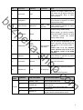
sh a- ek zp be HD Cube Network Camera Quick Start Guide o .c op m Version 1.0.2 Zhejiang Dahua Technology CO.,LTD Welcome be Thank you for purchasing our network camera! This quick start guide is designed to be a reference tool for your system. Please keep this start guide well for future reference. Please open the accessory bag to check the items one by one in accordance with the list below. Contact your local retailer ASAP if something is missing or damaged in the bag. Before your operation please read the following instructions carefully. 1.Electrical safety sh a- ek zp All installation and operation here should conform to your local electrical safety codes. The power shall conform to the requirement in the SELV (Safety Extra Low Voltage) and the Limited power source is rated 12V DC in the IEC60950-1. This series product supports PoE too. Please note: Do not connect these two power supplying sources to the device at the same time; it may result in device damage! We assume no liability or responsibility for all the fires or electrical shock caused by improper handling or installation. We are not liable for any problems caused by unauthorized modification or attempted repair. 2.Transportation security Heavy stress, violent vibration or water splash are not allowed during transportation, storage and installation. 3.Installation o .c 4.Qualified engineers needed op Do not apply power to the camera before completing installation. Please install the proper power cut-off device during the installation connection. Always follow the instruction guide the manufacturer recommended. All the examination and repair work should be done by the qualified service engineers. We are not liable for any problems caused by unauthorized modifications or attempted repair. 5.Environment m This series network camera should be installed in a cool, dry place away from direct sunlight, inflammable, explosive substances and etc. Please keep it away from the electromagnetic radiation object and environment. Please make sure the CCD (CMOS) component is out of the radiation of the laser beam device. Otherwise it may result in CCD (CMOS) optical component damage. Please keep the sound ventilation. Do not allow the water and other liquid falling into the camera. i Thunder-proof device is recommended to be adopted to better prevent thunder. The grounding studs of the product are recommended to be grounded to further enhance the reliability of the camera. 6. Daily Maintenance zp be Please shut down the device and then unplug the power cable before you begin daily maintenance work. Do not touch the CCD (CMOS) optic component. You can use the blower to clean the dust on the lens surface. Always use the dry soft cloth to clean the device. If there is too much dust, please use the water to dilute the mild detergent first and then use it to clean the device. Finally use the dry cloth to clean the device. Please put the dustproof cap to protect the CCD (CMOS) component when you do not use the camera. 7. Accessories ek Be sure to use all the accessories recommended by manufacturer. Before installation, please open the package and check all the components are included. Contact your local retailer ASAP if something is broken in your package. Amount Network Camera 1 Quick Start Guide 1 Installation Accessories Bag 1 CD 1 sh a- Accessory Name op Warranty Card and Certificate 1 o .c m ii Table of Contents 1 Structure ................................................................................................................................. 1 Device Components................................................................................................. 1 1.2 Dimensions ............................................................................................................... 3 1.3 Bidirectional talk ....................................................................................................... 3 be 1.1 zp 1.3.1 Device-end to PC-end....................................................................................... 3 1.3.2 PC-end to the Device-end ................................................................................ 3 1.4 Alarm Setup .............................................................................................................. 4 1.4.1 Alarm Input and Output Connection ................................................................ 4 Device Installation ................................................................................................................. 6 3 Quick Configuration Tool ...................................................................................................... 8 3.2 4 Overview ................................................................................................................... 8 sh a- 3.1 ek 2 Operation .................................................................................................................. 8 Web Operation ..................................................................................................................... 10 Network Connection............................................................................................... 10 4.2 Login and Main Interface ....................................................................................... 10 op 4.1 Appendix Toxic or Hazardous Materials or Elements ............................................................. 12 o .c m iii 1 Structure 1.1 Device Components You can refer to the following figure for component information. See Figure 1-1. sh a- ek zp be Figure 1-1 Please refer to the following sheet for detailed information. SN Port Name Indicator Connector Note When system boots up–Green light becomes on. indicator POWER / When system is upgrading – Green light flashes. Interval is 0.5s. op 1 Power light When system is alarming– Green light flashes. Interval is 0.2s. o .c Wire network connection-Red light is on. 2 Network indicator light NET / 3 Speaker / / Output audio signal. (This function is optional. For some series product only.) 4 White light / / Can activate motion detect, PIR human body movement detect, external alarm. Wireless network connectionGreen light is on. m 1 SN Port Name Indicator Connector Note Passive IR motion detect port. It can detect the IR object movement (such as human body or other heating object). PIR sensor PIR / 6 Microphone / / Micro SD Micro SD card slot be 5 7 Micro SD card Restore factory default setup. zp 8 Reset button Reset ek 9 Directly receive audio signal. (This function is optional. For some series product only.). SD card storage. (This function is optional. For some series product only.). WPS button Alarm pin 11 Power port Fast wireless connection Press the WPS button of the router and the device respectively for at least 2 seconds. Usually the device can connect to the router within 1 minute. Please note it is for wireless series product only and it is for the wireless router of the WPS function. Alarm signal input/output (This function is optional. For some series product only.). sh a- 10 WPS When system is running normally, press the RESET button for at least 5 seconds, system can restore factory default setup. / / I/O port DC12V / Input DC 12V power. op Connect to standard Ethernet 12 Network port LAN Ethernet port cable. Support PoE function. Cable SN Cable Port Name Function Description 1 ALARM_COM Alarm output public end. 2 ALARM_NO 3 Alarm output port. Output alarm signal to alarm device. NO: Normal open alarm output end. GND Ground end. 4 ALARM_IN Alarm input port. It is to receive the on-off signal from the external alarm source. m I/O Port o .c Port Name 2 1.2 Dimensions Please refer to the following figure for dimension information. The unit is mm. See Figure 1-2. sh a- ek zp be Figure 1-2 1.3.1 Device-end to PC-end Device Connection op 1.3 Bidirectional talk Listening Operation o .c Please connect the earphone to the audio output port in the PC. Login the Web and then click the Audio button to enable the bidirectional talk function. You can see the button becomes yellow after you enabled the audio talk function. Click Audio button again to stop the bidirectional talk function. Speak or play music at the device-end, you can use the earphone or the sound box of the PC-end to listen the audio information from the device-end. m 1.3.2 PC-end to the Device-end Device Connection Connect the speaker or the MIC to the audio input port in the PC. Login the Web and then click the Audio button to enable the bidirectional talk function. You can see the button becomes yellow after you enabled the audio talk function. Click Audio button again to stop the bidirectional talk function. Listening Operation Speak or play music at the PC-end, you can use the built-in speaker of the device-end to listen. 3 Note Please go to the Master Volume interface of the PC to set first if you want to use the dual-way bidirectional talk. Please select Front Mic mode in the record control interface. (You can select microphone enhanced in Advanced interface if the audio is too low.) 1.4 Alarm Setup sh a- ek zp be The alarm setup interface is shown as below. See Figure 1-3. Figure 1-3 1.4.1 Alarm Input and Output Connection o .c op Please follow the steps listed below for local alarm input and output connection. 1) Connect the alarm input device to the alarm input port of the I/O cable. 2) Connect the alarm output device to the alarm output port of I/O cable and alarm output public port. The alarm output port supports NO (normal open) alarm device only. 3) Open the Web, go to the Figure 1-3. Please set the alarm input and output port. Web alarm input corresponds to device I/O.Based on alarm input device signal of high or low level, set NO/NC input. 4) Set alarm output at Web end. Alarm output corresponds to device alarm output port, as alarm output port on I/O cable. m Please refer to the following figure for alarm input information. See Figure 1-4. Alarm input: When the input signal is idle or grounded, the device can collect the different statuses of the alarm input port. When the input signal is connected to the 3.3V or is idle, the device collects the logic “1”. When the input signal is grounded, the device collects the logic “0”. 4 be Figure 1-4 sh a- ek zp Please refer to the following figure for alarm output information. See Figure 1-5. Port NO and Port C composes an on-off button to provide the alarm output. This button is normal open. The button becomes off when there is an alarm output. Figure 1-5 o .c op m 5 2 Device Installation This series camera support two installation modes: wall mount and pendant mount. See Figure 2-1 and Figure 2-2. Important Please make sure the installation surface can min support the 3X weight of the camera and the bracket. be Step 1 Paste the installation positioning map on the installation surface such as wall, ceiling or the wood. Step 2 Dig holes in the installation surface according to the installation positioning map. sh a- ek zp op Figure 2-1 o .c Step 3 Insert the expansion bolts from the accessories bag to the holes you just dug. If it is the wood surface you can skip to the next step. Step 4 Use the screws from the accessories bag to secure the device firmly. Connect the cable and then boot up the device. Step 6 m Step 5 Loosen the adjust knob for a little bit, adjust the camera to proper surveillance position according to your actual requirements. Step 7 Secure the knob of the bracket to fix the camera. 6 sh aek zp be Figure 2-2 o .c op m 7 3 Quick Configuration Tool 3.1 Overview Quick configuration tool can search current IP address, modify IP address. At the same time, you can use it to upgrade the device. Please note the tool only applies to the IP addresses in the same segment. be 3.2 Operation Double click the “ConfigTools.exe” icon, you can see an interface is shown as in Figure 3-1. In the device list interface, you can view device IP address, port number, subnet mask, default gateway, MAC address and etc. sh a- ek zp Figure 3-1 o .c op Select one IP address and then right click mouse, you can see an interface is shown as in Figure 3-2. Select the “Open Device Web” item; you can go to the corresponding web login interface. m Figure 3-2 8 Figure 3-3 sh a- ek zp be If you want to modify the device IP address without logging in the device web interface, you can go to the configuration tool main interface to set. In the configuration tool search interface (Figure 3-1), please select a device IP address and then double click it to open the login interface. Or you can select an IP address and then click the Login button to go to the login interface. See Figure 3-3. In Figure 3-3, you can view device IP address, user name, password and port. Please modify the corresponding information to login. Please note the port information here shall be identical with the port value you set in TCP port in Web Network interface. Otherwise, you can not login the device. If you are using device background upgrade port 3800 to login, other setups are all invalid. After you logged in, the configuration tool main interface is shown as below. See Figure 3-4. o .c op Figure 3-4 m For detailed information and operation instruction of the quick configuration tool, please refer to the Quick Configuration Tool User’s Manual included in the resources CD. 9 4 Web Operation This series network camera products support the Web access and management via PC. Web includes several modules: Monitor channel preview, system configuration, alarm and etc. 4.1 Network Connection zp be Please follow the steps listed below for network connection. Make sure the network camera has connected to the network properly. Please set the IP address, subnet mask and gateway of the PC and the network camera respectively. Network camera default IP address is 192.168.1.108. Subnet mask is 255.255.255.0. Gateway is 192.168.1.1 Use order ping ***.***.***.***(* network camera address) to check connection is OK or not. 4.2 Login and Main Interface Open IE and input network camera address in the address bar. See Figure 4- 1. ek Input your IP address here sh ao .c op Figure 4- 1 The login interface is shown as below. See Figure 4- 2. Please input your user name and password. Default factory name is admin and password is admin. Note: For security reasons, please modify your password after you first login. m 10 ek zp be Figure 4- 2 sh a- After you successfully logged in, please install WEB plug-in unit. Please refer to the Web Operation Manual included in the resource CD for detailed operation instruction. See Figure 4- 3. o .c op m Figure 4- 3 11 Appendix Toxic or Hazardous Materials or Elements Toxic or Hazardous Materials or Elements Component Name Pb Hg Cd Cr VI PBB PBDE ○ ○ ○ ○ ○ ○ Device Case ○ ○ ○ ○ ○ ○ Wire and Cable ○ ○ ○ ○ ○ ○ ○ ○ ○ ○ ○ ○ ○ ○ ○ ○ ○ ○ Circuit Board Component zp be Packing Components Accessories ek O: Indicates that the concentration of the hazardous substance in all homogeneous materials in the parts is below the relevant threshold of the SJ/T11363-2006 standard. Note: sh a- X: Indicates that the concentration of the hazardous substance of at least one of all homogeneous materials in the parts is above the relevant threshold of the SJ/T11363-2006 standard. During the environmental-friendly use period (EFUP) period, the toxic or hazardous substance or elements contained in products will not leak or mutate so that the use of these (substances or elements) will not result in any severe environmental pollution, any bodily injury or damage to any assets. The consumer is not authorized to process such kind of substances or elements, please return to the corresponding local authorities to process according to your local government statutes. op This quick start guide is for reference only. Slight difference may be found in user interface. All the designs and software here are subject to change without prior written notice. All trademarks and registered trademarks mentioned are the properties of their respective owners. o .c If there is any uncertainty or controversy, please refer to the final explanation of us. Please visit our website or contact your local service engineer for more information. m Dahua Technology Co.,Ltd Address:No.1187 Bin’an Road, Binjiang District, Hangzhou, PRC. Postcode: 310053 Tel: +86-571-87688883 Fax: +86-571-87688815 Email:[email protected] Website: www.dahuatech.com 12