1
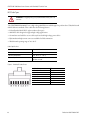
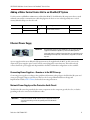
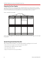
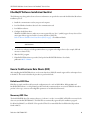
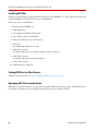
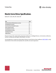
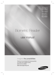
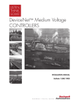
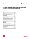
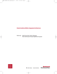
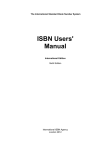
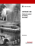
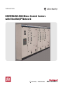
Technical Data
CENTERLINE 2500 Motor Control Centers
with EtherNet/IP Network
CENTERLINE 2500 Motor Control Centers with EtherNet/IP Technical Data
Table of Contents
Reference Materials. . . . . . . . . . . . . . . . . . . . . . . . . . . . . . . . . . . . . . . . . . . . . . . . . . . 2
Overview. . . . . . . . . . . . . . . . . . . . . . . . . . . . . . . . . . . . . . . . . . . . . . . . . . . . . . . . . . . . 3
EtherNet/IP Network Overview . . . . . . . . . . . . . . . . . . . . . . . . . . . . . . . . . . . . . . . . . . 3
EtherNet/IP Network in MCCs . . . . . . . . . . . . . . . . . . . . . . . . . . . . . . . . . . . . . . . . . . . 3
System Architecture . . . . . . . . . . . . . . . . . . . . . . . . . . . . . . . . . . . . . . . . . . . . . . . . . . . 3
Adding a Motor Control Center Unit to an EtherNet/IP System . . . . . . . . . . . . . . . . . 7
Ethernet Power Suppy . . . . . . . . . . . . . . . . . . . . . . . . . . . . . . . . . . . . . . . . . . . . . . . . . 7
System Design Installation Checklist. . . . . . . . . . . . . . . . . . . . . . . . . . . . . . . . . . . . . . 8
EtherNet/IP Software Installation Checklist . . . . . . . . . . . . . . . . . . . . . . . . . . . . . . . . 9
How to Find Electronic Data Sheets (EDS). . . . . . . . . . . . . . . . . . . . . . . . . . . . . . . . . . 9
Reference Materials
For additional CENTERLINE 2100 Motor Control Center data and general information, refer to the following
publications and websites.
Title
CENTERLINE 2100 Motor Control Centers Product Profile
Integrated Intelligence within an MCC—IntelliCENTER Product Profile
IntelliCENTER Software User Manual
Integrated, Intelligent Motor Control Centers White Paper
Joining and Splicing Vertical Sections Installation Instructions
EtherNet/IP Performance Application Solution
EtherNet/IP Modules in Logix 5000 Control Systems User Manual
NetLinx Selection Guide
Ethernet: Technology Enabler for Network Convergence White Paper
IntelliCENTER Technology
Motor Control Centers (MCC)
Electronic Publications
EtherNet/IP Network (Allen-Bradley)
EtherNet/IP Capacity Tool
Electronic Data Sheets (EDS) files
EtherNet/IP Media Planning and Installation Manual
2
Publication
2100-PP020
MCC-PP001
MCC-UM001
2100-WP001
2100-IN010
ENET-AP001
ENET-UM001
NETS-SG001
NETS-WP005
Website
Available Online at…
http://www.rockwellautomation.com/literature
http://www.ab.com/intellicenter
http://www.ab.com/mcc
http://www.rockwellautomation.com/literature
http://www.ab.com/networks
http://www.rockwellautomation.com/solutions/
integratedarchitecture/resources3.html
http://www.rockwellautomation.com/resources/
eds/
This manual is available from the Open
DeviceNet Vendor Association (ODVA) at
http://www.odva.org
Publication 2500-TD003A-EN-P
CENTERLINE 2500 Motor Control Centers with EtherNet/IP Technical Data
Overview
This document describes cable system construction and components associated with an EtherNet/IP network that is
factory installed in CENTERLINE 2500 and IntelliCENTER motor control centers (MCCs).
ATTENTION: Before performing any service or maintenance activities on MCC columns,
disconnect all power sources.
Follow local codes and guidelines in addition to the requirements of EN 50110.
EtherNet/IP Network Overview
The EtherNet/IP network offers a full suite of control, configuration, and data collection services by layering the
Common Industrial Protocol over the standard protocols used by the Internet (TCP/IP and UDP). The EtherNet/IP
network uses TCP/IP for general messaging and information exchange services, and UDP/IP for I/O messaging
services for control applications. This combination of well-accepted standards provides the functionality required to
support both information data exchange as well as control applications.
Another key feature of the EtherNet/IP network is that it uses commercial, off-the-shelf Ethernet components and
physical media. This provides a cost-effective plant floor solution by using a familiar and well-understood
infrastructure.
The EtherNet/IP network is most often used in these types of configurations:
• As an economical solution for connecting many computers
• As the best choice when you want to connect many devices
• As the standard network for connectivity to enterprise systems
• As the least expensive HMI option when used with PanelView Plus terminal
• In a star topology when nodes are grouped closely together
EtherNet/IP Network in MCCs
The EtherNet/IP network integrates with current IT networks. This document details the applications of the
EtherNet/IP network in MCCs, including cable system construction and common EtherNet/IP components.
System Architecture
When designing EtherNet/IP systems, it is necessary to consider the following factors:
• Connection count
• Cable type and lengths
Publication 2500-TD003A-EN-P
3
CENTERLINE 2500 Motor Control Centers with EtherNet/IP Technical Data
Connection Count
The EtherNet/IP network can accommodate a vast number of nodes. The EtherNet/IP network does not have a
specific maximum number of nodes like other fieldbus networks. The limit is based on the number of connections the
EtherNet/IP scanner can make.
The number of connections used by each node varies. To estimate the number of connections a network would use,
visit http://www.rockwellautomation.com/solutions/integratedarchitecture/resources3.html for our EtherNet/IP
Capacity Tool.
Cable Length Limitations
The EtherNet/IP network uses fiber or copper twisted-pair wiring. The maximum length of copper twisted-pair
wiring is 100 m between devices. There is no cumulative length for the entire network. Fiber cable length varies by
design of the cable. Inside the MCC, all cables are copper twisted-pair.
IMPORTANT
The 100 m maximum length has to account for Ethernet cable inside the column. There
is already up to three meters of cable from the Grace port on the power supply module
to the Ethernet switch. This cable length is added to the distance of the length
between the Grace port and the externally connected device.
Cable Routing
Figure 1. Typical Single MCC Column
Out to section on left.
Out to section on right.
Stratix 6000 Switch
3-phase Horizontal
Power Bus
4
Publication 2500-TD003A-EN-P
CENTERLINE 2500 Motor Control Centers with EtherNet/IP Technical Data
Each EtherNet/IP network has one or two Stratix 6000 switches that are always mounted in the top horizontal
wireway in the standard configuration. The number of switches depends on the number of units in the column. Cables
connected to the switch are then routed to EtherNet/IP connections in the network wireway. Up to 12 EtherNet/IP
ports can be provided in the network wireway.
In a standard MCC column, the vertical network wireway has EtherNet/IP connections equal to the number of units,
up to 12, for that column. Devices that require 24V DC to power up will have it supplied via the control plug via pins
B4 and B5. These pins are reserved for the 24V DC power and should not be used for other reasons.
Connection to the EtherNet/IP network and the control plug is made when a unit is in the Connected or Test
position.
The addition or removal of a unit from the EtherNet/IP system does not interrupt the operation of other units in the
system.
Figure 2. Typical Two-column Shipping Block
Stratix 6000
Switch
3-phase Horizontal
Power Bus
Determining Cable Lengths
To help determine cable lengths for your application, each MCC is shipped with documentation identifying the cable
length used within the MCC.
Publication 2500-TD003A-EN-P
5
CENTERLINE 2500 Motor Control Centers with EtherNet/IP Technical Data
MCC Cable Types
ATTENTION: Do not apply high voltage to any installed EtherNet/IP cable system or its
connectors.
The CENTERLINE 2500 MCCs use a high voltage 600V Ethernet cable designed to perform above TIA 568-B.2 and
ODVA Ethernet standards. These cables have the following features:
• Foil and braided shield, PVC, eight conductor (four pair)
• 600V PVC cable designed to support high voltage applications
• On-machine rated cable for use in a cable tray shared with high voltage power cables
• RJ45 insulation displacement connector available for field terminations
• Wide thermal operating range of -20…80 °C
Cable Specifications
Certifications
UL and cUL Listed
Outside diameter
0.32 ± 0.015 in. (8.13 ± 0.38 mm)
Operating temperature
-20…80 °C (-4…176 °F)
Cable Rating
UL, cUL TYPE CMG; UL PLTC or UL AWM 2570
80C 600V, TIA 568B
Figure 3. EtherNet/IP Cable Pin-out
1 - White/Orange
2 - Orange
3 - White/Green
4 - Blue
5 - White/Blue
6 - Green
7 - White/Brown
8 - Brown
6
TxData +
TxData Recv Data +
Unused
Unused
Recv Data Unused
Unused
Publication 2500-TD003A-EN-P
CENTERLINE 2500 Motor Control Centers with EtherNet/IP Technical Data
Adding a Motor Control Center Unit to an EtherNet/IP System
Use this section to add Bulletin 2500 units to an EtherNet/IP MCC. Each EtherNet/IP component is factory wired
within the unit and has a communication cable that plugs into the device on one end and generally into a vertical
wireway EtherNet/IP port on the other end.
No. of Conductors
Jacket Material
Cable Type
Cable Rating
Cat. No.(1)
8
Teal 600V PVC
Foil and braided
shield
(UL) CMX, CMR; c(UL) CMG; (UL) PLTC or AWM
2570 80 °C 600V; TIA-568-B
1585J-M8HBJM-2
Red 600V PVC
(1)
1585J-M8EBJM-2
Replace -2 (2 m) with -5 (5 m), or -10 (10 m) for additional standard cable lengths.
Ethernet Power Suppy
IMPORTANT
Many EtherNet/IP components require 24V DC power source to operate. The power
supply must be EtherNet/IP compatible as specified in the ODVA requirements.
Power supplies that do not satisfy both points listed above can result in damage to the
EtherNet/IP signal and components, as well as failure to comply with local codes and
inspection.
A power supply unit that meets EtherNet/IP requirements can be supplied with the MCC. A cable connects the
output of the power supply to pins C3 and C4 of the control plug in the network wireway. This cable is already
connected when the power supply unit ships installed in the MCC. Redundant configurations are also available.
Connecting Power Supplies—Remote or in the MCC Line-up
Connecting power supplies according to these guidelines will minimize voltage drops in the EtherNet/IP system and
ensure proper supply voltage to system devices. Refer to the Converged Plantwide Ethernet Design and
Implementation Guide, ENET-TD001, for detailed connecting instructions.
Network Power Supply and the Protective Earth Circuit
The EtherNet/IP network is grounded at the various components via the component ground; therefore, no further
grounding needs to be connected to the Ethernet cables.
IMPORTANT
It should be noted that the 24V DC common in the power supply bucket should not be
connected to the PE. Doing so violates the grounding in the various EtherNet/IP
components.
Publication 2500-TD003A-EN-P
7
CENTERLINE 2500 Motor Control Centers with EtherNet/IP Technical Data
Connecting Two Power Supplies
An additional 24V DC Class 1 power supply must be installed for MCC line-ups with approximately 14 columns.
When using two supplies, there should be a break between the two 24V DC networks. Locate the appropriate break
for the two networks and ensure the terminal blocks are not connected between these two columns.
Figure 4. Connecting Two Power Supplies
EtherNet/IP Network
24V DC Connection
-24V DC Connected
+24V DC Not Connected
24V DC Connection
Position each power supply to ensure that it feeds a maximum of seven columns to the left or right (refer to the sample
line-up below).
System Design Installation Checklist
When installing an EtherNet/IP MCC, use the following checklist before applying power to the network:
• Ensure only one power supply is connected for each 14 sections of MCC.
• Verify that the power supply for the system is 24V DC.
• Ensure that the PE is connected.
• Inspect connections for loose wires, opens, and shorts.
8
Publication 2500-TD003A-EN-P
CENTERLINE 2500 Motor Control Centers with EtherNet/IP Technical Data
EtherNet/IP Software Installation Checklist
The following steps, along with references for more information, are provided to assist with the EtherNet/IP software
installation process.
1. Install the communication card in your personal computer.
2. Load the Windows hardware drivers for the communication card.
3. Load RSLinx software.
4. Configure the RSLinx driver.
Within the RSWho function, make sure no unrecognized devices (the ‘?’ symbols) appear for any devices. If an
unrecognized device appears, load the electronic data sheet (EDS) file.
Refer to How to Find Electronic Data Sheets (EDS) on page -9 for additional details.
IMPORTANT
Do not leave the RSWho constantly browsing. Close the RSWho screen or
disable Autobrowse.
5. Use the device web pages or RSLogix 5000 software to program and configure devices (for example, full load
current, acceleration rate).
6. Write the PLC program.
7. If IntelliCENTER software is provided, load per the IntelliCENTER Software User Guide,
publication MCC-UM001.
How to Find Electronic Data Sheets (EDS)
After installing IntelliCENTER software, an electronic data sheet (EDS) file must be registered for each unique device
in the MCC. This section describes the procedure to perform this task.
Definition of EDS Files
EDS files are simple text files used by network configuration tools—such as RSNetWorx, RSLogix 5000, and
IntelliCENTER software—to help identify products and easily commission them on a network. EDS files describe a
product’s device type, revision, and configurable parameters on an EtherNet/IP network.
Necessary EDS Files
The IntelliCENTER data CD contains a directory (<cdrom>:\<order>\<item>\EDS) of EDS files necessary for the
devices in your IntelliCENTER MCC. The EDS files are automatically registered by the installation program.
For EtherNet/IP MCCs, an ‘EDS file’ CD is provided. This CD contains EDS files for all EtherNet/IP products
found in MCCs.
Publication 2500-TD003A-EN-P
9
CENTERLINE 2500 Motor Control Centers with EtherNet/IP Technical Data
Installing EDS Files
EDS files are installed with a program from Rockwell Software called ‘RSHWare.exe’. This program is included on the
IntelliCENTER data CD (in the same directory as the EDS files).
Follow these steps to install EDS files:
1. Run the program RSHWare.exe.
2. Click Add/Remove.
3. Select Register an EDS file and click Next.
4. Select Register a directory of EDS files.
5. Browse to the EDS directory on the data CD.
6. Click Next.
The Installer will display the test results.
7. Click Next to continue.
The Installer will allow you to change the graphic image for each device.
8. Click Next to continue.
The Installer will display the final task summary.
9. Click Next to continue.
10. Click Finish when completed.
Finding EDS Files for Other Devices
EDS files can be obtained at http://www.rockwellautomation.com/resources/eds/.
Uploading EDS Files from the Device
RSNetWorx for EtherNet/IP software can be used to upload an EDS file directly from a device. If an EDS file cannot
be found by other methods, refer to the RSNetWorx help file for steps to upload an EDS file.
10
Publication 2500-TD003A-EN-P
CENTERLINE 2500 Motor Control Centers with EtherNet/IP Technical Data
NOTES:
Publication 2500-TD003A-EN-P
11
Rockwell Automation, Rockwell Software, Allen-Bradley, CENTERLINE 2500, CENTERLINE 2100, IntelliCENTER, NetLinx, Integrated Architecture,
PanelView Plus, Stratix 6000, RSLinx, RSNetWorx, and RSNetWorx for EtherNet/IP are trademarks of Rockwell Automation, Inc.
Trademarks not belonging to Rockwell Automation are property of their respective companies.
Rockwell Otomasyon Ticaret A.Ş., Kar Plaza İş Merkezi E Blok Kat:6 34752 İçerenköy, İstanbul, Tel: +90 (216) 5698400
Publication 2500-TD003A-EN-P - March 2011 12
Supersedes Publication XXXX-X.X.X - Month Year
PN-XXXXX
Copyright © 2011 Rockwell Automation, Inc. All rights reserved. Printed in the U.S.A.