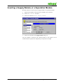
1
WAGO-I/O-CHECK
User Manual
Installation, Test and Start-up Functions
759-121/000-002
Version 1.0.1
Copyright ©2000 by WAGO Kontakttechnik GmbH
All rights reserved.
WAGO Kontakttechnik GmbH
Hansastraße 27
D-32423 Minden
Germany
Information:
Tel.: +49 (0) 571/8 87 – 0
Fax: +49 (0) 571/8 87 - 1 69
Support:
Tel.: +49 (0) 571/8 87 - 5 55
Fax: +49 (0) 571/8 87 - 4 30
E-mail: [email protected]
E-mail: [email protected]
Web: http://www.wago.com
Every conceivable measure has been taken to ensure the correctness and
completeness of this documentation. However, as errors can never be fully
excluded we would appreciate any information or ideas at any time.
We expressively point out that the software and hardware designations and brand
names of individual companies used in this user manual are subject to general
trade name, trade mark or patent protection.
Contents
Review
5
Scope of Delivery................................................................................................................ 5
Details in the User Manual .................................................................................................. 5
Concept ................................................................................................................. 5
Terms and Definitions........................................................................................... 6
Symbols................................................................................................................. 6
Font Conventions .................................................................................................. 6
Legal Stipulations ................................................................................................. 7
WAGO-I/O-CHECK ........................................................................................................... 8
Application............................................................................................................ 8
Function ................................................................................................................ 8
Warnings ............................................................................................................... 8
Supported Components ......................................................................................... 9
Non-Supported Components................................................................................. 9
Start
10
System Configuration........................................................................................................ 10
Installation......................................................................................................................... 11
Uninstall ............................................................................................................................ 11
Start ................................................................................................................................... 12
Start Menu........................................................................................................... 12
„Desktop“ - Windows Explorer ........................................................................ 12
Operation
14
File Menu .......................................................................................................................... 14
New..................................................................................................................... 14
Open.................................................................................................................... 15
Save..................................................................................................................... 16
Save As ............................................................................................................... 16
Print..................................................................................................................... 17
Print Preview....................................................................................................... 18
Print Setup........................................................................................................... 18
Properties ............................................................................................................ 19
Recent File .......................................................................................................... 21
Exit...................................................................................................................... 21
Edit Menu.......................................................................................................................... 22
Insert Supply or Separation Module.................................................................... 23
View Menu........................................................................................................................ 24
Zoom................................................................................................................... 24
Reduce................................................................................................................. 24
Enlarge ................................................................................................................ 24
Default................................................................................................................. 24
Toolbars .............................................................................................................. 25
WAGO-I/O-CHECK
Contents • iii
Connection Menu .............................................................................................................. 30
Online.................................................................................................................. 30
Offline ................................................................................................................. 30
Get Node Configuration...................................................................................... 31
Process Data........................................................................................................ 34
Diagnosis............................................................................................................. 42
Serial Interface Settings ...................................................................................... 43
Extras Menu ..................................................................................................................... . 44
Fieldbus Coupler Services................................................................................... 44
Help Menu......................................................................................................................... 46
Help Topics......................................................................................................... 46
Help Index........................................................................................................... 46
Context Help ....................................................................................................... 46
Using Help .......................................................................................................... 46
Info...................................................................................................................... 46
Function Keys and Key Combinations.............................................................................. 47
Node Testing with WAGO-I/O-CHECK
48
Warning Information......................................................................................................... 48
Important Information ....................................................................................................... 48
Communication Connection Configuration....................................................................... 49
Determining the Node Configuration ................................................................................ 50
Selecting an I/O Module.................................................................................................... 52
Display Process Data......................................................................................................... 53
Setting Outputs.................................................................................................................. 54
Digital Outputs.................................................................................................... 54
Analog Outputs ................................................................................................... 55
Inserting a Supply Module or a Separation Module.......................................................... 56
Glossary
57
Index
61
WAGO-I/O-CHECK
Contents • iv
Review
Scope of Delivery
WAGO-I/O-CHECK comprises of the following components:
• 1 pc user manual, English
Order No.:
759-121/000-002
• 1 pc communication cable
Order No.:
750-920
• 2 pcs installation disks
• 1 pc Software Licence Agreement
= Start-up tool BR 750
Order No.:
759-300/000-002
Details in the User Manual
This user manual documents the installation, functions and operation of
WAGO-I/O-CHECK.
Concept
Chapter Review of this user manual provides a review of the use and
possibilities of WAGO-I/O-CHECK.
The chapter Start contains a brief description of how to install and uninstall
WAGO-I/O-CHECK on your PC.
Finally, chapter Operation explains the menus, the toolbars and the dialogues
available to you to proceed with the installation on your screen.
The chapter Node testing with WAGO-I/O-CHECK shows you how to test
your fieldbus nodes with this start-up tool.
The Glossary contains important
WAGO-I/O-SYSTEM 750.
terms
and
abbreviations
of
the
The Index contains page numbers where the different key words appear.
This user manual does not detail the typical Windows menus and commands. For
help information to the general Windows surface, please refer to the pertinent
Windows manuals or Windows Online Help.
WAGO-I/O-CHECK
Review • 5
Terms and Definitions
This user manual uses the following abridged terms and definitions:
Term/Definition
Abridged form
Fieldbus node
Node
Fieldbus coupler
Coupler
Programmable fieldbus controller
Controller
These terms are explained in the glossary. Mentioning a coupler automatically
implies the controller. Certain functions which are exclusively valid for the
coupler or especially for the controller mention this fact.
Symbols
Texts of special importance are characterised by the following symbols and
additions:
Characterises important information for you to take into account
for a smooth start-up of your WAGO-I/O-CHECK.
Note:
Note characterises useful tips and information for you to use
when starting up WAGO-I/O-CHECK.
Font Conventions
WAGO-I/O-CHECK
Bold:
Instructions relating to the execution of actions and important
expressions are bold.
italic
Names of paths and files are identified in italic.
|
A vertical line between two names characterise the selection of a
menu point from a menu.
e. g.:
File|New
<>
Entries via the keyboard are within pointed brackets.
e. g.:
< F5 >
Courier
Menu points and names on command buttons are printed in the
Courier font.
e. g.:
OK
Review • 6
Legal Stipulations
This user manual including all of its illustrations is copyrighted, deviations from
the copyright stipulations are strictly prohibited. Reproduction, translation as
well as electronic and photographic archiving or changes require the written
approval of WAGO Kontakttechnik GmbH. Non observance will result in claims
for damage.
WAGO Kontakttechnik GmbH reserves all rights for changes or amendments
which serve technical progress. All rights for the issuing of patents or the
protection of registered designs are reserved by WAGO Kontakttechnik GmbH.
Products of other suppliers are always referred to without reference to patent
rights. For this reason the existence of such rights cannot be excluded.
The use of the product described in this user manual is solely intended for
qualified persons trained in PLC programming, qualified electricians or persons
instructed by qualified electricians who are also familiar with the applicable
standards and directives. WAGO Kontakttechnik GmbH declines all liability for
faulty operation and damages to WAGO products and products from other
suppliers resulting from non-observance of the information contained in this user
manual.
The components are delivered ex works with a defined hardware and software
configuration for each case of application. Changes are only permitted within the
framework of the possibilities outlined in the manuals. All other changes or
modifications to the hardware or software as well as the use of the components
not conforming with that intended will result in the exclusion from any liability
on the part of WAGO Kontakttechnik GmbH.
Please observe the supplied Software License Agreement „Allgemeine
Bedingungen zur Überlassung von WAGO-Software für Automatisierungszwecke“!
WAGO-I/O-CHECK
Review • 7
WAGO-I/O-CHECK
Application
WAGO-I/O-CHECK is an easy to use Windows application to operate and
represent a node from the WAGO-I/O-SYSTEM 750 without the need to
connect the node to a fieldbus system.
WAGO-I/O-CHECK was developed to be able to address individual nodes
during the start-up phase without having to rely on an active fieldbus system.
WAGO-I/O-CHECK
works
with
most
components
WAGO-I/O-SYSTEM 750 independent of the coupler used.
of
the
Function
WAGO-I/O-CHECK reads the configuration of a connected node from the
coupler and displays the node on the screen of your PC. The graphical
representation of the node can be printed out together with a configuration list.
WAGO-I/O-CHECK allows the display and default entry of process data of
individual I/O modules.
To ensure the communication between WAGO-I/O-CHECK and the node, the
coupler is connected to a free serial interface (port) of your PC using the
communication cable as part of our scope of delivery.
Warnings
•
Disconnect the node from the active fieldbus prior to processing the
process data with WAGO-I/O-CHECK.
Depending on the coupler setting, set outputs will be reset or remain set
after disconnection.
•
Outputs manually set with WAGO-I/O-CHECK (e.g. for motor
contactors or valves) remain set until they are manually reset.
Please note that in both cases switching off via the software, e. g. through
limit switches, has no effect!
WAGO-I/O-CHECK
Review • 8
Supported Components
WAGO-I/O-CHECK can be used to test nodes with couplers or controllers from
the WAGO-I/O-SYSTEM 750 for the following fieldbus systems:
•
CAN CAL
•
CANopen
•
DeviceNet
•
INTERBUS
•
LIGHTBUS
•
LON
•
MODBUS
•
PROFIBUS
WAGO-I/O-CHECK allows all coupler or controller and I/O module types from
the WAGO-I/O-SYSTEM 750 to be used for the representation of a node on the
screen and on paper.
Current process data of the following bus terminals blocks can be read out or
influenced:
•
All digital and analog input and output modules
•
Up /Down counter,
750-404
•
Input modules for thermocouples, 750-462, 750-469
•
Solid state relay module,
750-509
•
Pulse width output module,
750-511
•
Relay output module,
750-512, 750-513, 750-514, 750-517
•
Supply modules with diagnosis,
750-610, 750-611
Non-Supported Components
The following couplers and I/O modules do not permit to influence or read out
process data:
WAGO-I/O-CHECK
•
Couplers for digital signals, Profibus DP,
750-323
•
I/O modules for encoders and resolvers,
750-630, 750-631
•
Interface modules,
750-650, 750-651, 750-653, 750-654
Review • 9
Start
System Configuration
Minimum system requirements:
PC
486/100 MHz or better
WAGO-I/O-CHECK is designed to be used on a PC
with a 486 processor. We point out, however, that
efficient and economic work requires a Pentium
processor!
Operating system
Microsoft Windows 95 or better
Main memory
Windows 95: 16 MB or
Windows NT 4.0: 32 MB
For the graphic representation of the node, we
recommend to have your PC equipped with a higher
capacity main memory.
WAGO-I/O-CHECK
Fixed disk storage
recommended: 10 MB
Monitor
VGA or better, recommended: Super VGA
Resolution
Min. 640 x 480, Max. 1024 x 768
with a display of 256 colours
Mouse
required
Floppy disk drive
3.5“
Others
free serial interface, COM 1 ... 4
Start • 10
Installation
WAGO-I/O-CHECK comes on installation disks and contains all program files
required for the application. Installation of the programs does not differ from the
installation method used for most other Windows 95 or Windows NT
applications.
How to install WAGO-I/O-CHECK:
1.
If Windows 95 or Windows NT are not active, start your operating system
now.
2.
Insert the installation disk with the Installations disk 1 in your floppy disk
drive.
3.
Start the Windows Explorer and select the desired floppy disk drive. Start
the installation with a double click on the „Setup.exe“ file
or
select in the Start Windows menu the entry Run and enter the fixed disk
drive and the file name „Setup.exe“ in the entry field, e. g. „A:\Setup.exe“.
Start the installation by clicking the OK button.
4.
Carry out the screen-dialog instructions in order to conduct the installation.
Uninstall
How to uninstall WAGO-I/O-CHECK:
1.
Click on the Start symbol in the Windows task bar in order to open the
Start menu.
2.
Select the Programs option in the Start menu to be able to open the
Programs folder.
3.
Select Wago* to open the Wago* folder.
4.
Select WAGO-IO-CHECK* to be able to open the WAGO-IO-CHECK*
folder.
5.
Click on the WAGO-IO-CHECK uninstall link
6.
Follow the instructions on the screen to uninstall WAGO-I/O-CHECK
from your system.
* or the name you have selected
WAGO-I/O-CHECK
Start • 11
Start
WAGO-I/O-CHECK can be started in one of the following manners:
Start Menu
1.
Click on the Start symbol in the Windows task bar in order to open the
Start menu.
2.
Select the Programs option in the Start menu to open the Programs
folder.
3.
Select Wago* to open the Wago* folder.
4.
Select WAGO-IO-CHECK* in order to open the WAGO-IO-CHECK* folder.
5.
Click on the WAGO-IO-CHECK link.
* or the name you have selected
„Desktop“ - Windows Explorer
WAGO-I/O-CHECK can be started with the „Desktop“ symbol or the Windows
Explorer by a double click on the WagoCheck.exe file in the „WAGO-IOCHECK“ folder or by labelling the file and pressing the < Enter* > key. The
WagoCheck.exe file is on the drive and in the folder which you have entered at
the time of installation. If you have not changed the default settings when
installing, the WagoCheck.exe file is in the folder,
C:\Programme\Wago\WAGO-IO-CHECK
* or CR, ↵
The following start screen appears after starting:
WAGO-I/O-CHECK
Start • 12
Carefully read the following important information and confirm by clicking on
the OK button!
WAGO-I/O-CHECK
Start • 13
Operation
Menu Bar
WAGO-I/O-CHECK contains the following main menus:
File Menu
New
Use this command to logoff the node currently used and to initialise a new node.
To determine the denominations of the I/O modules of the connected node, use
the Get node configuration statement from the connection menu.
Shortcuts
Toolbar:
Keyboard:
WAGO-I/O-CHECK
< Ctrl > + < N >
Operation • 14
Open
Use this statement to open a saved node description.
Shortcuts
Toolbar:
Keyboard:
< Ctrl > + < O >
The following options allow you to enter the node description to be opened:
Look in
Select the drive and the folder in which WAGO-I/O-CHECK has saved
the node description which you want to open.
File name
Enter the file name or select the name from the list. This field only shows
files which correspond to the file extension you selected in the "File type"
field.
Files of type
Select the type of file to be opened:
WAGO-I/O-CHECK node description (*.wnd)
WAGO-I/O-CHECK
Operation • 15
Save
Use this command to save the active document under its current name and
directory. With the first saving of a document WAGO-I/O-CHECK displays the
dialog Save so that you can name your document.
Shortcuts
Toolbar:
Keyboard:
< Ctrl > + < S >
Save As
Use this command to name and save the opened node description. For this
WAGO-I/O-CHECK shows the dialog box Save As.
The following options permit you to enter the name and location of the node
description which you want to save:
Save in
Select the drive and the folder in which you want to save the node
description.
File name
Enter a new file name for the node description, so that the file can be
saved under a different name. WAGO-I/O-CHECK adds an extension to
the name you have assigned in the File type field.
Save as type
Select the type of file to be saved:
WAGO-I/O-CHECK node description (*.wnd)
WAGO-I/O-CHECK
Operation • 16
Print
Use this command to print the node description. The print dialog box appears
when selecting this command. Use this dialog box to select the page area to be
printed, the printer to be used and other options for printer setting can be
selected.
In addition to the node the print out also includes a list of the connected
components with their descriptions.
Shortcuts
Toolbar:
Keyboard:
Note:
WAGO-I/O-CHECK
< Ctrl > + < P >
The print out was optimised for DIN A4 in landscape format. For
an optimum print out do not change these settings!
Operation • 17
Print Preview
Use this command to display the nodes and the list of I/O modules used in the
same manner as they will be printed. When selecting this command the main
window is replaced by a print preview window in which one or two pages are
shown in print format. The toolbar of the print preview allows you to lay down
whether one or two pages are to be displayed simultaneously. In addition, you
can scroll up and down in a document, zoom in or out or start a print job.
Shortcut
Toolbar:
Print Setup
Use this command to define the printer and printer connection. The dialog box
Print setup appears after selecting the command. Use this dialog box to define
the printer and its connections.
WAGO-I/O-CHECK
Operation • 18
Properties
Use this command to display the node properties.
When selecting this command the dialog box Node info appears in which you
can enter a node name, station address and your company.
Property Sheet ‘File Info’
The following options in the property sheet ‘File Info’ provides information
about the saved file.
Symbol / file name
Shows the symbol and the file name of the node description.
Type
Identifies the file type.
Folder
Name of the drive and folder in which the file is saved.
Size
File size.
Created
Date and time for which the file was opened for the first time on this
computer.
Changed
Date and time when the file was last saved.
Opened
Date and time when the file was last opened.
WAGO-I/O-CHECK
Operation • 19
Property Sheet ‘Node Info‘
The following options in the property sheet ‘Node Info’ permit entering a more
detailed node: description
Title
Enter the node name. The name is entered in the title line of the page. The
title may deviate from the file name of the node description.
Station
Enter the station address or node subscriber. This information is entered in
the print out title line.
With Profibus couplers the setting of the coupler address selection
switches is shown. Do not change this value!
Termination (on/off)
Activate this checkbox if the node shown is the last node in your fieldbus
system and the termination is made on the hardware side. This setting is
entered on the headline of the print out.
Author
To change the name of the author delete the existing name enter a new
one. The name is entered in the headline of the print out.
Company
Enter the name of your company. The company name is entered in the I/O
module list when printing out the headline.
Comments
Enters an additional node comment. This comment is not printed.
WAGO-I/O-CHECK
Operation • 20
Recent File
List of the last node descriptions processed.
Exit
Use this command to exit from WAGO-I/O-CHECK. As an alternative you can
choose the command Close from the system menu. WAGO-I/O-CHECK asks
if you want to save files with changes not yet saved.
Shortcuts
Mouse:
Keyboard:
WAGO-I/O-CHECK
Click on the Close button in the title bar.
< Alt > + < F4 >
Operation • 21
Edit Menu
The commands Undo, Copy, Delete, Replace, Goto and Properties
are not available in this version.
Insert
WAGO-I/O-CHECK
Operation • 22
Insert Supply or Separation Module
The following dialog elements permit the insertion of a supply or separation
module in the view of a node:
A coupler does not recognise passive I/O modules. To display a node with
WAGO-I/O-CHECK it may also be helpful to subsequently insert an existing
passive I/O module in the graphic.
Selection list
Select an I/O module from the list using the order number.
Description
Shows the description of the selected I/O module.
Voltage
Level of the supply potential to be fed
Current via contacts
Maximum current, permitted to flow through the supply module
OK
Ends the dialog and inserts the selected I/O module into the graphic
Cancel
Ends the dialog without inserting an I/O module
Paste
The Paste command is not included in this version.
WAGO-I/O-CHECK
Operation • 23
View Menu
Zoom
Reduce
Use this command to reduce the node display size.
Shortcuts
Toolbar:
Keyboard:
<->
on the number block
Enlarge
Use this command to enlarge the node display size.
Shortcuts
Toolbar:
Keyboard:
<+>
on the number block
Default
Use this command to display the node on the screen in its original size.
Shortcuts
Toolbar:
Keyboard:
WAGO-I/O-CHECK
< Ctrl > + < D >
Operation • 24
Toolbars
The toolbars contain buttons allowing you a fast access to a large number of
commands and functions of WAGO-I/O-CHECK. When pointing with the
mouse on the button the corresponding name appears.
Standard Toolbar
The Standard toolbar contains the following buttons:
Button
Action
Close the node currently being used and initialise the new node.
Shows the Open dialog box.
Saves the opened node under its file name. If the file does not
already have a name WAGO-I/O-CHECK shows the dialog box
Save As.
Prints the node shown.
Shows a print preview with the nodes and a list of the I/O
modules.
Shows the mouse cursor for the context help.
WAGO-I/O-CHECK
Operation • 25
Communication Toolbar
The Communication toolbar contains the following buttons:
Button
Action
Reads out the designation of the I/O module of the connected
node.
Performs diagnosis of the coupler error code.
Creates an Online connection to the coupler.
Takes the coupler connection offline.
Zoom Toolbar
The Zoom toolbar contains the following buttons:
Button
Action
Reduces the screen display.
Enlarges the screen display.
Sets the screen display back to the default size.
WAGO-I/O-CHECK
Operation • 26
I/O Module Information Toolbar
The I/O Module Information toolbar contains the following elements:
Element
Action
This drop down field shows the position of the selected I/O
module and by selecting a position number allows a quick
change to a different I/O module.
This drop down field provides a description of the selected
I/O module and permits a quick change to a different I/O
module by selecting a description.
This drop down field shows the order number of the selected
I/O module and permits a quick change to a different I/O
module by selecting an order number.
WAGO-I/O-CHECK
Operation • 27
Toolbars can be relocated and toggled on and off.
Moving Toolbars
1 Click on the handle
toolbar.
of an docked toolbar or on the title bar of an undocked
2 Pull the toolbar to the required location. The toolbar is docked when pulling
over the edge of the user window.
Docked Toolbar
A toolbar docked to one side of the program window. A toolbar can be docked at
the left, right or bottom edge of the program window under the title bar. The
toolbar is docked to the edge of the screen if you pull a toolbar to the edge of the
program window.
Undocked Toolbar
A toolbar which is not docked to the edge of the program window. The toolbar is
docked to the edge of the screen when the toolbar is pulled to the screen edge.
Toggling on or off the Toolbar
WAGO-I/O-CHECK provides the following options for toggling on and off a
toolbar:
1 Click on a toolbar with the right hand mouse key. A context menu appears
with the existing toolbars. Select the toolbar which you want to toggle on or
off from this list. Once the toolbar is toggled on the corresponding menu
entry is checked.
2 Select the option Toolbars from the View menu. A menu listing the
available toolbars is shown. Select the toolbar which you want toggle on or
off from this list. When the toolbar is toggled on, a check appears next to the
corresponding menu entry.
3 To toggle off an undocked toolbar it is possible to click on the
the toolbar title bar.
WAGO-I/O-CHECK
symbol in
Operation • 28
Status Bar
The status bar is shown at the bottom edge of the WAGO-I/O-CHECK window.
The status bar can be toggled on or off in the menu View|Toolbars using
the Status Bar command.
1 As you move the DIRECTION KEYS by menus, the left hand area of the
status bar describes the function of the menu entries. In the same manner this
area also describes the effect of the toolbar buttons if these are pressed and
held. Release the mouse key when the mouse pointer is no longer on the
button if you do not want to perform the command associated with a toolbar
button after reading its description.
2 During certain program actions a description of the action and a progress
display showing the performance of the action appears in the left hand
section of the status bar:
3 The right hand area of the status bar shows the state of the connection to the
coupler:
Display
Description
Offline
Online
No data exchange with the coupler takes place.
WAGO-I/O-CHECK cyclically reads the process data of the
connected node.
In this case do not cut the connection !
The light diodes in the right hand section of the status bar have the following
meaning:
When both light diodes are switched off (grey), neither a node is read out nor a
data exchange performed between WAGO-I/O-CHECK and the coupler.
Green LED
Description
ON
The order number of the I/O modules was successfully read
out of the coupler.
The coupler connection is active.
FLASHING
In this case do not cut the connection !
Red LED
Description
ON
The order numbers of the I/O modules could not be read out of
the coupler.
An active connection to the coupler was interrupted without
the coupler being reset.
FLASHING
WAGO-I/O-CHECK
Operation • 29
Connection Menu
Online
Use this command to start the communication with the coupler, after having
determined its configuration with the Connection|Get
Node
Configuration command.
To display the data dialog box select an I/O module and then use the
Connection|Process Data command.
Do not simultaneously operate WAGO-I/O-CHECK with an active fieldbus
system! For this reason ensure that the node connected to the PC does not
communicate with a fieldbus!
Shortcuts
Toolbar:
Keyboard:
< F9 >
Offline
Use this command to stop the communication with the fieldbus coupler.
Note:
If necessary this command closes all data dialog boxes still open.
Shortcuts
Toolbar:
Keyboard:
< F10 >
Never interrupt the connection between the PC and the nodes prior to
stopping the communication with Connection|Offline!
WAGO-I/O-CHECK
Operation • 30
Get Node Configuration
Use this command to read out the designations of the I/O modules of the
connected node after starting WAGO-I/O-CHECK or after selecting the
File|New. menu
The types of I/O modules are automatically recognised by WAGO-I/O-CHECK
when reading out the node. Digital I/O modules must be specified by the user.
For this the dialog box Select digital I/O modules for each digital I/O module.
The display of the node on the screen is made as a tree structure in the left hand
side and as a graphic on the right hand side.
Shortcuts
Toolbar:
Keyboard:
Note:
WAGO-I/O-CHECK
< F5 >
A coupler cannot recognise passive I/O module. For the display of
a node, with WAGO-I/O-CHECK however, it may be helpful to
subsequently insert an existing passive I/O module in the graphic.
For this use the option Insert power supply module or
distance module from the Edit|Insert menu.
Operation • 31
Selecting Digital I/O Modules
In a coupler only the information about the type (input/output) and the number of
inputs/outputs of the I/O module is saved for digital I/O modules.
WAGO-I/O-CHECK recognises this information and offers the possibility to
more precisely describe the I/O modules using this dialog box. The selection list
only contains I/O modules which are suitable for the displayed position.
Position
Shows the
[1 ... 64].
position
of
the
recognised
digital
I/O
module
Description
Shows the description of the I/O module. First only the information is
shown which WAGO-I/O-CHECK has determined based on the data
from the coupler.
General description for all modules
Click this checkbox if you do not want to select any description from
the displayed and the following I/O modules. This dialog box is no
longer displayed for any further existing digital I/O modules. In this
case WAGO-I/O-CHECK uses the corresponding default description
for all digital I/O modules.
Default description
Select this radio button if you only want to use the default description
for the displayed I/O module. The dialog box is shown for the next
digital I/O module.
WAGO-I/O-CHECK
Operation • 32
Further details
Select this radio button if you want to use a detailed description for the
I/O module shown. The dialog elements for the selection of the detailed
description are activated. The dialog box is shown again for the next
digital I/O module.
Order number
Select the drop down field for the order number of the I/O module (e.g.
as printed on I/O module). The I/O module description is shown in the
description field.
Use only for this module
Select this radio button if you want to use the detailed description only
for the displayed I/O module (currently the only option).
Use for all modules of this type
Select this radio button if you want to use the detailed description for all
I/O modules in the node, which conform to the displayed I/O module
type (currently not available).
Binary spacer module
If a binary spacer module is present in a node, an additional I/O module is shown
for each two reserved inputs and outputs. The dialog box Select digital I/O
modules allows a specification of the types of these I/O modules.
WAGO-I/O-CHECK
Operation • 33
Process Data
Use this command to display the process data of a selected I/O module.
Shortcuts
Mouse:
Double click on the I/O module for which you want
to display the process data.
Keyboard:
< F6 > or
Select the I/O module using the keys
< Ctrl > + < Right arrow key >
< Ctrl > + < Left arrow key >
or
or the mouse, and press the key < Enter > when the
required I/O module is reached.
Note:
This command is not available when no node was read out or no
node description opened.
‘Process Data’ dialog box
The following dialog box is available for visualising the process data:
2 Channel Digital Input
•
The position of the selected I/O module and its order number are shown at
the title bar.
•
The checkboxes indicate the states of the individual digital inputs. When an
input is set, a check mark appears in the attendant checkbox.
Note:
WAGO-I/O-CHECK
The states of the digital inputs are also displayed in the pictorial
representation of the node by coloured light diodes.
Operation • 34
2 Channel Digital Output
•
The position of the selected I/O module and its order number are shown at
the title bar.
•
The checkboxes indicate the states of the individual digital outputs. When
the output is set a check mark appears in the attendant checkbox.
The following options are available to set or reset the outputs available:
•
Click with the mouse in the corresponding checkbox.
•
Select the corresponding checkbox using the key < Tab >. Using the
< Spacebar > you can now set or reset the attendant output.
Both actions directly affect the process image of the node! This means that
the attendant output is set as soon as the checkbox is clicked. To reset click
on the checkbox again.
With WAGO-I/O-CHECK manually set outputs (e.g. for motor contactors
or valves) which remain set until they are manual reset.
Please note that in this case switching off on the software side, e.g. with limit
switches, is ineffective!
Note:
WAGO-I/O-CHECK
The states of the digital outputs are shown in the pictorial display
by coloured light diodes. To change theses states click in the node
picture on the coloured light diodes.
Operation • 35
2 Channel Digital Output with Diagnosis
•
The position of the selected I/O module and its order number are shown at
the title bar.
•
The checkbox indicates the states of the individual digital outputs and its
diagnosis outputs. Once the output/input is set a check mark appears in the
attendant checkbox.
The following options are available for setting or resetting outputs:
•
Click with the mouse in the corresponding checkboxes.
•
Select the corresponding checkboxes using the < Tab > key. The attendant
output can be set or reset using the < Spacebar >.
Both actions directly effect the process image of the node! This means that
the attendant output is set as soon as the checkbox is clicked. To reset click
on the checkbox again.
With WAGO-I/O-CHECK manually set outputs (e.g. for motor contactors
or valves) which remain set until they are manual reset.
Please note that in this case switching off on the software side, e.g. with limit
switches, is ineffective!
Note:
WAGO-I/O-CHECK
The states of the digital outputs are shown in the pictorial display
of the node by coloured light diodes. To change these states click
in the node picture on the coloured light diodes.
Operation • 36
4 Channel Digital Input
•
The position of the selected I/O module and its order number are shown at
the title bar.
•
The checkboxes indicate the states of the individual digital inputs. Once the
input is set a check mark appears in the attendant checkbox
Note:
WAGO-I/O-CHECK
The states of the digital inputs are shown in the pictorial display of
the node by coloured light diodes.
Operation • 37
4 Channel Digital Output
•
The position of the selected I/O module and its order number is shown at the
title bar.
•
The checkboxes indicate the states of the individual digital outputs. Once an
output is set a check mark appears in the attendant checkbox.
The following options are available for setting or resetting outputs:
•
Click with the mouse in the corresponding checkbox.
•
Select the corresponding checkbox using the key < Tab >. The attendant
output can be set or reset using the < Spacebar >.
Both actions directly effect the process image of the node! This means that
the attendant output is set as soon as the checkbox is clicked. To reset click
on the checkbox again.
With WAGO-I/O-CHECK manually set outputs (e.g. for motor contactors
or valves) which remain set until they are manual reset.
Please note that in this case switching off on the software side, e.g. with limit
switches, is ineffective!
Note:
WAGO-I/O-CHECK
The states of the digital outputs are shown in the pictorial display
of the node by coloured light diodes. To change these states click
in the node picture on the coloured light diodes.
Operation • 38
2 Channel Analog Input
•
The position of the selected I/O module and its order number are shown at
the title bar.
•
The displays show the individual analog value in milliamps or volts.
•
The sliders show the position of the value within the measuring limits of the
I/O module.
•
Use the checkbox “HEX” to toggle between a hexadecimal and a decimal
view (milliamps, volts) of the process data.
4 Channel Analog Input
WAGO-I/O-CHECK
•
The position of the selected I/O module and its order number are shown in
the title bar.
•
The displays indicate the individual analog value.
•
The sliders show the position of the value within the measuring limits of the
I/O module.
•
Use the checkbox “HEX” to toggle between a hexadecimal and a decimal
view (milliamps, volts) of the process data.
Operation • 39
2 Channel Analog Output
•
The position of the selected I/O module and its order number are shown at
the title bar.
•
The edit controls show the last set analog value in milliamps or in volts.
Enter the value here which the attendant module at your output should show.
Note:
The new value is sent to the node first when pressing the
< Enter* > key.
* or CR, ↵
•
The output value can also be changed using the sliders
These actions directly affect the node process display! This means: As soon
as the slider position is changed the data is sent to the node. However,
under certain circumstances the slider will not display the new value
immediately.
•
Use the checkbox “HEX” to toggle between a hexadecimal and a decimal
view (milliamps, volts) of the process data.
Note:
WAGO-I/O-CHECK
If a hexadecimal value greater than 7FFF is entered for an analog
output, a fault message appears and the original value is retained.
Operation • 40
Up/Down Counter (1x32 Bit)
•
The position of the selected I/O module and its order number are shown at
the title bar.
•
The display fields show the current counter reading and the count direction
or status (gated) of the counter.
•
Using the Reset button the counter can be zeroed.
Note:
The counter reading is given as a hexadecimal value.
Up/Down Counter (2 x 16 Bit)
(Version 000-005)
•
The position of the selected I/O module and its order number are shown at
the title bar.
•
The display fields show the current counter readings and the count direction.
•
Using the Reset button the counters can be zeroed.
Note:
WAGO-I/O-CHECK
The counter reading is given as a hexadecimal value.
Operation • 41
Diagnosis
Use this command to evaluate the coupler error codes, which is also signalled by
the light diode I/O ERR on the coupler.
This command can also be performed without the node being read out in
advance.
The evaluation of error code can, under certain circumstances, take several
seconds.
Shortcuts
Toolbar:
Keyboard:
< F7 >
The following messages are shown depending upon the error code:
Message
Cause
No error
No error occurred
Coupler error
Error coupler
Module error (I/O):
Module at position ‘xy’
xy indicates the I/O module position at which the
error has been encountered at the input/outputs
Terminal bus error:
-Command error
An I/O module could not perform a command
-Data error or
interruption behind the
fieldbus coupler
The coupler could not transfer data to an internal
bus. Possibly the internal bus is interrupted after the
coupler
-Interruption next to
module at position ‘xy’
The internal bus is interrupted after the I/O module
at position xy
-Error during
communication with
module at position ‘xy’
A fault has occurred during communication with the
I/O module at position xy
Note:
WAGO-I/O-CHECK
If a fault has occurred in the node, the error code command is
to be performed after the start of WAGO-I/O-CHECK without the
node being read out in advance.
Operation • 42
Serial Interface Settings
Use this command to select a serial PC interface for communication with the
coupler. All other settings (baud rate, data bits, parity, stop bits and flow control)
are set as defaults for communication with the WAGO-I/O-SYSTEM 750 and
cannot be changed.
WAGO-I/O-CHECK shows the Serial Interface Settings dialog box, in which
you can make the required settings.
Shortcut
Keyboard:
< F8 >
To set the WAGO-I/O-CHECK serial interface, select an interface from the
attendant drop down list.
WAGO-I/O-CHECK
Operation • 43
Extras Menu
Fieldbus Coupler Services
Use this command to trigger special defined functions in the coupler.
Shortcut
Keyboard:
< F4 >
Reset fieldbus coupler
Triggers a software reset in the coupler.
With a software reset all digital outputs are reset and the analog outputs
are set to the minimum value!
Manufacturer settings (currently not available)
Sets the original parameters of the coupler.
Reset terminal bus
Causes the coupler to trigger an internal bus reset.
With internal bus reset all digital outputs are reset and the analog outputs
set to the minimum value!
WAGO-I/O-CHECK
Operation • 44
Reset configuration
Represents the configuration of the coupler, which was active prior to
the communication with WAGO-I/O-CHECK.
This button can only be selected when the communication has not been
correctly terminated, e.g. in the case of a cable breakage or a power loss
during communication.
The following buttons and displays are only visible for PROFIBUS
couplers.
Station
This field shows the current station address setting of a PROFIBUS
coupler, as set with the address selection switch on the coupling
housing.
Change station
This button starts the selection of a station address for the coupler. You
can now set the required address using the address selection switches.
The coupler transmits the set address to WAGO-I/O-CHECK until you
adopt the displayed value using the Apply button.
Apply station
Using this button the selection of a station address is concluded. The
value is displayed in WAGO-I/O-CHECK and taken over by the
coupler.
Note:
WAGO-I/O-CHECK
Once this button is actuated a software reset is triggered in the
coupler to take over the new station address in the coupler.
Operation • 45
Help Menu
Help Topics
Use this command to display the help list of contents. From this mask you can
change (go) into topics which will explain the use of WAGO-I/O-CHECK step
by step.
As soon as help is opened it is always possible to click the contents button and
return to the list of contents.
Help Index
Use this command to display the help list of contents. From this mask you can
change to topics which explain the use of WAGO-I/O-CHECK step by step.
Context Help
Use this command to receive help about a certain part of WAGO-I/O-CHECK.
When the "Context help" button is selected in the toolbar the mouse pointer
changes to an arrow with a question mark. Click at any point in the
WAGO-I/O-CHECK window, for example on a button in the toolbar. The help
topic covering the clicked element will appear.
Shortcut
Toolbar:
Keyboard:
< Shift > + < F1 >
Using Help
Use this command to obtain general instructions for the use of help.
Info
Use this command to display the copyright information and the version number
of your copy of WAGO-I/O-CHECK.
WAGO-I/O-CHECK
Operation • 46
Function Keys and Key Combinations
WAGO-I/O-CHECK
Function keys/
key combinations
Menu / Function
< Ctrl > + < N >
File|New
< Ctrl > + < O >
File|Open
< Ctrl > + < S >
File|Save
< Ctrl > + < P >
File|Print
< Alt > + < F4 >
File|Exit
< - > (Number pad)
Reduce
< + > (Number pad)
Enlarge
< Ctrl > + < D >
Default size
< Shift > + < F1 >
Context help
< F4 >
Extras|Fieldbus coupler services
< F5 >
Connection|Get node configuration
< F6 >
Connection|Process data
< F7 >
Connection|Diagnosis
< F8 >
Connection|Serial interf.settings
< F9 >
Connection|Online
< F10 >
Connection|Offline
< Ctrl > + < Right arrow >
Graphic node: Select next I/O module
< Ctrl > + < Left arrow >
Graphic node: Select previous I/O module
< Ctrl > + < Pos1 >
Graphic node: Select coupler
< Ctrl > + < End >
Graphic node: Select end module
< Ctrl > + < Down arrow >
Tree structure: Select next I/O module
< Ctrl > + < Up arrow >
Tree structure: Select previous I/O module
< Enter > or
< CR >
<↵>
Dialog box process data:
Send process data of a selected I/O module to the
node
< Tab > or
< →| >
Dialog box process data:
Select a checkbox
< Spacebar >
Dialog box process data:
Set / reset output
Operation • 47
Node Testing with
WAGO-I/O-CHECK
Prior to or during the start up of your node using WAGO-I/O-CHECK ensure
that the following information is adhered to:
Warning Information
•
Prior to handling the process data with WAGO-I/O-CHECK it is
necessary to disconnect the node from the active fieldbus.
Dependent upon the coupler setting, set outputs can be reset or remain
set when disconnecting.
•
Using the WAGO-I/O-CHECK manually set outputs (e.g. for motor
contactors or valves) remain set until manually reset.
Take note that in both cases switching off via the software, e.g. with limit
switches, is inactive!
Important Information
WAGO-I/O-CHECK
•
Prior to disconnecting a connected coupler ensure that its original
configuration is reset!
[Menu connections|Offline]
•
Never disconnect the PC from a coupler, if WAGO-I/O-CHECK is in
Online-condition!
•
Only for a node with MODBUS connection:
Set the coupler station switch to ‘00’.
•
Only for a node with CAN connection:
For couplers a COB-ID must be selected which is between 1 and 126.
•
For the start up of a node with programmable fieldbus controller it is
necessary to stop the program processing (cycle) in the controller (stop
state)! For this move the slider next to the configuration interface to the
middle setting.
Node Testing with WAGO-I/O-CHECK • 48
Communication Connection Configuration
The following work steps are necessary to make a communication connection:
If you also want to communicate with a node in an active fieldbus system
using WAGO-I/O-CHECK please note that the coupler must be
disconnected from the fieldbus system for the duration of the connection to
WAGO-I/O-CHECK.
WAGO-I/O-CHECK
•
Switch off the voltage supply of the coupler.
•
Interrupt the connection to the fieldbus.
•
Open the cover of the configuration interface of the coupler and connect it
with the attendant plug of the communication cable.
•
Connect the D-Sub plug of the communication cable to a free serial interface
of the PC.
•
Switch on the voltage supply of the coupler again.
•
Start WAGO-I/O-CHECK and select the command Comport in the
Connection menu.
•
Select the serial interface used in the Comport options dialog box and close
the dialog box with the OK button.
•
WAGO-I/O-CHECK can now communicate with the node.
Node Testing with WAGO-I/O-CHECK • 49
Determining the Node Configuration
After the program start WAGO-I/O-CHECK has an empty screen view.
You can determine the node configuration in the following manner:
1.
Using the command Connection|Get node configuration
2.
Using the Get node
communication toolbar
3.
With the aid of the function key < F5 >
configuration
button in the
If the connected node contains digital I/O modules, you are requested to specify
same.
WAGO-I/O-CHECK
Node Testing with WAGO-I/O-CHECK • 50
If a precise definition of the digital I/O modules is unimportant for you, select
the Default button The dialog box Selecting digital I/O modules will not be
displayed for any further I/O modules and the default designation will be
selected for the I/O modules.
Digital I/O modules cannot be specified at a later date!
The types of analog I/O modules are automatically recognised by
WAGO-I/O-CHECK when reading out the node.
The connected node is shown as a graphic in the right hand mask section and as
a tree structure in the left hand mask section.
Note:
WAGO-I/O-CHECK
Passive power supply modules and distance modules are not
recognised by the bus coupler and can thus not be automatically
shown in WAGO-I/O-CHECK. The system allows to manually
insert these I/O modules in the graphic.
Node Testing with WAGO-I/O-CHECK • 51
Selecting an I/O Module
To select an I/O module, WAGO-I/O-CHECK provides the following methods:
•
Click the required I/O module with the mouse.
•
Select the next I/O module using the keys < Ctrl > + < right arrow >.
•
Select the previous I/O module using the keys < Ctrl > + < left arrow >.
•
Select the coupler using the keys < Ctrl > + < Pos1 >.
•
Select the end module using the keys < Ctrl > + < End >.
Tree view
•
Click on the entry for the required I/O module with the mouse.
•
Select the next I/O module using the key < Down arrow >.
•
Select the previous I/O module using the key < Up arrow >.
•
Select the coupler using the key < Pos1 >.
•
Select the end module using the key < End >.
Toolbars
•
WAGO-I/O-CHECK
Select the required I/O module in a drop down field at the toolbar
I/O Module Information.
Node Testing with WAGO-I/O-CHECK • 52
Display Process Data
The following possibilities are available to display the process data in
WAGO-I/O-CHECK:
Select an I/O module and
• select the Process data command in the Connection menu
•
actuate the key < F6 > or
•
actuate the enter key
Without selecting an I/O module the process data can be displayed
•
by double clicking on an I/O module or
•
by double clicking on the channel of an I/O module in the tree structure
Once one of these functions has been executed a dialog box appears with a
checkbox for each channel of the selected I/O module. The checkboxes indicate
the states of the individual digital inputs or outputs. If an input or an output is set
a check mark appears in the attendant checkbox. For analog inputs or outputs the
set values are displayed by the position of the slider and shown in display fields.
Example: digital inputs
Example: analog inputs
The states of the digital inputs and outputs are also shown in the picture section
of the node by coloured LED’s.
The dialog box always appear at the same position on the screen. To display the
process data of several I/O modules, the dialog boxes can therefore be moved
with the mouse.
WAGO-I/O-CHECK
Node Testing with WAGO-I/O-CHECK • 53
Setting Outputs
Digital Outputs
To set or reset digital outputs in WAGO-I/O-CHECK the following alternatives
are available:
•
Display the process data of an I/O module as previously described.
Click in the corresponding checkbox with the mouse or
Select the corresponding checkbox using the < Tab > key. Using the
< Spacebar > you can now set or reset the attendant output.
•
To change the states of the digital outputs you can also click on the node
pictorial display directly on the coloured LED’s (see next illustration).
The above mentioned actions act directly on the process image of the node!
This means that the attendant output is set as soon as you click in a
checkbox or on a light diode. Click in the checkbox or on an LED to reset
the outputs.
Outputs manually set with WAGO-I/O-CHECK (e.g. for motor contactors
or valves) remain set until they are manually reset again.
Please note that in this case switching off via the software, e.g. with limit
switches is ineffective!
WAGO-I/O-CHECK
Node Testing with WAGO-I/O-CHECK • 54
Analog Outputs
To change the values of analog outputs the following possibilities are available:
•
In the edit control enter a value in milliamps or volts, which the attendant
terminal output should provide. The new value is not sent to the node until
the <Enter* > key is pressed.
•
* or CR, ↵
Use the checkbox “HEX” to toggle between a hexadecimal and a decimal
view (milliamps, volts) of the process data.
If a hexadecimal value greater than 7FFF is entered for an analog output, a
fault message is transmitted and the original value is retained.
•
Use the sliders to change the output value.
This action directly affects the process image of the node! This means that
as soon as the position of the slider is changed the data is immediately sent
to the node. However, under certain circumstances the new value is not
displayed immediately by the slider.
WAGO-I/O-CHECK
Node Testing with WAGO-I/O-CHECK • 55
Inserting a Supply Module or a Separation Module
Proceed as follows to insert a passive supply module or a separation module:
1.
Select the I/O module, where the new I/O module is to be inserted.
2.
Select Edit/Insert sub-menu.
3.
Select the command Insert supply module.
4.
Select an I/O module in the Supply module dialog box
The I/O module is inserted in the selected position in the graphic, all I/O
modules from this position are displaced by one position to the right.
WAGO-I/O-CHECK
Node Testing with WAGO-I/O-CHECK • 56
Glossary
The following is an explanation of important terms
WAGO-I/O-SYSTEM 750 system which are used in this manual.
of
the
Analog input module
for 0 - 20 mA or 4 - 20 mA has the task to supply the measuring transducers
located in the field and to transmit analog measuring signals, which have to be
isolated, to the bus system. .
The analog input module for 0-10 V or ±10 V is used for the isolated
transmission of the input signal to the system level.
Analog output module
serves for passing on an analog signal from the automation unit to a connected
actuator. The analog output modules generate signals of the standardised levels
0-20 mA, 4-20 mA, 0-10 V or ±10 V depending upon the type.
Binary spacer module
reserves bit addresses for the inputs and outputs in a node.
Communication cable
Connection line between PC (serial interface COM) and fieldbus coupler or
programmable fieldbus controller (Configuration interface)
Controller
Abbreviation for programmable fieldbus controller
Coupler
Abbreviation for fieldbus coupler
Digital input module
serves for recording the digital control signal from the field area e.g. via sensors
or switches.
Digital output module
serves for transferring a digital control signals from the automation unit to a
connected actuator.
WAGO-I/O-CHECK
Glossary • 57
End module
is always the last module in a node. It closes the internal bus and permits
internal communication. The end module is absolutely necessary. It does not
have I/O functions.
Fieldbus coupler
(Abbreviation: coupler) represents the link between the fieldbus used and the I/O
modules. All necessary control tasks for further operation of the I/O functions
are performed by the fieldbus coupler.
Fieldbus node
(Abbreviation: node) comprises in all cases of a coupler or a Controller as head
station, a number of I/O modules and an End module, which forms the
conclusion.
Input module for resistance sensors
permits the direct connection of Pt and Ni resistance sensors. The connection can
be made using 2 or 3 conductor technology. The linearisation over the full
temperature range is realised by a micro-processor.
Input module for thermocouples
permits the direct connection of two thermocouples. The linearisation over the
full temperature range is realised by a micro-processor.
Interface module
RS232:
permits the connection of units with an RS232
interface to the WAGO-I/O-SYSTEM 750.
RS485:
permits the connection of units with an RS485
interface to the WAGO-I/O-SYSTEM 750.
TTY:
permits the connection of units with a 20 mA current
interface.
Data exchange module:
permits the exchange of 4 (5) bytes between various
fieldbus systems by multiplexers via a serial
connection.
I/O module
serves for the input and output of process data. Corresponding to the varying
requirements I/O modules for varying tasks are available. There are active and
passive I/O modules.
Active I/O modules have a process image for inputs and/or outputs. This
includes:
• Binary spacer module
• Digital and analog input modules
• Digital and analog output modules
• Input modules for resistance sensors
• Input modules for thermocouples
• Interface modules
• I/O modules for encoders and resolvers
• Pulse width output modules
• Relay output modules
• Solid state relay modules
• Supply modules with fuse holder / diagnosis
WAGO-I/O-CHECK
Glossary • 58
•
Up/Down counter
•
•
•
•
•
Passive I/O modules have no process image, this includes:
End module
Potential multiplication module
Separation module
Supply modules without diagnosis
I/O module for encoders and resolvers
Incremental encoder interface: The module represents an interface for
connecting optional incremental encoders.
SSI generator interface:
The module represents an interface for the
direct connection of an SSI generator.
Node
Abbreviation for fieldbus node
Potential multiplication module
serves for multiple power tapping of the supply voltage.
Programmable fieldbus controller
(Abbreviation: Controller)
WAGO fieldbus coupler with PLC function for
•
Signal pre-processing
•
Defined reaction in case of fieldbus failure
•
Decentral intelligence
The programmable fieldbus controller corresponds to the international standard
for control programming, IEC 1131-3 or the corresponding European standard
EN 61131-3, in all 5 languages: IL, LD, FBD, ST and SFC.
Pulse width output module
serves for the modulation of 16 Bit information in the pulse width. The
transmission to the field side is made isolated.
Relay output module
is a digital output module with a relay output. Using this I/O module a control
signal is passed from the automation unit to a connected actuator.
Separation module
serves to spatially separate various potentials within a node
Software reset
The coupler undertakes a reset and runs through its initialisation routines. All
coupler tables are rebuilt. In the case of a software reset all digital outputs of a
node are reset and the analog outputs are set to the minimum value
(e.g. at 4-20 mA to 4 mA).
Solid state relay module
is a digital output module with semi-conductor output. Using this I/O module a
control signal is passed from the automation unit to a connected actuator.
WAGO-I/O-CHECK
Glossary • 59
Supply module
serves to supply the I/O modules with the individual supply potential.
Supply module with fuse holder / diagnosis
serves to supply the I/O modules with individual supply potential.
The power supply module is protected by a fuse. A fuse defect is signalled by an
LED. To monitor the supply the module signals the status of the power supply
module to the coupler by two input bits .
Terminal bus
Internal communication between fieldbus coupler or programmable fieldbus
controller and the I/O modules, as well as the supply for the I/O modules.
Terminal bus reset
initialises the internal bus communication from the coupler to the plugged I/O
modules. A test sequence is run through with varying functions (e.g.. test
terminal row closed). With an terminal bus reset all digital outputs of a node are
reset and the analog outputs are set to the minimum value (e.g. 4...20 mA to
4 mA).
Up/Down counter
counts binary impulses from 24 V DC and transports the counters reading to the
initialised bus system.
WAGO-I/O-SYSTEM 750
comprises of various components used to build modular and user specific
fieldbus nodes for varying fieldbusses.
WAGO-I/O-CHECK
Glossary • 60
2 channel digital input 34
2 channel digital output 35
2 channel digital output with diagnosis 36
4 channel analog input 39
4 channel digital input 37
4 channel digital output 38
Up/Down counter (1 x 32 Bit) 41
Up/Down counter (2x16 Bit) 41
Digital input module 9, 34, 37, 57
Digital output module 9, 35, 38, 57
Digital output module with diagnosis 36
Index
E
End module 58, 59
F
Fieldbus coupler 6, 58
Fieldbus node 6, 58
File info 19
Fixed disk storage 10
Floppy disk drive 10, 11
A
Activ I/O module 58
Analog input module 9, 39, 57
Analog output module 9, 40, 57
B
Binary spacer module 33, 57, 58
C
CAN 9, 48
CAN CAL 9
CANopen 9
Communication cable 5, 8, 49, 57
Configuration interface 48, 49
Context help 25, 46, 47
Controller 6, 57
Coupler 6, 8, 9, 23, 29, 30, 31, 32, 42, 44, 45, 48, 49, 57
750-323 9
D
Data exchange module 58
DeviceNet 9
Dialog box
Fieldbus coupler services 44
File info 19
Insert supply or separation module 23, 56
Node info 20
Open 15
Print 17
Print setup 18
Process data 34, 35, 36, 37, 38, 39, 40, 41, 53, 54, 55
Save as 16
Selecting digital I/O modules 32, 50
Dialog box process data
2 channel analog input 39
2 channel analog output 40
WAGO-I/O-CHECK
I
I/O module 8, 9, 14, 18, 23, 25, 26, 27, 29, 30, 31, 32, 33,
42, 50, 52, 56, 58, 60
750-404 9
750-462 9
750-469 9
750-509 9
750-511 9
750-512 9
750-513 9
750-514 9
750-517 9
750-610 9
750-611 9
750-630 9
750-631 9
750-650 9
750-651 9
750-653 9
750-654 9
I/O module for encoders and resolvers 9, 58, 59
Incremental encoder interface 59
Input module for resistance sensors 58
Input module for thermocouples 9, 58
Installation disk 5, 11
INTERBUS 9
Interface module 9, 58
L
LIGHTBUS 9
LON 9
M
Main memory 10
Menu bar 14
Menu Edit
Copy 22
Index • 61
Delete 22
Goto 22
Paste 23
Properties 22
Replace 22
Undo 22
MODBUS 9, 48
Mouse 10
N
Node 6, 8, 9, 18, 19, 20, 23, 24, 25, 30, 31, 33, 48, 49, 50,
59
Node description 15, 21, 34
Node info 20
O
Operating system 10
Order number 5, 23, 29, 33
P
Passive I/O module 23, 59
PC 10
Potential multiplication module 59
PROFIBUS 9, 20, 45
Programmable fieldbus controller 6, 59
Pulse width output module 9, 58, 59
R
Relay output module 9, 58, 59
Reset fieldbus coupler 44
Reset terminal bus 44
Resolution 10
RS232 58
RS485 58
Software License Agreement 5, 7
Software reset 59
Solid state relay module 9, 58, 59
SSI generator interface 59
Start screen 12
Start-up tool BR 750 5
Station 45
Station address 19, 20
Status bar 29
Supply module 9, 23, 56, 60
Supply module with fuse holder / diagnosis 58, 60
Supply module without diagnosis 59
T
Terminal bus 60
Toolbar 25
Communication 26
Docked toolbar 28
I/O module information 27
Moving toolbar 28
Standard 25
Toggle on/off toolbar 28
Undocked toolbar 28
Zoom 26
TTY 58
U
Up/Down counter 9, 41, 59, 60
W
WagoCheck.exe 12
WAGO-I/O-SYSTEM 750 8, 9, 43, 60
Work steps 49
S
Separation module 23, 56, 59
Setup.exe 11
WAGO-I/O-CHECK
Index • 62