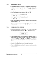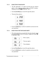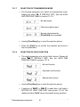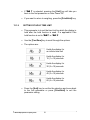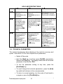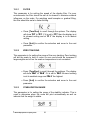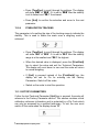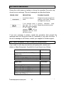
1
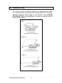
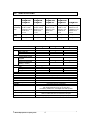
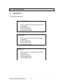
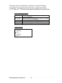
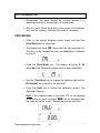
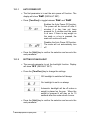
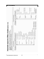
Adam Equipment CPWplus plus RANGE OF SCALES (P.N. 9009, Rev. C1, September 2010) © Adam Equipment Company 2010 © Adam Equipment Company 2010 CONTENTS 1.0 INTRODUCTION ............................................................................................. 3 2.0 SPECIFICATIONS ........................................................................................... 4 3.0 INSTALLATION ............................................................................................... 5 3.1 UNPACKING................................................................................................ 5 3.2 LOCATING................................................................................................... 6 3.3 SETTING UP................................................................................................ 7 3.3.1 SETTING UP THE STANDARD CPWplus SERIES............................... 7 3.3.2 SETTING UP THE CPWplus M & CPWplus L SERIES .......................... 8 4.0 KEYPAD .......................................................................................................... 9 5.0 DISPLAY.......................................................................................................... 9 6.0 SYMBOLS AND INDICATORS........................................................................ 9 7.0 BATTERY ...................................................................................................... 10 8.0 BACKLIGHT .................................................................................................. 10 9.0 AUTO POWER OFF ...................................................................................... 10 10.0 OPERATIONS ............................................................................................... 11 10.1 SWITCHING ON THE SCALE ................................................................... 11 10.2 ZEROING................................................................................................... 11 10.3 TARING...................................................................................................... 12 10.4 SELECTING THE UNIT ............................................................................. 13 10.5 WEIGHING ................................................................................................ 13 11.0 RS-232 INTERFACE ..................................................................................... 13 12.0 CALIBRATION............................................................................................... 15 13.0 PARAMETER SETTING................................................................................ 16 13.1 USER PARAMETERS................................................................................ 16 13.1.1 AUTO POWER OFF ........................................................................... 17 13.1.2 SETTING OF BACKLIGHT ................................................................. 17 13.1.3 ENABLING OF UNITS ........................................................................ 18 13.1.4 COMMUNICATION ADDRESS........................................................... 18 13.1.5 SELECTION OF BAUD RATE ............................................................ 19 13.1.6 SELECTION OF BIT RATE AND PARITY .......................................... 19 13.1.7 SELECTION OF TRANSMISSION MODE.......................................... 20 13.1.8 SELECTION OF HOLD FUNCTION ................................................... 20 13.1.9 SETTING OF HOLD TIME LIMIT........................................................ 21 13.2 TECHNICAL PARAMETERS ..................................................................... 22 13.2.1 FILTER................................................................................................ 23 13.2.2 ZERO TRACKING............................................................................... 23 13.2.3 STABILIZATION RANGE.................................................................... 23 13.2.4 STABILIZATION TRACKING .............................................................. 24 13.3 FACTORY PARAMETERS ........................................................................ 24 14.0 ERROR MESSAGES..................................................................................... 25 15.0 REPLACEMENT PARTS AND ACCESSORIES .......................................... 25 16.0 SERVICE INFORMATION ............................................................................ 26 17.0 WARRANTY INFORMATION ....................................................................... 27 18.0 APPENDIX.................................................................................................... 28 © Adam Equipment Company 2010 1 © Adam Equipment Company 2010 2 1.0 INTRODUCTION The CPWplus range of Platform Scales has a stainless steel top pan on a steel frame and an indicator with a large backlit LCD. The waterresistant keyboard has 4 easy to use function keys: [On/Off], [Print/Hold], [Unit], and [Tare/Zero]. All scales are supplied with the Power Supply module. CPWplus 300 x 300mm base operates with 6 x AA size batteries CPWplus M 500 x 500mm base with internal rechargeable batteries CPWplus L 900 x 600mm base with internal rechargeable batteries © Adam Equipment Company 2010 3 2.0 SPECIFICATIONS Model Capacity x Readability d=e= Repeatability Linearity CPWplus plus 35 plus 35M CPWplus CPWplus plus 35L CPWplus plus 75 plus 75M CPWplus CPWplus plus 75L CPWplus plus 150 plus 150M CPWplus CPWplus plus 150L CPWplus plus 200 plus 200M CPWplus CPWplus plus 200L CPWplus plus 300L 35 kg x 0.01kg 75 lb x 0.02 lb 1200 oz x 0.5 oz 74 lb:16 oz x 1 oz 0.01 kg / 0.02 lb 75 kg x 0.02 kg 165 lbx 0.05 lb 2640 oz x 1 oz 164 lb:16 oz x 1 oz 0.02 kg / 0.05 lb 150 kg x 0.05 kg 330 lb x 0.1 lb 5280 oz x 2 oz 329 lb:16 oz x 2 oz 0.05 kg / 0.1 lb 200 kg x 0.05kg 440 lb x 0.1 lb 7040 oz x 2 oz 439 lb:16 oz x 2 oz 0.05 kg / 0.1 lb 300 kg x 0.1kg 660 lb x 0.2 lb 10560oz x 5 oz 659 lb:16 oz x 5 oz 0.1 kg / 0.2 lb 0.02 kg / 0.04 lb 0.04 kg / 0.1 lb 0.10 kg / 0.2 lb 0.10 kg / 0.2 lb 0.2 kg / 0.4 lb Series Platform size 300 x 300 mm 500 x 500 mm 900 x 600 mm Power Option Power supply module supplied 6 x AA size batteries Internal rechargeable battery (~ 60 hrs) Net weight 4 kg 8.5 kg 17 kg Indicator Dimensions (wxdxh) Stabilization time Tare Weighing units Calibration Interface Operating temperature Humidity Display Keypad Scale housing Applications © Adam Equipment Company 2010 CPWplus plus CPWplus plus - M CPWplus plus - L 12 VAC 150 mA 12 VDC 500 mA 12 VDC 500 mA 220 x 95 x 43 mm 2 - 3 seconds Full range tare by subtraction kg, lb, oz, lb:oz Automatic External - user selectable cal weight Bi-directional RS-232 0°C to 40°C Up to 90% RH non-condensing 25 mm Backlit LCD digits with weight legends for kg, lb, oz, lb:oz and low battery, stable, zero, net weight and Hold symbols Mechanical switches under overlay Indicator: Aluminium Platform: Mild steel base and stainless steel pan Weighing, Dynamic / Animal weighing, Display Hold 4 3.0 INSTALLATION 3.1 UNPACKING The scales come with- Standard CPWplus CPWplus Indicator with bracket and 2 screws The Platform Stainless Steel Pan Power supply Module An Instruction manual CPWplus M CPWplus Indicator with bracket and 2 screws The Platform Stainless Steel Pan Power supply Module An Instruction manual CPWplus L CPWplus Indicator with bracket and 2 screws The Platform Stainless Steel Pan Power supply Module An Instruction manual © Adam Equipment Company 2010 5 3.2 LOCATING • The scales should not be placed in a location that will reduce the accuracy. • Avoid extremes of temperature. Do not place the scale in direct sunlight or near air conditioning vents. • Avoid unsuitable surfaces. The table or floor should be rigid and free from vibration. • Avoid unstable power sources. Do not use the scale near large users of electricity such as welding equipment or large motors. • Do not place the scale near vibrating machinery. • Avoid high humidity that might cause condensation. Avoid direct contact with water. Do not spray or immerse the scales in water. • Avoid air movement such as from fans or opening doors. Do not place the scale near open windows or air-conditioning vents. • Keep the scales clean. Do not stack material on the scales when they are not in use. © Adam Equipment Company 2010 6 3.3 SETTING UP 3.3.1 SETTING UP THE STANDARD CPWplus plus SERIES 1 Remove the parts from the packing carefully. Place the base on a rigid surface. Place the Stainless Steel pan on the base, if it not already assembled. 2 The indicator is separately packed and comes attached to a bracket with the help of two thumb screws. Bracket Thumb Screw To adjust the angle of the indicator, use the two thumb screws on the side of the bracket that connects the indicator. 3 Where applicable connect the cable attached to the base to the connector at the rear of the indicator. Tighten the ferrule to secure the cable. 4 Power can be supplied using the adapter delivering 12 VAC 150 mA minimum or using batteries inside the scale unit (6 x AA size). Remove the cover from the battery compartment under the scale. Install six AA size batteries as shown below. Connector on the Indicator The alkaline batteries are suggested for use for best life. 6 X "AA" Alkaline Connector attached to the cable Ferrule NOTE: When moving the scale, take care to prevent bending of the cable and connector too much as over a period of time this can weaken the wires in the connector and cause malfunction. MOUNTING THE INDICATOR- The indicator attached to the bracket can be mounted in the following 3 ways. To adjust the angle of the indicator, use the two thumb screws on the side of the bracket that connects the indicator. 1. Place it on the work bench- Simply place the indicator attached to the bracket on the work bench at an angle. 2. Attach it to the base of the scale- There are two thumb screws on the base (opposite to the Power input and RS-232 ports). Remove them from the base and use them to attach the bracket to the base. 3. Mount it on the wall- Use two suitable screws (not supplied) to fix the bracket to the wall. © Adam Equipment Company 2010 7 3.3.2 SETTING UP THE CPWplus plus M & CPWplus plus L SERIES 1 2 Remove the parts from the packing carefully. Place the base on a rigid floor. Place the Stainless Steel pan on the base, if it not already assembled. Level the base using the four adjustable feet. Adjustable feet For CPWplus L, place the optional rubber mat on the pan for animal weighing. 4 3 The indicator is separately packed and comes attached to a bracket with the help of two thumb screws. Connect the cable attached to the base to the connector at the rear of the indicator. Tighten the ferrule to secure the cable. Connector on the Indicator Connector attached to the cable Bracket Thumb Screw Ferrule To adjust the angle of the indicator, use the two thumb screws on the side of the bracket that connects the indicator. The Indicator can be placed on any flat surface or mounted on the wall. NOTE: When moving the scale, take care to prevent bending of the cable and connector too much as over a period of time this can weaken the wires in the connector and cause malfunction. NOTE: To re-charge the internal battery, connect the power supply module to the rear of the indicator and apply power. © Adam Equipment Company 2010 8 4.0 KEYPAD [On / Off] Turns the scale on or off only [Print/Hold] Sends data via RS-232 and combines with Hold functions, if enabled Selects kilograms, pounds, ounces or pounds-ounces [Unit] [Tare/Zero] Sets the display to true zero or net zero by storing the current weight in the tare memory 5.0 DISPLAY 6.0 SYMBOLS AND INDICATORS Symbol 0 Description Scale is in the zero position Weighing result is stable kg , lb, oz or lb-oz : Active weighing unit Battery is weak When weighing in pounds:ounces Net Net weight is being displayed Hold Display is held as per the Hold parameter setting (See section 9.8 & 9.9) © Adam Equipment Company 2010 9 7.0 BATTERY • CPWplus standard can be operated from 6x AA batteries, if desired. • CPWplus-M and CPWplus-L scales have an internal rechargeable battery. When the battery needs charging a symbol on the display will turn on. The battery should be charged when the symbol is on. • To charge the battery, connect the power supply module to the rear of the indicator and apply power. The scale need not be turned on. • The battery should be charged for 12 hours for full capacity. The battery life is approximately 60 hours. 8.0 BACKLIGHT The backlight for the LCD can be set by the user to always off, always on or automatic (on only when the scale is in use or a key is pressed). See setting of the parameter in section 13.1.2. 9.0 AUTO POWER OFF The auto power off can be set by the user to disable the feature or to a pre-set time interval. See setting of the parameter in section 13.1.1. © Adam Equipment Company 2010 10 10.0 OPERATIONS 10.1 SWITCHING ON THE SCALE • To switch on the scale, press the [On/Off] key. • The display will show the software revision number and then flash all the digits and symbols before counting down to zero. This ensures all LCD segments are working. The last active weighing unit will be displayed. • The scale will turn off automatically to conserve battery life if the automatic turn off parameter is set (see section 13.1.1). To turn off the scale press the [On/Off] key. • A battery symbol will be on when the internal battery needs to be re-charged. Connect the power supply module to the rear of the indicator and switch on the mains. 10.2 ZEROING • The ZERO and TARE function is combined into one key [Tare/Zero]. • You can press the [Tare/Zero] key at any time to set a new zero point. Re-zeroing the scale may be necessary if a small amount of weight is still shown when the platform is empty. • If the scale is less than 2% of the maximum capacity, pressing [Tare/Zero] will zero the scale. However, if the weight on the scale is more than 2%, pressing [Tare/Zero] will tare the scale. See the next section on taring the scale. • The scale has an automatic zero tracking function to account for shifting of the zero point due to the environment change or accumulation of dust on the platform. © Adam Equipment Company 2010 11 10.3 TARING • Zero the scale by pressing the [Tare/ Zero] key if necessary. The zero indicator will be on. • Place a container on the platform, a value for its weight will be displayed. • Press the [Tare/Zero] key to tare the scale. The weight that was displayed is stored as the tare value. This value is subtracted from the display, leaving zero on the display. The indicator “Net” will be on. • As a product is added to the container, only the weight of the product will be shown. The scale could be tared a second time if another type of product was to be added to the first one. Again only the weight of the product that is added after taring will be displayed. • When the container is removed a negative value will be shown. If the scale was tared just before removing the container, this value is the gross weight of the container plus all products. The zero indicator will also be on because the platform is back to the same condition as it was when the [Tare/Zero] key was pressed last. Note: If the capacity of the scale is 6000g and a container weighing 2450g is used and tared, the scale can then be used to weigh the material of up to 3550g. © Adam Equipment Company 2010 12 10.4 SELECTING THE UNIT To select the weighing unit press the [Unit] key to move form one unit to another. The weighing unit must be enabled by the users beforehand (see section 13.1.3). If a unit is disabled it cannot be selected by using the [Unit] key. 10.5 WEIGHING • When the scale is at zero, place an item to be weighed on the platform. The display will show the weight in the unit selected previously. The weighing result can be viewed in other enabled units using the [Unit] key. • If a container is used, this can be tared as described in 10.3. The scale then shows the net weight of the material added. 11.0 RS-232 INTERFACE The CPWplus scales come with a bi-directional RS-232 interface. U Connection details are: Interface parameters are: U Connector: 9 pin D-subminiature socket Pin 3 Output Pin 2 Input Pin 5 Signal Ground RS-232 output of weighing data ASCII code Selectable Baud Selectable data bits Selectable Parity U Normal OutputU: (See section 13.1.7) add: A G/W: + 2.00 kg <cr><lf> <cr><lf> <cr><lf> add: A N/W: + 1.00 kg <cr><lf> <cr><lf> <cr><lf> U G/W is Gross Weight N/W is Net weight Continuous OutputU: ASNG/W + 0.00 xx ASNG/W + 0.51 xx ASNG/W + 2.99 xx <cr><lf> © Adam Equipment Company 2010 (See section 13.1.7) A is communication address set by the user, S stands for stable, N for no error G/W for gross weight, xx for the chosen unit 13 The scale can be controlled by a computer using the following commands. The commands must be sent in upper case letters, i.e. “T” and not “t”. The input and output formats are as given below. Input commands format: Z <cr> <lf> H <cr> <lf> N <cr> <lf> G <cr> <lf> T <cr> <lf> Tares the scale to display the net weight- same as pressing [Tare/Zero] Sets the scale to hold if the hold function is enabled. Same as pressing the [Hold] key Sends the net weight to the RS-232 interface. Sends the gross weight to the RS-232 interface. Sends the tare weight to the RS-232 interface. Output format: G + 2.00 kg <cr><lf> N + 1.00 kg <cr><lf> © Adam Equipment Company 2010 14 12.0 CALIBRATION • Occasionally the scale should be verified whether it is weighing correctly by measuring to a known mass. • Zero the scale. Place the mass on the centre of the platform and note the reading. Calibrate the scale, if necessary. PROCEDURE • While in the normal weighing mode, press and hold the [Tare/Zero] key for 4 seconds. • The display will show “CAL” along with the last selected unit. The unit can be changed by using the [Unit] key to calibrate in kg or lb. • Press the [Print/Hold] key. The display will show “L xx” where xx is the Calibration weight which is user-selectable. • Use the [Tare/Zero] key to change the flashing digit and the [Print/Hold] key to move to the next digit. • Press the [Unit] key to confirm the calibration weight. The digit stops flashing. Note: If the selected mass is less than 10% of the capacity of the scale, an error message “CALEr” will be displayed and the scale will return to zero. Repeat the process correctly. © Adam Equipment Company 2010 15 • Place the correct calibration mass as selected by the user at the centre of the pan. • Press the [Unit]. The display will return to weighing mode. Note: If the mass loaded is more than ±20% of the factory calibration reference then an error message “CALEr” will be displayed and the scale will return to weighing without calibration being saved. Repeat the process correctly. • Remove the weight. • Verify the scale is calibrated correctly. Repeat the process, if necessary. 13.0 PARAMETER SETTING 13.1 USER PARAMETERS The scale can be set as desired by the user to control the weighing operation. See section 18.0 for the complete list of parameters. • Switch off the scale. • Hold the [Tare/Zero] key and then press the [On/Off] key momentarily. Release the [Tare/Zero] key. The display shows the first parameter - auto power off. • To exit the parameter setting at any time, press the [Print/Hold] key. • To scroll through the user parameters, press the [Unit] key (which will advance to the next parameter). • To return to normal weighing, turn the scale off and back to on again or press the [Print/Hold] key. © Adam Equipment Company 2010 16 13.1.1 AUTO POWER OFF • The first parameter is to set the auto power off function. The display will show “Pr oFF” (DEFAULT SET). • Press [Tare/Zero] to toggle between “Pr on” and “Pr oFF”. Enables the Auto Power Off function. The power will be turned off after 2 minutes if a key has not been pressed for 2 minutes and the scale is at zero. If there is any weight on the scale or a key is pressed, the scale will continue to work. Disables the Auto Power Off function. The scale will not automatically turn off. • Press the [Unit] key to confirm the selection and move to the next parameter. 13.1.2 SETTING OF BACKLIGHT • The second parameter to set the backlight function. Display will show “bL 3” (DEFAULT SET). • Press the [Tare/Zero] key to change the settings Off- backlight is switched off always On- backlight is set to on always Automatic- backlight will be off unless a weight is placed on the pan. When the weight is removed it will stay on for 10 seconds after the scale returns to zero. • Press the [Unit] key to confirm the selection and move to the next parameter. © Adam Equipment Company 2010 17 13.1.3 ENABLING OF UNITS • The third parameter is to enable or disable the weighing units so that the user can select the enabled units during the weighing operation. Display will show “on kg” (DEFAULT SET) • Use [Tare/Zero] to toggle between “on” and “oFF”. Enables the unit Disables the unit • Press the [Unit] key to confirm the selection and move to the next unit which is “lb”. • After all units are set, press the [Unit] key to move to the next parameter. 13.1.4 COMMUNICATION ADDRESS • The fourth parameter is for setting the ID for the RS-232 results output. Display will show “Add 0” (DEFAULT SET) • This parameter sets the communication address which is sent via RS-232 as an ID code. There are 26 options to select from “Add 0” to “Add 25”. Set “Add 0” for no address. The numbers relate to alphabets for example 1=A, 2=B to 25=Y • Use the [Tare/Zero] key to scroll through the options. • Press the [Unit] key to confirm the selection and move to the next parameter. © Adam Equipment Company 2010 18 13.1.5 13.1.6 SELECTION OF BAUD RATE • The fifth parameter is to select the baud rate per second which is the speed of sending data to RS-232 interface. Display will show “b 9600” (DEFAULT SET) • Use the [Tare/Zero] key to scroll through the options. • There are three options- • Press the [Unit] key to confirm the selection and move to the next parameter. SELECTION OF BIT RATE AND PARITY • The sixth parameter is to select the bit rate and parity used for sending data to RS-232 interface. Display will show “PAr 1” (DEFAULT SET) 8 bits no parity 7 bits even parity 7 bits odd parity • Use the [Tare/Zero] key to scroll through the options. • Press the [Unit] key to confirm the selection and move to the next parameter. © Adam Equipment Company 2010 19 13.1.7 SELECTION OF TRANSMISSION MODE • The seventh parameter is to select the transmission mode. Display will show “trn 1” (DEFAULT SET). See the HOLD AND PRINTING TABLE in section 13.1.9. No data output Continuous data output Normal output when the [Print/Hold] key is pressed • Use the [Tare/Zero] key to scroll through the options. • Press the [Unit] key to confirm the selection and move to the next parameter. 13.1.8 SELECTION OF HOLD FUNCTION • The eighth parameter is to set the Hold function. Display will show “Hod 1” (DEFAULT SET). See the HOLD AND PRINTING TABLE in section 13.1.9. No hold function Automatic hold function Manual hold function • Use the [Tare/Zero] key to scroll through the options. • If selection of “Hod 2” or “Hod 3” is made then it will lead to SETTING OF HOLD TIME LIMIT (see section 13.1.9). The display will show “Hold” above the weight during operation. © Adam Equipment Company 2010 20 • If “Hod 1” is selected, pressing the [Unit] key will take you back to the first parameter on Auto Power Off. • If you want to return to weighing, press the [Print/Hold] key. 13.1.9 SETTING OF HOLD TIME LIMIT • This parameter is to set the time limit by which the display is held after the hold function is used. It is applicable if the hold function is set to “Hod 2” or “Hod 3”. • Use the [Tare/Zero] key to scroll through the options. • The options areHolds the display for an infinite time limit Holds the display for 15 (1 x 15) seconds Holds the display for 30 (2 x 15) seconds Holds the display for 45 (3 x 15) seconds Holds the display for 60 (4 x 15) seconds • Press the [Unit] key to confirm the selection and move back to the first parameter or press [Print/Hold] to exit the parameter setting. © Adam Equipment Company 2010 21 HOLD AND PRINTING TABLE trn 1 trn 2 trn 3 Hod 1 RS-232 is off. Hold is off. [Print/hold] key has no function. Prints continuously. Hold is off. [Print/hold] key has no function. RS-232 prints when [Print/Hold] is pressed. Hold function is disabled. Hod 2 RS-232 is off. Hold occurs automatically when the weight is stable. Hold is released if [Print/Hold] is pressed or time expires as per Hti setting. Print continuously. Hold occurs automatically when the weight is stable. Hold is released if [Print/Hold] is pressed or time expires as per Hti setting. Hod 3 RS-232 is off Hold occurs when the [Print/Hold] key is pressed. Hold is released if [Print/Hold] is pressed again or time expires as per Hti setting. Print continuously. Hold occurs when the [Print/Hold] key is pressed. Hold is released if [Print/Hold] is pressed again or time expires as per Hti setting. RS-232 prints and hold occurs automatically when the weight is stable. [Print/Hold] key is pressed print will occur again. Hold function is released if the key is pressed again or time expires as per Hti setting. RS-232 prints and the hold occurs when [Print/Hold] is pressed. If [Print/Hold] is pressed a second time print will occur again. Hold is released if [Print/Hold] is pressed again or time expires as per Hti setting. 13.2 TECHNICAL PARAMETERS The technical parameters allow adjusting of the scale for accuracy and speed. See section 18.0 for the complete list of parameters. • Switch off the scale. • Hold the [Unit] key and then press [On/Off] momentarily. Release the [Unit] key. The display shows the first technical parameter to set the filter “Fi x”. • To exit the parameter setting at any time, press the [Print/Hold] key. • To scroll through the technical parameters, press the [Unit] key (which will advance to the next parameter). • To return to normal weighing, turn the scale off and back to on again or press the [Print/Hold] key. © Adam Equipment Company 2010 22 13.2.1 FILTER This parameter is for setting the speed of the display filter. For poor environments the filter should be set at its slowest to minimise external influences on the scale. For weighing small samples or gradual filling, the filter should be set at a faster setting. • Press [Tare/Zero] to scroll through the options. The display will show “Fi 1” to “Fi 3”. If it is set to “F1 1” then the display is at its slowest setting and at “F1 3” the display is in its fastest setting. • Press [Unit] to confirm the selection and move to the next parameter. 13.2.2 ZERO TRACKING This parameter is for setting the range of the zero tracking. Zero tracking will aid the scale to hold or return to zero and should be increased if large weights are left on the scale or temperature is not consistent. • Press [Tare/Zero] to scroll through the settings. The display will show “ZEo 1” to “ZEo 8”. If it is set to “ZEo 1” the zero tracking is at its smallest range and “ZEo 8” the highest. • Press [Unit] to confirm the selection and move to the next parameter. 13.2.3 STABILIZATION RANGE This parameter is for setting the range of the stability indicator. This is used to determine when the scale will print automatically as well as indicate that the weight is stable. © Adam Equipment Company 2010 23 • Press [Tare/Zero] to scroll through the settings. The display will show “StA 1” to “StA 8”. If it is set to “StA 8” then the stability is at its fastest and “StA 1” the slowest. • Press [Unit] to confirm the selection and move to the next parameter. 13.2.4 STABILIZATION TRACKING This parameter is for setting the size of the tracking range to indicate the stability. This is used to stable the scale once a weighing result is achieved. • Press [Tare/Zero] to scroll through the settings. The display will show “Str 1” to “Str 5”. If it is set to “Str 1” then the stability range is at its smallest and “Str 5” the highest. • When the desired value is displayed, press the [Print/Hold] key to select the value and exit the Technical Parameters. The display will count down to zero and the scale will return to normal weighing. • If [Unit] is pressed instead of the [Print/Hold] key, the display will ask for Pin for entering into the Factory Parameters. Switch off the scale. • Switch on the scale to start the operation. 13.3 FACTORY PARAMETERS If after the last Technical Parameter [Unit] key is pressed, the scale will advance to the Factory Parameter section. This section contains critical calibration reference information and is protected by a Pin Code which can only be accessed by a qualified technician. To exit, the user must switch off the scale when the display shows “Pi”. © Adam Equipment Company 2010 24 14.0 ERROR MESSAGES During the initial power-on testing or during the operation the scale may show an error message. The error messages are described below. ERROR CODE DESCRIPTION POSSIBLE CAUSES A continuous beep is heard. Weight on the pan exceeds the capacity of the scale. Remove the weight from the pan. If the selected mass is Incorrect calibration mass. less than 10% or more Repeat the process correctly. than 20% of the capacity of the scale, an error message “CALEr” will be displayed and the scale will return to zero. If an error message is shown, repeat the procedure that caused the message such as turning the scale on, calibration or any other functions. If the error message is still shown, contact your supplier for further support. 15.0 REPLACEMENT PARTS AND ACCESSORIES If you need to order any accessories and spare parts, contact your dealer or Adam Equipment. A partial list of such items is as followsAccessories Part Number Hard carry case (For Standard CPWplus models only) Printer RS-232 cable Non-slip mats (For CPWplus L models only) 7954 Spare Parts Part Number Power Supply Adapter Keypad overlay Stainless Steel Pan for CPWplus Stainless Steel Pan for CPWplus M Stainless Steel Pan for CPWplus L Replacement Lead-Acid Battery for CPWplus M & CPWplus L 7973 7960 7972 9011 9010 9012 © Adam Equipment Company 2010 25 8023 9014 9013 16.0 SERVICE INFORMATION This manual covers the details of operation. If you have a problem with the scale that is not directly addressed by this manual then contact your supplier for assistance. In order to provide further assistance, the supplier will need the following information which should be kept ready: A. Details of your company -Name of your company: -Contact person’s name: -Contact telephone, e-mail, fax or any other methods: B. Details of the unit purchased (This part of information should always be available for any future correspondence. We suggest you to fill in this form as soon as the unit is received and keep a print-out in your record for ready reference.) Model name of the scale: CPWplus ______ Serial number of the unit: Software revision number (Displayed when power is first turned on): Date of Purchase: Name of the supplier and place: C. Brief description of the problem Include any recent history of the unit. For example: -Has it been working since it’s delivered -Has it been in contact with water -Damaged from a fire -Electrical Storms in the area -Dropped on the floor, etc. © Adam Equipment Company 2010 26 17.0 WARRANTY INFORMATION Adam Equipment offers Limited Warranty (Parts and Labour) for the components failed due to defects in materials or workmanship. Warranty starts from the date of delivery. During the warranty period, should any repairs be necessary, the purchaser must inform its supplier or Adam Equipment Company. The company or its authorised Technician reserves the right to repair or replace the components at any of its workshops depending on the severity of the problems. However, any freight involved in sending the faulty units or parts to the service centre should be borne by the purchaser. The warranty will cease to operate if the equipment is not returned in the original packaging and with correct documentation for a claim to be processed. All claims are at the sole discretion of Adam Equipment. This warranty does not cover equipment where defects or poor performance is due to misuse, accidental damage, exposure to radioactive or corrosive materials, negligence, faulty installation, unauthorised modifications or attempted repair or failure to observe the requirements and recommendations as given in this User Manual. Repairs carried out under the warranty does not extend the warranty period. Components removed during the warranty repairs become the company property. The statutory right of the purchaser is not affected by this warranty. The terms of this warranty is governed by the UK law. For complete details on Warranty Information, see the terms and conditions of sale available on our web-site. © Adam Equipment Company 2010 27 18.0 APPENDIX © Adam Equipment Company 2010 28 Manufacturer’s Declaration of Conformity This product has been manufactured in accordance with the harmonised European standards, following the provisions of the below stated directives: Electro Magnetic Compatibility Directive 2004/108/EC Low Voltage Directive 2006/95/EC Adam Equipment Co. Ltd. Bond Avenue, Denbigh East Milton Keynes, MK1 1SW United Kingdom FCC COMPLIANCE This equipment has been tested and found to comply with the limits for a Class A digital device, pursuant to Part 15 of the FCC Rules. These limits are designed to provide reasonable protection against harmful interference when the equipment is operated in a commercial environment. The equipment generates, uses, and can radiate radio frequency energy and, if not installed and used in accordance with the instruction manual, may cause harmful interference to radio communications. Operation of this equipment in a residential area is likely to cause harmful interference in which case the user will be required to correct the interference at his own expense. Shielded interconnect cables must be employed with this equipment to insure compliance with the pertinent RF emission limits governing this device. Changes or modifications not expressly approved by Adam Equipment could void the user's authority to operate the equipment. WEEE COMPLIANCE Any Electrical or Electronic Equipment (EEE) component or assembly of parts intended to be incorporated into EEE devices as defined by European Directive 2002/95/EEC must be recycled or disposed using techniques that do not introduce hazardous substances harmful to our health or the environment as listed in Directive 2002/95/EC or amending legislation. Battery disposal in Landfill Sites is more regulated since July 2002 by regulation 9 of the Landfill (England and Wales) Regulations 2002 and Hazardous Waste Regulations 2005. Battery recycling has become topical and the Waste Electrical and Electronic Equipment (WEEE) Regulations are set to impose targets for recycling. © Adam Equipment Company 2010 ADAM EQUIPMENT is an ISO 9001:2008 certified global company with more than 35 years experience in the production and sale of electronic weighing equipment. Adam products are predominantly designed for the Laboratory, Educational, Medical, retail and Industrial Segments. The product range can be described as follows: -Analytical and Precision Balances -Compact and Portable Balances -High Capacity Balances -Moisture analysers / balances -Mechanical Scales -Counting Scales -Digital Weighing/Check-weighing Scales -High performance Platform Scales -Crane scales -Medical Scales -Retail Scales for Price computing For a complete listing of all Adam products visit our website at www.adamequipment.com © Copyright by Adam Equipment Co. Ltd. All rights reserved. No part of this publication may be reprinted or translated in any form or by any means without the prior permission of Adam Equipment. Adam Equipment reserves the right to make changes to the technology, features, specifications and design of the equipment without notice. All information contained within this publication is to the best of our knowledge timely, complete and accurate when issued. However, we are not responsible for misinterpretations which may result from the reading of this material. The latest version of this publication can be found on our Website. www.adamequipment.com © Adam Equipment Company 2010