1
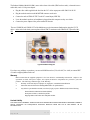
Hall Research Technologies, Inc
3613 W. Mac Arthur Blvd. Suite 612
Santa Ana, CA 92704
Phone:
(714) 641-6607
Fax:
(714) 641-6698
User’s Manual
Model M1-TM Teacher’s Module
Model M1-SM Student’s Module
Computer Training Audio/Video Distribution System
May 17, 2002
Description
Thank you for purchasing the Mirrors-One System. Your system includes a Teacher's Module (Model M1-TM)
equipped with a push-button switch cord, a number of Student Modules (Model M1-SM), and interconnecting
cables.
In addition, 2 terminators (Model TM-75) are also provided, which are used at the end of each daisy-chain.
Please take inventory of all items received and inform the factory if anything is missing.
Installation
(A) Teacher's Station
The Teacher's Module (Model M1-TM), comes with a short video cable (HD15 male-to-male), a short mini-stereo
audio cable, a 12 vdc power adapter, and a push-button control cord.
•
Plug the video cable supplied in the box from the PC's video output port to M1-TM's VIDEO INPUT.
•
Connect the PC's sound output (LINE OUT) to the unit's AUDIO INPUT (normally the Line Out from the
PC would go to a pair of powered speakers)
•
Plug the instructor's Monitor to the VIDEO OUTPUT connector on the unit.
•
Plug the instructor's powered speakers into the AUDIO OUTPUT connector of the unit.
Page
2
of
4
............................
•
Plug the push-button switch cord to the CONTROL plug on the box.
•
Connect the power adapter to the power terminal on the unit.
The two CHAIN outputs of Module can be connected to the Student units using the CVGX cables. If you will be
linking all of the student units on one daisy chain, then plug a terminator (Model TM-75) into the unused connector
of the box and terminate the last Student unit on the daisy chain with a TM-75 (i.e. the two CHAIN outputs are
eventually terminated).
Operation of the Teacher's Module:
With the push button light off (power on default mode), no video or audio distribution is taking place.
To take over all student monitors, press the push button switch once; the LED on the switch illuminates and the
image from the instructor's monitor is being displayed at full resolution and speed on all student monitors. At the
same time whatever sound is being produced at the instructor's station, is also broadcast to all student stations.
To release student monitors, press the button again. The light on the LED shall go out and the system becomes
transparent to the classroom.
To blank student monitors, press the push-button twice (double-click). the LED will blink to indicate that all
monitors are blanked at the moment. Of course, the sound distribution from the instructor's station is still active. To
come out of the blanking mode, press the button again.
Audio Distribution Concerns
If the instructor would like his own voice to be broadcast to all student stations at the same time as video
distribution, he/she can simply plug in a microphone into the instructor computer's Mic input (usually on the sound
card). In Windows operating system you can double click on the speaker icon to access individual slider volume
controls for all sound devices (may need to be activated first in the options menu).
When the sound is being broadcast from the teacher's station, the best signal to noise ratio (S/N) is accomplished
when the output sound level of the instructor's PC is at or near the max level. In this case the sound volume heard at
the teacher's own speakers can be reduced using the volume control on the speaker.
To adjust the sound level at the student stations so that they are about the same loudness, use the LINE INPUT slider
control of the individual PC's (prior to taking over the student monitors with the push-button), and set them at a level
less than half way up. You can then use an iterative procedure to adjust the line input levels of all student monitors to
any desired level.
(B) Student's Station
Page
3
of
4
............................
The Student's Module (Model M1-SM), comes with a short video cable (HD15 male-to-male), a short mini-stereo
audio cable, and a 12 vdc power adapter.
•
Plug the video cable supplied in the box from the PC's video output port to M1-SM's LOCAL IN.
•
Plug the student's monitor to the MONITOR connector on the unit.
•
Connect the unit's AUDIO OUTPUT to the PC's sound input (LINE IN).
•
Leave the student's speakers (or headphones) plugged into their computer as they were before.
•
Connect the power adapter to the power terminal on the unit.
The two CHAIN IN and CHAIN OUT of the Module are used to interconnect Student units using the CVGX
cables. At the end of each chain you must place a Model TM-75 terminator at the CHAIN-OUT port of the M1SM.
Typical Installation Diagram
If you have any problems or questions, you can reach Hall Research at (714) 641-6607, fax -6698, or contact HRT
via email at [email protected].
Warranty
HRT warrants that the supplied equipment is free from defective workmanship and material. Subject to the
agreements set forth, will repair or replace, at its option, the defective components for a period of 2 years after
purchase. The following conditions apply to the Warranty:
•
Warranty void if item subject to improper use, negligence, or unauthorized modification
•
Instructions must be followed in obtaining RMA number as explained below
•
Any defective part should be returned, insured and freight prepaid, to Hall Research, with the following:
Return Material Authorization Number (RMA#)
Description of failure, as detailed as possible
Shipping address and contact name and phone number
Limited Liability
IN NO EVENT SHALL THE DIRECT VENDOR’S LIABLITY EXCEED THE PRICE PAID FOR THE PRODUCT FROM DIRECT, INDIRECT,
SPECIAL INCIDENTAL OR CONSEQUENTIAL DAMANGES RESULTING FROM THE USE OF THE PRODUCT OR ITS
DOCUMENTATION
Page
4
of
4
............................