1
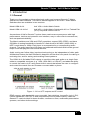
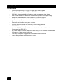
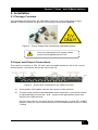
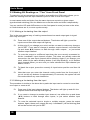
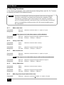
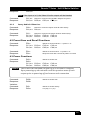
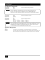
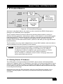
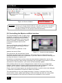
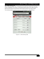
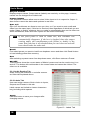
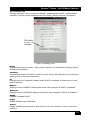
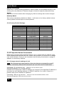
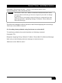
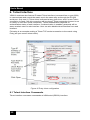
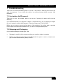
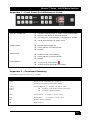
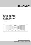
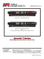
User’s Manual VSM-A-4-4 4x4 VGA + Audio Matrix Switch VSM-I-A-4-JA4 4x4 VGA + Audio Matrix Switch with A/V on Twisted Pair (UTP) outputs & Control over IP Genesis ™ Series 4x4 VGA & Audio Matrix Switches CUSTOMER SUPPORT INFORMATION Order toll-free in the U.S. 800-959-6439 FREE technical support, Call 714-641-6607 or fax 714-641-6698 Address: Hall Research, 1163 Warner Ave. Tustin, CA 92780 Web site: www.hallresearch.com E-mail: [email protected] UMA1197 Rev. N/C Genesis™ Series 4x4 AV Matrix Switches TRADEMARKS USED IN THIS MANUAL Hall Research and its logo are trademarks of Hall Research. Any other trademarks mentioned in this manual are acknowledged as the property of the trademark owners. FEDERAL COMMUNICATIONS COMMISSION RADIO FREQUENCY INTERFERENCE STATEMENT This equipment generates, uses, and can radiate radio frequency energy and if not installed and used properly, that is, in strict accordance with the manufacturer’s instructions, may cause interference to radio communication. It has been designed to comply with the limits for a Class A computing device in accordance with the specifications in Subpart B of Part 15 of FCC rules, which are intended to provide reasonable protection against such interference when the equipment is operated in a commercial environment. Operation of this equipment in a residential area is likely to cause interference, in which case the user at their own expense will be required to take whatever measures may be necessary to correct the interference. Changes or modifications not expressly approved by the party responsible for compliance could void the user’s authority to operate the equipment. 1 User’s Manual Contents 1. Introduction............................................................................................................ 3 1.1 General .................................................................................................................. 3 1.2 Features ................................................................................................................ 4 2. Installation.............................................................................................................. 5 2.1 Package Contents ................................................................................................. 5 2.2 Input and Output Connections ............................................................................... 5 2.3 Connection Block Diagrams .................................................................................. 8 3. Configuration & Operation ................................................................................... 8 3.1 Front-Panel Buttons and Indicators ....................................................................... 8 3.2 Turning the unit on and off..................................................................................... 9 3.3 Making AV Routings or “Ties” from Front Panel .................................................. 10 3.4 Saving Presets (routing patterns) ........................................................................ 11 3.5 Recalling Presets (routing patterns) .................................................................... 11 3.6 Resetting system to factory defaults.................................................................... 11 4. Control Commands (RS-232 and IP) .................................................................. 11 4.1 Routing Functions................................................................................................ 12 4.2 Preset Save and Recall Functions ...................................................................... 13 4.3 Power Functions .................................................................................................. 13 4.4 Special Commands ............................................................................................. 14 4.5 Error Responses.................................................................................................. 14 5. IP Control Basics ................................................................................................. 15 5.1 Getting Device IP Address .................................................................................. 15 5.2 Controlling the Matrix via Web Interface.............................................................. 16 5.3 IP Specific Serial Commands .............................................................................. 20 6. Telnet Interface .................................................................................................... 22 6.1 Telnet Interface Commands ................................................................................ 22 7. Troubleshooting .................................................................................................. 23 7.1 Contacting Hall Research .................................................................................... 23 7.2 Shipping and Packaging ...................................................................................... 23 8. Specifications ...................................................................................................... 24 Appendix 1 – Front Panel Quick Reference Guide ............................................... 25 Appendix 2 – Command Summary ........................................................................ 25 2 Genesis™ Series 4x4 AV Matrix Switches 1. Introduction 1.1 General Thank you for purchasing this professional quality and compact Genesis™ Matrix Switch from Hall Research. This User’s Manual applies to 4x4 VGA + Audio Matrix Switchers that are available in two versions: Model VSM-A-4-4 4x4 VGA + Audio Matrix Switch Model VSM-I-A-4-JA4 4x4 VGA + Audio Matrix Switch with A/V on Twisted Pair (UTP) outputs & Control over IP As members of Hall’s Genesis™ series these matrices are synonymous with high performance, intuitive and powerful user interface, easy to use control command set, and unsurpassed reliability. The Matrix switches are VGA and YPbPr compliant, support DDC (EDID), and have 550 MHz of analog bandwidth to handle PC resolutions to WUXGA (1920x1200) or HDTV resolutions to 1080p. Each input is accompanied by a corresponding audio channel. The audio inputs are L/R stereo on balanced terminals that eliminate ground loops noise that plagues most similar devices. Audio routing can follow video (synchronized routing) or be independent of video path. All Matrices feature the Hall Research’s beautiful and intuitive front panel for making or reviewing ties, and for saving and recalling Preset patterns. The VSM-I-A-4-JA4 adds RJ45 outputs to send the video and audio on a single Catx cable to compatible receivers (e.g. URA, URA-SKU, or URA-XT) and adds the ability to control the matrix via IP using smart built-in server that allows the user to configure and control the matrix from any browser or smart tablet or phone. Figure 1 - AV on UTP outputs and IP control EDID support, wide-bandwidth, zero cross-talk, fast switching, low profile (only 1 RU), Preset capabilities, RS-232, IP and comprehensive front panel controls, make the Genesis™ matrices ideal for home theater, conference room, multimedia presentation systems, and other similar settings. 3 User’s Manual 1.2 Features 4 • Cross-point switching of PC or HD video and audio signals • Supports all Component HDTV and RGB PC resolutions • 550 MHz video bandwidth to for sharp and unsurpassed clear image • Zero cross-talk, so no bleed from unselected inputs on the output image • Supports balanced stereo line-level audio inputs and outputs • Independent or synchronized switching of Audio and Video • Outputs can be blanked • Powerful and intuitive front panel controls • Preset Save and Recall of commonly used routing patterns • DDC/EDID compliant inputs • Includes RS-232 port with Hall Research’s intuitive Genesis Control Command Set (GCCS™) • IP (LAN) version includes http-server with easy to use controls user definable I/O names, Telnet control, and more • 1RU high compact & rugged rack mountable metal enclosure • 100% designed and manufactured in USA Genesis™ Series 4x4 AV Matrix Switches 2. Installation 2.1 Package Contents Your package should contain the 1RU Matrix Switcher, a Universal power supply (Model 511-3A-161WP05, 5v @ 2.6A 2.1mm plug), and a User’s Manual. Figure 2 – Power Supply with international switchable blades Use only regulated 5v DC supply (center positive) as supplied with the unit. 2.2 Input and Output Connections The matrix is housed in a 1RU 19” wide rack mountable enclosure. All of I/O, control, and the power connections are on the rear of the unit. Figure 3 – Rear Panel Connections (for VSM-I-A-4-JA4) Using quality VGA cables connect the inputs to video sources. Connect audio inputs to the detachable screw terminals. If your audio source is balanced then connect the + and – inputs to the appropriate inputs and shield to the GND terminal. On the other hand if your audio input is unbalanced (as on most PC’s or MP3 players), then you can connect the source to the balanced as shown in Table 1 below 5 User’s Manual Easy Connection Note connection is to negative inputs Alternate Connection If connecting to Positive inputs, you must jumper negative inputs to ground or volume will be cut in half Connection to remove ground loop If your source is ground referenced and the output of the matrix is also connected a ground referenced device, and there is noise between the grounds, or you are using long audio cables, then you have a classis situation for picking up 60 cycle and other noise due to ground loop. In this case we recommend this alternate connection where you remove the connection to the ground screw terminal. se this only if you have noise and suspect it is caused by ground loop Table 1 – Unbalanced input connection methods 6 Plug the HD15 video outputs to LCD’s If you have the JA4 output option, then you can use Cat5e/6 UTP cables to connect the outputs to compatible Receivers upto 1000 feet (300m) away. Compatible receivers include URA, URA-SKU, or URA-XT. Note that the Genesis™ Series 4x4 AV Matrix Switches URA does not have RGB Skew correction so you would need to use lowskew UTP cable for that option if the distance is over 200 ft. The URA-SKU, or URA-XT, both have RGB skew correction so you can use any Cat5e or Cat6 cable regardless of length Similar to the audio input, the audio outputs are also balanced. So when connecting to balanced devices use both + and – terminals. But if you are connecting the output to unbalanced sinks (such as using 3.5mm mini-stereo plugs), do not connect the unused outputs to ground. You can connect the tip and ring to either + sides or the – sides, as shown below. Figure 4 – Connecting balanced audio outputs to unbalanced devices If the matrix needs to be controlled via RS-232, plug the controller (or PC) to the DB9 Female port on the rear of the matrix. Connection to PC’s DB9 Male is made using a straight through DB9 Male-to-Female cable (as shown below). DB9-Female on Matrix Pin Function 2 TX (output) 3 RX (input) 5 Ground Controller DB9-Male Pin Function 2 RX (input) 3 TX (output) 5 Ground Table 2 – RS-232 Control Port Pinout Note on RS-232 port availability on PC Most PCs do not have a serial port, so you may need a USB to RS-232 Serial converter. These are available from Hall Research (Model USB-RS232-1). The 4x4 VSM matrix is available with IP port (VSM-I- …). On these units there is an RJ45 (10/100 Base-T) for connection to your Local Area Network. 7 User’s Manual 2.3 Connection Block Diagrams Figure 5 – Connection Block Diagram for VSM-A-4-4 Figure 6 – Connection Block Diagram for VSM-I-A-4-JA4 3. Configuration & Operation 3.1 Front-Panel Buttons and Indicators An image of the front panel for the 4x4 matrix is shown below. Figure 7 – HSM-04-04 front panel controls & indicators 8 Genesis™ Series 4x4 AV Matrix Switches The front panel can be used for the following purposes: • Monitor & Control Power On/Off status • View current Input/output routings (ties) on Routing Status LED Grid on the front panel • Make new ties either starting from input or from output point of view • Use VID and AUD buttons for independent or synchronized routing of audio and video • Recall preset tie patterns • Save preset tie patterns All of the front panel switches have built-in LEDs that help in the operation. Front panel functions are designed for maximum intuitiveness. With just a little practice, one can easily learn to monitor and control the matrix like a pro. Notice At any time, you can check the tie pattern on the front panel LED Grid. However if both the VID and AUD buttons are lit, the Grid only shows positions where an output’s audio & video coincide. If the audio and video routing to a particular output are not synchronized, then the LED position in the Grid will be off. In that case to can examine just the Video ties or just the Audio ties by only having VID or AUD button active Figure 8 – Connection grid on front panel 3.2 Turning the unit on and off To turn the unit on, press the power button. The unit will do a LED test where all buttons and LED’s are turned on for a few seconds. Then the matrix will recall the last routing pattern prior to being shut -down and update the Routing Status LED Grid. To turn the Matrix off, press and hold the power button for 5 seconds. This is done as a precaution, so that if the power button is accidentally touched, it will not turn off the matrix! 9 User’s Manual 3.3 Making AV Routings or “Ties” from Front Panel To make the unit as convenient and intuitive as possible the VSM matrix allows you to make ties starting from the input channel’s point of view or from the output. In most cases audio and video from the same input are routed to a given output (synchronized switching). But the Matrix can route the audio and video independently. You can use the VID and AUD buttons on the front panel to route just one or the other, or if both buttons are lit, to route synchronously. 3.3.1 Making a tie starting from the output This is the most natural way of making connections since each output gets is signal from only one input. Press one of the output channel buttons. That button will light up and the inputs routed from that output will light up. At this point if you change your mind, and do not want to make any changes, just hit SET. If you want to change to another output channel, use either the up and down ▲▼) ( buttons to walk through other outputs ; or just select another output channel. To route the output to a different input than the one currently connected to, hit the “candidate” input channel number. This does not actually make the connection; the new input channel will be blinking. Again if you change your mind, either hit the same blinking button (it will stop blinking), or hit another input channel. When you are sure you have selected the input channel you desire, hit SET. To blank the output, press the currently lit input button position and then hit SET Note that once you enter the channel routing mode from the front panel, if you do not hit any buttons for approximately 10 seconds, the system will exit this mode without any user interaction. 3.3.2 Making a tie starting from the input The procedure is similar to the above but a particular input can be routed to more than one output or none at all! 10 Press one of the input channel buttons. That button will light up and ALL the outputs routed from that input will light up. If you want to change to another input channel, use either the up and down (▲▼) buttons to walk through other inputs; or just select another input channel. To route the selected input to single or multiple outputs, press the output buttons. Again, these new outputs are only “candidates” (will be blinking) and will not be routed until you hit SET. Genesis™ Series 4x4 AV Matrix Switches 3.4 Saving Presets (routing patterns) Current tie configuration (snap-shot of the way video and audio are routed at the moment) can be saved as a PRESET for later recall. The Matrix can memorize 8 PRESETS. Each of the 4 input and 4 output buttons can memorize a preset for a total of 8. To save the current AV routing pattern, press and hold the PRE button for 3 sec, the backlit LED will start flashing (this means that save function is activated). Press the desired input/output button position to save the preset then press the SET button to complete the operation. 3.5 Recalling Presets (routing patterns) Press and release the PRE (preset) button. The button will light up solid. Then press and release one of the channel buttons and hit SET. 3.6 Resetting system to factory defaults Disconnect the power from the unit. Press and hold the POWER button on the front panel while plugging in power. Continue to hold the ENTER button until all LEDs on the front panel flash on. System reset clears all ties and presets. 4. Control Commands (RS-232 and IP) The Genesis™ Matrices can be controlled via an external control system by using either the standard RS-232 or the optional IP port. Any program capable of standard serial communication in ASCII format is capable of working with the matrix. Most PCs with Windows™ OS have HyperTerminal™ or equivalent. There are also many free Terminal Emulator software programs available for download on the internet. Use a DB9 Male-to-Female cable per Table 2 to connect the unit to the PC’s serial port. Use 19,200 Baud, 8 bits, No Parity, 1 Stop bit, No flow control. Upon power up, the Matrix will output a screen similar to the figure below through its serial port. STRING MEANING PW1« Power is on CV1,1« Connect Video output 1, to input 1 CV2,1« Connect Video output 2, to input 1 CV3,1« Connect Video output 3, to input 1 CV4,1« Connect Video output 4, to input 1 CA1,1« Connect Audio output 1, to input 1 CA2,1« Connect Audio output 2, to input 1 CA3,1« Connect Audio output 3, to input 1 CA4,1« Connect Audio output 4, to input 1 11 User’s Manual 4.1 Routing Functions In the following paragraphs, the symbol « represents Carriage Return (Hex 0D). The * character is a wildcard (acts similar to DOS wildcard character) Notice 4.1.1 Almost all commands issued to the Matrix will elicit a response once the command is accepted and execution completed. After issuing any command, you must wait for the matrix’s response prior to sending another command. If you send another command prior to completion of the previous one, the matrix might ignore the command Make video ties: Command: Response: CVn,m« Stands for Connect Video n = output, m= input CVn,m« Note: If the input m is 0, the video output n will be blanked. Command: Response: 4.1.2 CV*,m« Stands for Connect All Video Outputs to input m CV1,m« CV2,m« CV3,m« CV4,m« Query video ties: Command: Response: CVn« CVn« Command: Response: CV*« Stands for Connect All Video Query CV1,m« CV2,m« CV3,m« CV4,m« 4.1.3 Stands for Connect Video n Query Make Audio ties: Command: Response: CAn,m« Stands for Connect Audio n = output, m= input CAn,m« Note: If the input m is 0, the Audio output n will be disconnected/muted. Command: Response: 4.1.4 CA*,m« Stands for Connect All Audio Outputs to input m CA1,m« CA2,m« CA3,m« CA4,m« Query Audio ties: Command: Response: CAn« CAn« Command: Response: CA*« Stands for Connect All Audio Query CA1,m« CA2,m« CA3,m« CA4,m« 4.1.5 Make Synchronized Audio+Video ties: Command: 12 Stands for Connect Audio n Query COn,m« Stands for Connect both A&V n = output, m= input Genesis™ Series 4x4 AV Matrix Switches Response: COn,m« Note: If the input m is 0, the Video & Audio outputs will be blanked Command: Response: 4.1.6 CO*,m« Stands for Connect All both A&V Outputs to input m CO1,m« CO2,m« CO3,m« CO4,m« Query Audio & Video ties: Command: Response: COn« Stands for Connect Output Audio & Video Query CVn,m« CAn,m« Command: Response: CO*« Stands for Connect All Output Audio & Video Query CV1,m« CV2,m« CV3,m« CV4,m« CA1,m« CA2,m« CA3,m« CA4,m« 4.2 Preset Save and Recall Functions Command: Response: PRx« Stands for Preset Recall. x = preset 1~ 8 CV1,m« CV2,m« CV3,m« CV4,m« CA1,m« CA2,m« CA3,m« CA4,m« Command: Response: PSx« PSx« Stands for Preset Save. x = preset 1~ 8 Response sent after current tie pattern is saved 4.3 Power Functions Command: Response: Notice PW1« Stands for Power On PW1« CV1,m« CV2,m« CV3,m« CV4,m« CA1,m« CA2,m« CA3,m« CA4,m« The Power ON Command can take up to 5 seconds to complete. Upon powering up the unit will recall the previous state of each output prior to powering off and restore each connection Command: Response: PW0« PW0« Stands for Power Off Variation: Command: Response: PW« PWx« Stands for Power Query x=0 (off), or 1 (on) 13 User’s Manual 4.4 Special Commands Command: Response: Notice FD« FD« Stands for Recall Factory Defaults Factory Default command will clear all audio/video ties and presets. The units with IP interface have a slightly different response to this command. Please see section 5.3 for further details Command: Response: FW« FWx.y« Command: Response: ST« Stands for Status request PW1« CV1,m« CV2,m« CV3,m« CV4,m« CA1,m« CA2,m« CA3,m« CA4,m« Notice Stands for Firmware Version The 4x4 VSM matrices equipped with IP Port have additional Serial Commands to change IP address parameters. Please refer section 5.3 IP Specific Serial Commands for further info 4.5 Error Responses ERR1« ERR2« 14 Command is not recognized, has invalid parameter or wrong syntax The only valid command while power is off is Power Status query (PW«), all other commands issued while power is off will result in this error message Genesis™ Series 4x4 AV Matrix Switches 5. IP Control Basics Figure 9 – IP Control Block Diagram As shown in the figure above, the matrix can be controlled via RS232 Serial port or through an IP (Ethernet) port if equipped. The IP interface features a built-in web server allowing web browsers running on different devices (computer, smart-phone, tablet) on the network to control and monitor matrix through HTTP protocol on port 80. (Section 5 will walk you through this HTTP based Web Interface). The IP interface also supports telnet connection over port number 6324 to control and monitor matrix. (Section 6 will walk you through this telnetbased interface) The IP interface on every matrix shipped has a unique MAC-address, and must have a valid IP-address to function properly on the network. Notice As shipped from factory DHCP is enabled. This means that the network automatically assigns an IP address to your Matrix. To find the IP address assigned to the matrix, please use Device Installer Software to get current IP address of Matrix. Device Installer is available on the Product’s webpage download tab at www.hallresearch.com 5.1 Getting Device IP Address The VSM matrix comes preconfigured for DHCP, which means it will automatically obtain an IP address when it is connected to the LAN. It is recommended that you set a static IP on each system in order to guarantee it maintains the same address. In order to set a static IP you must first discover what DHCP address was issued and then login to reconfigure the settings. Download and install the DeviceInstaller utility from Hall Research website. Once installed, run the program. It will scan your LAN and locate any devices that are connected. 15 User’s Manual Figure 10- Device Installer Notice Device IP Address Don’t try to change the IP address using this utility! The IP address can be changed from Web interface (section 5.2) or from Serial interface (section 5.3 IP specific Serial Commands) 5.2 Controlling the Matrix via Web Interface The Genesis Matrices with IP option have a powerful, yet easy to use IP based web interface to control and monitor matrix. Web browser application running on any device (Computer, Smartphone, iPad™) on the same network can use this interface. Once you have the correct IP address of your device, open web browser of your choice and type http://your.device.ip.address in the address bar and hit Enter. Figure 11 – Control via web Interface The web server will automatically format the display for the browser it is running on. This means that on a Smart Phone the width and character sizes will be optimized so you don’t have to deal with zooming and scrolling the screen to use the unit. Furthermore, all elements on the screen are automatically updated from server side. This means that if the video routing is altered by the front panel of the matrix or another simultaneous LAN connection, your screen will automatically update. Web interface allows the user to change/monitor matrix I/O ties, sync audio/video together, assign names to Inputs, outputs and presets as well as change IP address, assign static IP address, enable/disable password protected login etc… Preset, Input and Output names are saved permanently in matrix unless user changes it. Matrix also remembers Presets even when not powered. The web interface is very user friendly and easy to access. It consists of four tabs named Video, Audio, Labels and Settings. Video and Audio are tabs for routing video and audio separately. Each tab and its features are explained in next sections. 16 Genesis™ Series 4x4 AV Matrix Switches 5.2.1 Video Routing Tab Video routing tab allows user to change the input channel for each output, save the current configuration as a preset, load existing presets and turn the matrix On/Off. It also has sync feature to synchronize audio & video routing on any given output The following depicts a typical screen as it would appear on a Smart-Phone. Figure 12 - Video Routing Tab 17 User’s Manual Outputs Column Displays output names. Output names (labels) are read-only on this page, however; names can be changed from Labels tab. Inputs Column Four dropdown buttons allow user to select Video Input to tie to respective Output. It also shows current ties status and updates in real time. Sync A/V Sync A/V checkboxes are there to save you time, so if you want to route audio and video from the same input, if this box is checked, then regardless of which tab you are under (Video or Audio), whatever ties you make is automatically done on the other one. When unchecked, audio and video inputs can be routed individually. Note: If the front panel is used to make ties, this checkbox can automatically disappear. If the box is checked, then the output routing under the complimentary tab (Video or Audio) is the same. But if the box is not checked then you can’t be sure and will have check under the other tab . Recall First select preset you want to load from dropdown menu and then click Recall button to load existing preset from memory. Save After selecting a preset name from dropdown menu, click Save state as a Preset ON/OFF These buttons show the current status of Matrix’s power and can be used to turn it on and off. The button with red boarder is the current state and cannot be clicked. The other one is available. 5.2.1 Audio Routing Tab Audio routing tab functions in a similar manner as Video tab explained above 5.2.2 Labels Tab User can assign names of their choice to Inputs, Outputs and Presets in this tab. Label names are limited to sixteen characters long including white spaces. Apply Click this button to save your changes after changing names. Figure 13 - Labels Tab 18 Genesis™ Series 4x4 AV Matrix Switches 5.2.3 Settings Tab Settings tab helps user to change IP address, enable/disable DHCP, enable/disable password, change current password and load factory default settings if necessary. Figure-14 Settings Tab Name User defined name for matrix. Name can be sixteen (16) characters including spaces and special characters. Location User defined location of matrix. Location can be twenty (20) characters long including white spaces and special characters. IP Displays current IP address of Matrix and if DHCP is disabled, it allows user to enter new IP address. Subnet Displays current SUBNET address and allows user change it If DHCP is disabled. Gateway Displays current GATEWAY address and allows user change it if DHCP is disabled. DHCP Enables/ Disables DHCP. Login Enable /Disable login password. Telnet Enable /Disable telnet interface. See Section 6 for more details on how to use telnet interface. 19 User’s Manual Change Password? Allow user to change existing password. When clicked, a new window will pop up for entering the new password. Password length is limited to eight (8) characters long. Apply User must click this button after changing any field on settings tab to save changes. Factory Reset This button loads factory defaults to Matrix. It will reset unit to factory default values. Factory default will also wipe out saved presets. 5.2.4 Factory Default Settings Field Name in GUI Power VIDEO INPUT n AUDIO INPUT n VIDEO OUTPUT n AUDIO OUTPUT n PRESET n Name Location IP Subnet Gateway DHCP Login Telnet Default Password Default Value Off Vid_In_n Aud_In_n Vid_Out_n Aud_Out_n PRESET_n VSM Matrix Hall Research Assigned by DHCP Based on IP Assigned by DHCP Enabled Disabled Disabled Pass Tab in GUI Video Labels Labels Labels Labels Labels Settings Settings Settings Settings Settings Settings Settings Settings Settings 5.3 IP Specific Serial Commands HSM matrix equipped with IP interface allows user to assign Static IP address using Serial Interface with standard RS-232. Please refer section 4 to connect PC to Matrix over serial interface. Once you are connected use following Commands to assign IP address or load factory defaults. 5.3.1 Change network settings of unit Note: All commands are case sensitive. Also note that you must specify a new IP address, followed by SB and GE commands (all 3) for the new IP to take effect Command: IP xxx.xxx.xxx.xxx« stands for new IP address value. Success Response: IP= xxx.xxx.xxx.xxx« Possible error Responses: ERR! IP address not changed (if the specified IP address is the same as unit’s existing address), or ERR! IP address is not valid. If there is a problem with new IP address as specified Command: SB xxx.xxx.xxx.xxx« stands for new Subnet Mask address value. Success Response: SB= xxx.xxx.xxx.xxx« 20 Genesis™ Series 4x4 AV Matrix Switches Command: GW xxx.xxx.xxx.xxx« stands for new Gateway address value. Success Response: GW= xxx.xxx.xxx.xxx« Notice User MUST enter ALL THREE Commands mentioned above with correct values and must get ‘success response’ for each to change IP address. Once you have successfully entered all above commands the unit will respond with: “Applying Settings To Matrix- Please Wait for Welcome Message” The Welcome message confirms that device has finished applying the new settings “Welcome to the VSM-I-A matrix” 5.3.2 Loading factory defaults using Serial port on units with IP To load factory defaults from serial interface use following command. Command: FD« Response: Applying Factory Defaults To Matrix- Please Wait For Welcome Message. Wait until you see following welcome message on terminal screen. “Welcome to the VSM-I-A matrix” 21 User’s Manual 6. Telnet Interface VSM-I-A matrices also feature IP based Telnet interface (command line on port 6324) to communicate and control the matrix much the same way as through the RS-232 serial port. Only one (1) Telnet client is allowed at any given time, and if a new Telnet connection is made, the old connection will be closed. Telnet connection timeout is set to infinity or until user closes connection. Telnet authentication depends on authentication status of web interface. If authentication is enabled, password will be same as what used for web interface. User can also disable telnet interface from web interface. Following is an example making a Telnet TCP socket connection to the matrix using Putty (an open source telnet client). Figure-15 Putty client configuration 6.1 Telnet Interface Commands Telnet interface uses same commands as VSM serial (RS232) interface. 22 Genesis™ Series 4x4 AV Matrix Switches 7. Troubleshooting There are no field serviceable parts or circuits in the device. Opening the device will void the warranty. If you think the device is malfunctioning, please contact Hall Research. 7.1 Contacting Hall Research There are no user serviceable parts in the device. Opening the device will void the warranty. If you determine that your Genesis™ Matrix is malfunctioning, do not attempt to repair the unit; instead, contact Hall Research Technical Support at 714-641-6607. Before you do, make a record of the history of the problem. We will be able to provide more efficient and accurate assistance if you have a complete description. 7.2 Shipping and Packaging If you need to transport or ship your unit: • Package it carefully. We recommend that you use the original container. • Before you ship the units back to Hall Research for repair or return, contact us to get a Return Authorization (RMA) number. 23 User’s Manual 8. Specifications Video Standards Signal type Connectors Video Bandwidth Video Levels VGA Cable Length RJ45 AV Cable length PC Resolutions VGA thru WUXGA, and 480i through 1080p RGBHV or YPbPr HD15 550 MHz -0.3v to 0.7v (1 V p-p) on RGB, 0 to 5v DC on Sync 150 ft max. 1,000 ft max (when used with appropriate AV over UTP Receiver VGA through UXGA Audio Input signal type Output signal type Level Bandwidth General Power Supply Nominal Power Temperature/humidity Cooling Mounting Enclosure type Dimensions Product weight Shipping weight Recommended cable Vibration Safety EMI/EMC MTBF Warranty Balanced Stereo Balanced Stereo 0 to +4dBu (0.78 to 1.23Vrms) line level 20 Hz to 20,000 Hz 100 VAC to 240 VAC, 50-60 Hz, external; 5 VDC, 2.6 A, regulated Fully loaded, 10 watts max Storage: -40 to +158 °F (-40 to +70 °C) / 10% to 90%, non-condensing Operating: +32 to +104 °F (0 to +40 °C) / 10% to 90%, non-condensing Convection Front panel 1RU 19” Rack mountable Metal 1.65" H x 17" W x 5.5" D (42 mm H x 432 mm W x 140 mm D) F/P: 1.7” H x 19” W (43 mm H x 483 mm W) 9 lb (4 kg) 10 lb (4.5 kg) Hall Research Ultra-Thin multicoax VGA cable ISTA 1A in carton (International Safe Transit Association) CE CE, FCC Class A 90,000 hours 2 years parts and labor Specifications are subject to change without notice 24 Genesis™ Series 4x4 AV Matrix Switches Appendix 1 – Front Panel Quick Reference Guide Figure 16 – Control buttons on the front panel Function Procedure View ties or Make ties Hit VID or AUD for Video or Audio, or both (button lights) Hit PRE (button lights up) Hold PRE until it starts blinking To turn on hit power button Recall Presets Save Presets Power ON/OFF Hit any of the INPUT or OUTPUT Buttons To change ties, hit any INPUT or OUTPUT then hit SET Use ▲ and ▼ buttons to quickly scroll Hit any INPUT or OUTPUT button Hit SET Hit any INPUT or OUTPUT button Hit SET To turn off Press and hold power button Appendix 2 – Command Summary (Commands require carriage return - Hex 0D) Command Function PWx Power on/off x=0 power off, 1 power on Omitting x will show current power status CVn,m CAn,m COn,m Connect Output n = output (* for all), m= input Omitting ,m will show current connections V=Video, A=Audio, O=Both PRx Preset Recall... x = preset # can be 1 to 8 PSx Preset Save FD Restore Factory Defaults ST Status Report ... x = preset # can be 1 to 8 25 User’s Manual 26 Genesis™ Series 4x4 AV Matrix Switches 27 User’s Manual 28 © Copyright 2012. Hall Research, Inc. All rights reserved. CUSTOMER SUPPORT INFORMATION Order toll-free in the U.S. 800-959-6439 FREE technical support, Call 714-641-6607 or fax 714-641-6698 Mail order: Hall Research, 1163 Warner Ave. Tustin, CA 92780 Web site: www.hallresearch.com E-mail: [email protected]