1
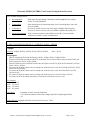
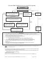
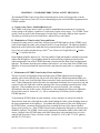
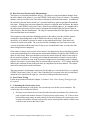
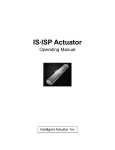
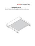
Visual Acuity Testing Procedures Manual Version 1.4 Revised October 2013 RVACC Visual Acuity Testing Procedures Manual_2013-10-17.docx Table of Contents CHAPTER 1: VISUAL ACUITY TESTING USING THE EVA SYSTEM ............................... 3 A. Electronic Visual Acuity Tester .......................................................................................... 3 1. EVA System Description – Current Models ................................................................... 3 2. EVA System Description – Legacy Models ................................................................... 4 3. System Calibration .......................................................................................................... 4 B. E-ETDRS Testing Protocol................................................................................................. 5 1. Overview of E-ETDRS Visual Acuity Testing Protocol ................................................ 5 2. Visual Acuity Testing Procedures .................................................................................. 8 3. Safeguards to Avoid Bias................................................................................................ 9 C. Poor Vision Testing (Testing Light Perception) ................................................................. 9 CHAPTER 2: STANDARD ETDRS VISUAL ACUITY PROTOCOL .................................... 10 A. Visual Acuity Chart: Modified Bailey-Lovie .................................................................. 10 B. Illumination of Visual Acuity Charts and Room .............................................................. 10 C. Maintenance of ETDRS Visual Acuity Charts and Room................................................ 10 D. Best-Corrected Visual Acuity Measurements ................................................................... 11 E. Poor Vision Testing .......................................................................................................... 11 F. Calculating the Visual Acuity Score ................................................................................. 11 RVACC Visual Acuity Testing Procedures Manual_2013-10-17.docx Page 2 of 12 CHAPTER 1: VISUAL ACUITY TESTING USING THE EVA SYSTEM It is essential to have standardized visual acuity measurements for each examination at each of the participating clinics to minimize the effects of acuity examiner and subject bias. Visual acuity testing is performed with the Electronic Visual Acuity Tester (EVA) using a protocol called the Electronic ETDRS (E-ETDRS) Visual Acuity Testing Protocol. This protocol has been developed to provide a visual acuity score that is comparable to that using the manual testing protocol used in the Early Treatment Diabetic Retinopathy Study (ETDRS). The ETDRS chart testing is used as a back-up in case the EVA is not functioning if your site has ETDRS equipment and is ETDRS certified. Visual acuity measurements for each eye are obtained by a certified visual acuity examiner after refraction and before the subject's pupils have been dilated. A. Electronic Visual Acuity Tester 1. EVA System Description – Current Models The most recent EVA (Figure 1) systems use an Apple iPod Touch that communicates with a personal computer running a Windows 7 operating system. For normal (high contrast) testing, stimuli are high-contrast, black letters with luminance of at least 95 candelas/meter2 and contrast of 98%. The system can present single letters or lines of letters. Single letter testing is used in the Electronic ETDRS program whereas lines of letters can be used for refraction. Single letters are framed with crowding bars spaced one letter-width around the letter. For low contrast testing (only on Model 12-WIN EVA Testers), stimuli are gray letters with a contrast of either 2.5% or 5% compared to the white background. Letters are framed with crowding bars of the same contrast. For lines of letters, up to five letters are displayed with a decreasing number of letters per line as letter size increases. With a highresolution (1920x1080) 21.5- or 23.6-inch monitor, the system is capable of displaying letters from 20/800 (1.6 logMAR) to 20/6 (-0.5 logMAR) at a test distance of 3 meters. Letter size is a close, but not exact, approximation of the logMAR progression of the ETDRS charts (within about 2% of the letter size at each logMAR level). The Apple iPod Touch (Figure 2), communicating with the EVA PC via Wi-Fi, provides instructions for the technician, allows entry of identification data, displays the letter that is being shown on the monitor, records the responses, and sends instructions to the EVA PC with regard to the sequence of letter presentations. The size of each letter presentation is determined by a computer program based on the subject’s responses. Figure 1 RVACC Visual Acuity Testing Procedures Manual_2013-10-17.docx Figure 2 Page 3 of 12 2. EVA System Description – Legacy Models The EVA (Figure 3) utilizes a programmed Palm handheld device that communicates with a personal computer running a Linux (or Windows XP) operating system. Stimuli are high-contrast, black-and-white letters with luminance of 85 to 105 candelas/meter2 and contrast of 98%. The system can present single letters or lines of letters. Single letter testing is used in the Electronic ETDRS program whereas lines of letters can be used for refraction. Single letters are framed with crowding bars spaced one letter-width around the letter. For lines of letters, five letters are displayed for sizes smaller than 20/160 on models prior to July 2008 and smaller than 20/200 after July 2008; a decreasing number of letters is displayed as letter size increases. With a high-resolution (1600x1200) 17-inch monitor, the system is capable of displaying letters from 20/800 (1.6 logMAR) to 20/12.5 (-0.2 logMAR) at a test distance of 3 meters. With a 19” LCD monitor at 1280x800 (models since July 2007) the system displays a range from 20/800 (1.6 logMAR) to 20/10 (-0.3 logMAR) at a test distance of 3 meters. Letter size is a close, but not exact, approximation of the logMAR progression of the ETDRS charts (within about 2% of the letter size at each logMAR level). The Palm handheld device (Figure 4), communicating with the EVA through a connected cable or wirelessly with Bluetooth, provides instructions for the technician, allows entry of identification data, displays the letter that is being shown on the monitor, records the responses, and sends instructions to the EVA with regard to the sequence of letter presentations. The size of each letter presentation is determined by a computer program based on the subject’s responses. Figure 3 Figure 4 3. System Calibration Two system calibrations are performed at regular intervals: (1) size calibration to confirm letters are displayed accurately and (2) luminance calibration to confirm the monitor screen is sufficiently bright for testing. Size calibration must be performed at each study visit. For non-study use, size calibration is recommended at least quarterly. Luminance calibration must be performed at each study visit. Refer to the EVA User’s Manual for instructions specific to your EVA Model, monitor and RVACC Visual Acuity Testing Procedures Manual_2013-10-17.docx Page 4 of 12 light meter. EVA User’s Manuals can be found on the EVA website (http://eva.jaeb.org) and find your model under the Documents tab. B. E-ETDRS Testing Protocol The EVA runs a visual acuity testing program called E-ETDRS (which stands for Electronic Early Treatment Diabetic Retinopathy Study). The program has been developed to provide a visual acuity letter score that is comparable to the ETDRS chart testing score. As part of the development of the E-ETDRS protocol, a study was conducted in which high validity and test-retest reliability were demonstrated (Moke PS, Turpin AH, Beck RW et al. A computerized method of visual acuity testing: Adaptation of the amblyopia treatment study visual acuity testing protocol. Am J Ophthalmol 2001; 132:903-14). 1. Overview of E-ETDRS Visual Acuity Testing Protocol In brief, the E-ETDRS Visual Acuity Testing Protocol consists of an initial screening phase to obtain an approximation of the visual acuity threshold and then a testing phase to obtain the visual acuity score. The protocol is summarized below. The complete algorithm is depicted in the figure that follows. RVACC Visual Acuity Testing Procedures Manual_2013-10-17.docx Page 5 of 12 Electronic ETDRS (E-ETDRS) Visual Acuity Testing Protocol Overview The E-ETDRS testing protocol: Screening phase: Testing phase: Test progress: Acuity determination: With single letter presentations, determines smallest logMAR level at which a letter is correctly identified. Starts testing letters by intermixing letter sizes of screening phase score and one level smaller. If a letter is missed at a level, one level larger is added to the testing mix; if a letter is correct at a level, one level smaller is added to the testing mix. Tests 5 letters at each level until smallest level with 5/5 correct and the smallest level with 0/5 correct are determined. IN THE FOLLOWING EXAMPLE, C = CORRECT AND M = MISSED Example: Screening: 20/400c, 20/200c, 20/100c, 20/50c, 20/25m, 20/40m Score = 20/50 Test progress 1. Start by intermixing 20/50 and 20/40 letters: 20/50c, 20/40m, 20/50c, 20/40m, 20/50m 2. Because a 20/50 letter was missed, add 20/63 to the letter mix (so now will have letters of 20/40, 20/50, and 20/63 intermixed): 20/63c, 20/50c, 20/40c 3. Because 20/40 was correct, add 20/32 to the letter mix (mix is now 20/32, 20/40, 20/50, and 20/63): 20/32m, 20/63c, 20/63c, 20/50m 4. Five letters at 20/50 have been tested, so it drops out of the mix (mix is now 20/32, 20/40, and 20/63): 20/63c, 20/40c, 20/32m, 20/40m 5. Five letters at 20/40 have been tested, so it drops out of the mix (mix is now 20/32 and 20/63): 20/32m, 20/32m, 20/63c 6. Five letters at 20/63 have been tested, so it drops out of the mix (mix is now 20/32 only): 20/32m 7. Five letters at 20/32 have been tested; there are no letters left in the mix so test is over Test summary 20/63 5/5 correct 20/50 3/5 correct 20/40 2/5 correct 20/32 0/5 correct Letter Score: 10 (number of letters correctly identified) + 55 (5 times the number of lines above (larger than) 20/63 and through 20/800) = 65 Snellen Notation (logMAR to Snellen conversion for 65 letters): 20/50 RVACC Visual Acuity Testing Procedures Manual_2013-10-17.docx Page 6 of 12 Electronic ETDRS (E-ETDRS) Visual Acuity Testing Protocol Algorithm Screening Phase In each step, one letter is shown at each logMAR level. Show 20/400 letter Incorrect Correct Show letters in 3-level steps (e.g., 20/200, 20/12 20/100, 20/50, 20/25, 20/12) until either a Correct miss or 20/12 correct 20/400 Correct Show letter at each successively smaller level until either a miss or 20/400 correct Correct Show a 20/800 letter Letter missed Show letter 2 levels up from missed level (i.e., level smaller than last correct level) Incorrect Show letter at each successive larger level until correct response or 20/800 is shown Correct Incorrect Letter Missed Show letter at each successively smaller level until a miss or 20/12 correct Screening score is 20/800 Screening score is last correct level or 20/800 if last letter shown is 20/800 1. 2. 3. 4. 5. 6. Threshold Phase To start, the letter pool consists of letters from 2 levels*: the level of screening phase score and one level smaller. Each letter presentation is randomly selected from the active pool of letters with the stipulation that the first letter and every third letter must be from the largest level in active letter pool. A level remains in the active pool until 5 letters are tested at the level. A new level is added to the active letter pool when: a. A letter from largest level in the pool is missed: one level larger is added to letter pool† b. A letter from smallest level in the pool is correct: one level smaller is added to letter pool‡ Testing continues until an upper logMAR level with 5 of 5 letters correct and a lower logMAR level with 0 of 5 letters correct are determined and 5 letters are tested on all levels in between upper and lower logMAR levels.§ Visual acuity score is the number of letters correctly identified during threshold testing, plus 5 letters for each logMAR line above the upper logMAR level through 20/800. NOTE: EVA Models released after July 2008 (6-WRH and above) include a 20/10 letter size. The smallest size on models prior to July 2008 is 20/12. The screening phase uses the letters V, R, K and D. The threshold phase uses the same 5 letters from the Sloan letter set that appear on the original ETDRS charts for right and left eyes. *Unless screening score was 20/12, in which case letter pool consists of only 20/12 level letters (Models with 20/10 include both 20/12 and 20/10 in letter pool) †Unless 20/800 letter is missed. ‡Unless 20/12 is correct (20/10 on newer models.). §If 20/12 (20/10 on newer models) becomes part of the active letter pool, it will be the lower logMAR level. RVACC Visual Acuity Testing Procedures Manual_2013-10-17.docx Page 7 of 12 Testing Procedures Using the EVA Before each subject study visit: Calibrate monitor for letter size Check monitor luminance Check room lighting level (dim incandescent lighting is recommended; fluorescent lighting should not be used; no glare on screen; no spotlights) Before Every Test Verify testing distance from EVA to the front of the patient’s face is 3 meters (118 inches) Turn on Apple iPod Touch OR Palm and remove stylus Study Subject Testing On main menu, tap [E-ETDRS] icon Follow instructions on Apple iPod Touch or Palm Shut Down System ● Turn off the PC tester by selecting [Shutdown] icon on main menu OR Briefly press and release the power button on the EVA tower. 2. Visual Acuity Testing Procedures a. Trial frames are to be used for refractive correction. In addition to the occluder in the trial frame, for testing the right eye, left eye is occluded with an eye patch or pad placed beneath the trial frames and vice versa. b. If the protocol specifies that both eyes are to be tested, the right eye is always tested first. c. Visual acuity testing is to be done without cycloplegia and without pupil dilation. RVACC Visual Acuity Testing Procedures Manual_2013-10-17.docx Page 8 of 12 3. Safeguards to Avoid Bias The examiner will be masked to prior visual acuity scores when feasible for a study. Due to the automated nature of the computerized EVA testing, the potential for induction of bias on the part of the technician is minimized. Technician instructions to the subject are to be minimal: a. The subject should be told that there are only letters and no numbers and that each letter is “bracketed” by lines on all four sides. b. For subjects with poor central vision, it may be suggested that the subject fixate eccentrically or turn or move his/her head from side to side or up and down if this improves visual acuity. If the subject employs these maneuvers, care must be taken to ensure that the fellow eye remains covered. c. When the subject cannot read a letter, he/she is told to guess. If the subject states that a letter is one of two letters, then he/she is asked to choose only one letter and, if necessary, to guess. d. When the subject gives one response but then gives a second response before the first response has been finalized (i.e., before the technician has verified the response as correct or incorrect and before the letter presentation on the EVA screen changes), the subject should be asked if that is his/her final answer; if the subject equivocates, ask the subject to choose one letter. Once the technician has verified the response and the letter presentation has changed on the EVA, no changes can be made in the subject’s response. e. If the subject provides a number or any other response other than one of the 26 letters of the alphabet, the subject should be told again that there are only letters on the chart and to respond with a letter. C. Poor Vision Testing (Testing Light Perception) If the subject cannot identify any letters on visual acuity testing of an eye (i.e., letter score = 0), the eye is tested for light perception with the indirect ophthalmoscope as the light source. The following procedure is required: Room lighting should remain at the level of normal visual acuity testing (dim, incandescent lighting). The trial frame should be removed, and the subject should close the opposite eye and occlude it by making a tight seal with the palm around the orbit and the bridge of the nose. The indirect ophthalmoscope light should be in focus at three feet, and the rheostat set at six volts. From a distance of three feet the beam should be directed in and out of the eye at least four times; the subject should be asked to respond when he/she sees the light. If the examiner is convinced that the subject perceives the light, vision should be recorded as light perception, otherwise as no light perception. RVACC Visual Acuity Testing Procedures Manual_2013-10-17.docx Page 9 of 12 CHAPTER 2: STANDARD ETDRS VISUAL ACUITY PROTOCOL The Standard ETDRS Visual Acuity Protocol should only be used as a back-up in the event the Electronic Visual Acuity Tester (EVA) is not functioning (if your site has ETDRS equipment and is ETDRS certified). A. Visual Acuity Chart: Modified Bailey-Lovie The ETDRS visual acuity charts 1 and 2 are used for standardized measurement of visual acuity. Acuity testing of all subjects, regardless of visual acuity, begins at four meters. Two ETDRS Visual Acuity Charts are used for the measurement of visual acuity, each with a different letter sequence. The right eye will always be tested with Chart 1 and the left eye with Chart 2. B. Illumination of Visual Acuity Charts and Room If required by study protocol, each clinic will have/use an ETDRS light box for the ETDRS visual acuity charts during any study acuity testing if the EVA is non-functional. The light box should be hung on the wall or placed on a stand (that can be purchased from the Lighthouse for the Blind in New York) at a height such that the top of the 3rd row of letters (0.8 LogMAR) is 49 + 2 inches (124.5 + 5.1 cm) from the floor. Room lighting should be between 50 – 100 foot-candles of light and should be uniform between the subject and the light box. Room lighting should be measured using a light meter placed on the white background of one of the ETDRS charts that is inserted into the front of the non-illuminated light box. The distance from the outer canthus of the subject’s eye to the front of the ETDRS chart should be 4.0 meters and should be measured with a tape measure, tautly held, or a rigid measuring stick. C. Maintenance of ETDRS Visual Acuity Charts and Room The two 20-watt (Cool Daylight) fluorescent tubes in the ETDRS light box must be changed annually, and a sticker affixed to the side or back of the light box with the date that the bulbs were changed. Twenty watt (Cool Daylight) fluorescent tubes can be purchased from a local hardware store. When changing the fluorescent tubes, the aluminum fenestrated sleeves must be saved and centered on the new light tubes with the opening of the sleeves pointing towards the back of the light box. If the aluminum sleeves are discarded, they must be replaced. (See ordering information at the end of this section.) Furthermore, when changing the fluorescent light tubes, the new tubes must be “burned in” (i.e., left on continuously for 96 hours) before using the ETDRS light box. To maintain the ETDRS charts in good condition, vision examiners are advised to slide the charts into the front slot of the light box, rather than bending the charts, when changing charts in the front compartment of the light box. To maintain the high contrast of the white background the ETDRS charts, examiners should refrain from touching the front of the charts with their fingers, pens, pencils, etc. If the ETDRS charts become permanently damaged or yellowed, they should be replaced. The ETDRS vision testing equipment (illuminator cabinet, floor stand with casters, Original Series ETDRS charts, and replacement tubes with aluminum sleeves) can be ordered from Precision Vision, 944 First Avenue, La Salle, IL, 61301, 800-772-9211 (phone), and 800-223-2224 (fax). RVACC Visual Acuity Testing Procedures Manual_2013-10-17.docx Page 10 of 12 D. Best-Corrected Visual Acuity Measurements The right eye is tested first and then the left eye. The subject is seated such that the distance from the outer canthus of the subject’s eye to the ETDRS Visual Acuity Chart is 4.0 meters. This testing distance is always used first even if the subject could not be refracted at four meters. In addition to the occluder in the trial frame, the left eye is occluded with an eye patch or pad placed beneath the trial frame. With the lens correction obtained by subjective refraction in the trial frame, the subject is asked to read ETDRS Visual Acuity Chart 1 from the top with the right eye. It is emphasized to the subject that each answer will be scored so adequate time should be allowed for each letter in order to achieve the best identification. The subject is instructed that all of the figures to be read are letters and that there are no numbers. The examiner records each letter identified correctly by the subject as he/she reads the chart by circling the corresponding letter on the ETDRS score sheet (or study form). Letters read incorrectly, or for which no guesses are made, are not marked on this form. Each letter read correctly is scored as one point. The score for each line (including zero if no letters were read correctly on that line) and the total score for the eye are recorded on the form, as soon as the four meter testing has been completed. If the number of letters read correctly at four meters is less than twenty, the test should be repeated at one meter and both the four-meter and one-meter totals should be recorded on the ETDRS score sheet (or study form). Both eyes should be tested at four meters before the subject is moved up to the one-meter test distance. It is strongly advised that the total number of letters correctly read at four meters be calculated as soon as the four meter testing has been concluded in order to identify subjects who require 1 meter testing. Prior to actual testing at one-meter, + 0.75 D sphere should be added to the correction already in the trial frame to compensate for the new distance. The subject must sit for testing at the one-meter distance. The same procedure for obtaining visual acuity for the right eye is used for the left eye, except that ETDRS Visual Acuity Chart 2 is used. Chart 1 should never be exposed to the left eye and chart 2 should never be exposed to the right eye, even when switching charts and occlusion. E. Poor Vision Testing Follow the procedures described in Chapter 1, Section C. Poor Vision Testing (Testing for Light Perception). F. Calculating the Visual Acuity Score After each measurement of visual acuity, the visual acuity score for the visit is calculated. The visual acuity score is defined as follows: If twenty or more letters are read correctly at the four-meter test distance, the visual acuity score is equal to the number of letters (N) read correctly at four meters +30. If one or more but less than twenty letters are read correctly at four-meter distance, the visual acuity score is equal to the number of letters read correctly at four meters plus the number of letters read correctly at one meter in the first six lines. RVACC Visual Acuity Testing Procedures Manual_2013-10-17.docx Page 11 of 12 If no letters are read correctly at either the four-meter distance or the one-meter distance, the visual acuity score is 0, and testing for light perception should be performed as described in Chapter 1, Section C. Poor Vision Testing (Testing for Light Perception). RVACC Visual Acuity Testing Procedures Manual_2013-10-17.docx Page 12 of 12