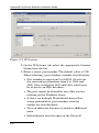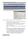
1
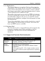
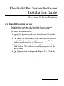
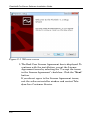
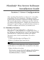
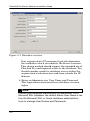
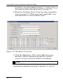
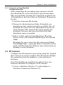
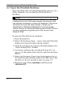
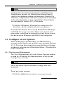
Flowlink® Pro Server Software Installation Guide Part #69-2543-274 ii Flowlink® Pro Server Installation Guide COPYRIGHT © 2006, 2014 Teledyne Isco, Inc. 4700 Superior St., Lincoln, Nebraska, U.S.A. 68504 Phone: (402) 464-0231 Toll Free: (800) 228-4373 FAX: (402) 465-3022 Revision E, November 7, 2014 Part #69-2543-274 iii Flowlink® Pro Server Installation Guide Isco® and Flowlink® are registered trademarks of Teledyne Isco, Inc. Microsoft® and Windows® are registered trademarks of Microsoft Corporation. Oracle® is a registered trademark of Oracle International Corporation All other brand or product names are trademarks or registered trademarks of their respective holders. iv Flowlink® Pro Server Software Installation Guide Table of Contents 1. Introduction 1.1 Product Overview . . . . . . . . . . . . . . . . . . . . . . . . 1.1.1 Database Connection . . . . . . . . . . . . . . . . 1.1.2 IP Listener . . . . . . . . . . . . . . . . . . . . . . . . 1.1.3 Modem Listener . . . . . . . . . . . . . . . . . . . . 1.1.4 Alarms Server . . . . . . . . . . . . . . . . . . . . . . 1.1.5 Database Tool . . . . . . . . . . . . . . . . . . . . . . 1.2 Supported System Environments . . . . . . . . . . . 1.3 For Additional Information . . . . . . . . . . . . . . . . 1-2 1-2 1-2 1-2 1-3 1-3 1-3 1-4 2. Installation 2.1 Install Flowlink Server . . . . . . . . . . . . . . . . . . . 2-1 3. Server Configuration 3.1 Database Creation . . . . . . . . . . . . . . . . . . . . . . . 3.2 Database Connection . . . . . . . . . . . . . . . . . . . . . 3.2.1 Generate an Isco Flowlink Configuration File . . . . . . . . . . . . . . . . . . . 3.3 IP Listener . . . . . . . . . . . . . . . . . . . . . . . . . . . . . 3.4 Modem Listener . . . . . . . . . . . . . . . . . . . . . . . . . 3.5 Alarms Server . . . . . . . . . . . . . . . . . . . . . . . . . . . 3-1 3-3 3-5 3-5 3-7 3-9 4. Flowlink Pro Client Configuration 4.1 Activate Flowlink Pro Software . . . . . . . . . . . . . 4.2 Open the Flowlink Database . . . . . . . . . . . . . . . 4.3 Configure Server Options . . . . . . . . . . . . . . . . . . 4.3.1 User Account Management . . . . . . . . . . . 4.4 Signature Flow Meter (4300) Reports . . . . . . . . 4-1 4-2 4-3 4-3 4-5 v Flowlink® Pro Server Software Installation Guide vi Flowlink® Pro Server Software Installation Guide Section 1 Introduction This Installation Guide provides: • Product overview • Supported system environments • Software installation instructions • Software configuration instructions • Database Connection • IP Listener • Modem Listener • Alarms Server • Flowlink Client software configuration After you have installed Flowlink Server and configured it for use, you may refer to the on-line help for guidance. 1-1 Flowlink® Pro Server Software Installation Guide 1.1 Product Overview Flowlink Server has several features that can be individually selected for installation using the Custom installation option when installing Flowlink Pro software (see Section 2): 1.1.1 Database Connection The Database Connection is a required feature that supports connections to the database server. All other Flowlink Server components and Flowlink Pro software use this Database Connection. 1.1.2 IP Listener The IP Listener is an optional feature that supports “pushed data” from Isco modem products. One such product, Isco’s 2103c Cellular Modem Module, pushes site data using IP protocol via the Internet to an open port on the Windows server. Another product, Isco’s 2103 Modem Module, pushes site data to the Modem Listener feature, which in turn sends the data to the IP Listener. When using pushed data, install and configure the IP Listener feature. 1.1.3 Modem Listener The Modem Listener is an optional feature opened as a separate utility that supports pushed data from Isco Modem products that send data via “land lines” or “POTS” (Plain Old Telephone Systems). When using pushed data from an Isco telephone modem, such as the 2103 Modem Module, install and configure the Modem Listener and IP Listener features. The computer with the installed modem must have visibility of the IP Listener. 1-2 Section 1 Introduction 1.1.4 Alarms Server The Alarms Server is an optional feature that supports pushed data. The Alarms Server can notify a Flowlink Pro contact list if the database server fails to receive pushed data from a site within a user-specified duration, or when a user-defined alarm condition is met. The notification is sent as an e-mail or SMS text message. Note that pushed data failures are the only type of alarm that Flowlink configures the server to send. For alarms based on site conditions, configure the instrument to send the notification. To use the pushed data alarm notification feature, install and configure the Alarms Server feature. You must also have an SMTP service available. 1.1.5 Database Tool The Database tool is a required feature that supports the creation or modification of Microsoft SQL or Oracle Databases. Use this tool to create a Flowlink Pro database. 1.2 Supported System Environments Table 1-1 Supported System Environments1 Operating System: Server Hardware: Microsoft® Windows® Server 2003 and later, XP (requires service pack 3), Vista, 7 and 8 CD ROM drive (to install software) Telephone modem (only required for Modem Listener component) SVGA supporting 800 600 or higher resolution monitor. Also refer to minimum system requirements for operating system. 1-3 Flowlink® Pro Server Software Installation Guide Disk Storage Space: 300 MB available for Flowlink Server application and supporting files Database Software Microsoft® SQL Server 2000, SQL 2005, or Oracle®, version 10g, Access, & SQLite Note 1. Subject to change. 1.3 For Additional Information Technical assistance for Flowlink Server can be obtained from: Teledyne Isco, Inc. 4700 Superior St. Lincoln NE 68504 Phone: (866) 298-6174 or (402) 464-0231 Fax: (402) 465-3001 E-mail: [email protected] 1-4 Flowlink® Pro Server Software Installation Guide Section 2 Installation 2.1 Install Flowlink Server Teledyne Isco includes the Flowlink Server optional features with the Flowlink software installation. To install Flowlink Server: 1. Insert the Flowlink software installation CD into the CD drive of the workstation. 2. The AutoPlay feature may start and load the installer for the Flowlink software. Otherwise, open Windows Explorer and navigate to “Setup.exe”. 3. Select the language for the installation and click the “OK” button. The software installer prepares for the installation. 4. The Welcome box is displayed (Figure 2-1). Click the “Next” button. 2-1 Flowlink® Pro Server Software Installation Guide Figure 2-1 Welcome screen 5. The End-User License Agreement box is displayed. To continue with the installation, accept the License Agreement terms by selecting the “I accept the terms in the License Agreement” check box. Click the “Next” button. If you do not agree to the License Agreement terms, exit the software installer window and contact Teledyne Isco Customer Service. 2-2 Section 2 Installation 6. The Setup Type box is displayed (Figure 2-2). It is recommended to select “Custom” to install only those components that you intend to use. For example, if the flow meters in the field push data to an IP Listener port (none have landline modems), then the Modem Listener feature is not necessary. The check box for this feature would then be deselected. Click the “Next” button. Figure 2-2 Setup Type screen 2-3 Flowlink® Pro Server Software Installation Guide 7. If the “Custom” setup type was selected in the previous step, the Select Features box is displayed (Figure 2-3). Review the list of features and select only those that are needed. These features are described in Section 1.1, Product Overview. To change the default installation location, click the “Browse” button and navigate to the desired location. However, Teledyne Isco recommends installing the software in the default folder listed. Click the “Next” button. Figure 2-3 Select Features screen 8. The Ready to install Flowlink box is displayed. Click the “Install” button. 2-4 Section 2 Installation 9. . The progress bar is displayed as the software is installed. Once complete, the Completed box is displayed. Click the “Finish” button. 2-5 Flowlink® Pro Server Software Installation Guide 2-6 Flowlink® Pro Server Software Installation Guide Section 3 Server Configuration After installing Flowlink Server (Section 2), it should be prepared for use. At a minimum, a Database must be created and its Database Connection settings configured. This must be done before configuring any other features. To configure Flowlink Server, complete the instructions in Sections 3.1 and 3.2. Then, proceed with other sections as needed to configure the features you intend to use. 3.1 Database Creation Start the utility by clicking Start --> Programs --> Flowlink 5.1 --> Flowlink Server Configuration Utility, or by clicking the Flowlink Server icon on your desktop. The Flowlink Server Configuration window will appear. You must create at least one database. To create a database: 1. Click on the Database tab (Figure 3-1). 2. Select a Database Type from the list. Note The database software application must already be installed on this server or in a location that is accessible to this server. 3. Enter the Server Location. This location is typically the IP address of the Windows server. It can also be entered as ServerName, ServerName\DBInstanceName, or localhost. 3-1 Flowlink® Pro Server Software Installation Guide Figure 3-1 Database creation Your organization’s IT personnel typically determine the method in which you identify the Server Location. This chosen method should support the intended use of Flowlink Pro and required access to the database. You should consider needs for database access within the organization’s infrastructure and from outside the IP domain. 4. Enter an Administrator User Name and Password. This login information must have database creation rights. Note Contact your database administrator for assistance. For a Microsoft SQL database, the default Admin User Name is ‘sa’. Use the Microsoft SQL or Oracle database administration tools to manage User Names and Passwords. 3-2 Section 3 Server Configuration 5. For SQL databases, enter a Database Name (for Oracle databases, the Database User Name automatically becomes the Database Name). This will be the name that is visible to other Flowlink Server features. 6. For a Microsoft SQL database, enter the Database User Name ‘sqladmin’; enter the Database User Password ‘sqladmin123’. Note For Oracle databases, or alternate SQL user names and passwords, contact your database administrator for assistance. 7. Click the Create button. After a moment, Flowlink Server software will report that the database was created successfully. 3.2 Database Connection The steps in Section 3.1 created a Flowlink Pro database. Use the Database Connection tab to configure this database or other added databases for use by the Flowlink Server features and Flowlink Pro users. To configure the connection, select the Database Connection tab. 1. Enter the User Name and Password. They are the same User Name and Password entered in step 6 on page 3-2. Note The default User Name and Password can be changed for greater security. Use the Database administration tools to manage User Names and Passwords. 2. Choose a Database Type: MSSQLServer or ORACLE. 3. Enter the Server Location, typically the IP address of the Windows server. It can also be entered as 3-3 Flowlink® Pro Server Software Installation Guide ServerName, ServerName\DBInstanceName, or localhost. This is the same location entered in step 3 on page 3-1. 4. Enter the Database Name. Type the name entered in step 5 on page 3-3. (This step is not applicable if you selected Oracle as the Database Type.) Figure 3-2 Database Connection 5. Click the Add button. This action adds the server database and its connection properties (called a connect string) to the List of Server Databases. Note Additional database connect strings can be created and connected by repeating the steps in Sections 3.1 and 3.2. 3-4 Section 3 Server Configuration 3.2.1 Generate an Isco Flowlink Configuration File After completing the preceding steps, generate the file that Flowlink Pro users will need to open the database. This encrypted file contains the connection properties for all databases in the List of Server Databases. To generate the file: 1. Click the Generate File button. 2. Browse for the destination folder. Preferably, you should save this configuration file in a folder that all Flowlink Pro users can view. Flowlink Pro users can then reference this common file when opening the database. You may also save this file locally and distribute copies as needed. 3. Select a folder and click the OK button. Flowlink Server saves a file named FLDBConn.cfg in the selected folder. Flowlink Pro users select this file when using Flowlink Pro’s Database>Open… command. Refer to Section 4 of this guide and Flowlink Pro’s Help for more information on opening a server database. 3.3 IP Listener Configure the IP Listener feature when using the “pushed data” feature of any Isco modem. The IP Listener bridges the connection from the modem to a selected server database. New Flowlink Server installations will not have any listeners installed. To configure an IP Listener: 1. Create a database (Section 3.1) and configure a Database Connection (Section 3.2). 3-5 Flowlink® Pro Server Software Installation Guide Figure 3-3 IP Listener 2. On the IP Listener tab, select the appropriate Connect String from the list. 3. Enter a server port number. The default value is 1700. When selecting a port number, consider the following: • Port numbers range from 0 to 65535. Do not use the reserved port numbers from 0 to 1024 and 1080. Also avoid ports 1433 and 1434, which may be in use by an SQL database. • The port cannot be shared by any other service running on the Windows server. • If there are multiple Flowlink databases that accept pushed data, port numbers must be unique for each database. • You can add more listeners to monitor additional ports. • Selected ports must be open on the Firewall. 3-6 Section 3 Server Configuration 4. Click the “Add” button. The next consecutive IP Listener will display in the “IP Listener(s) available on this server” list. 5. With the appropriate IP Listener selected, click the “Start” button. This service begins to run on the Windows server. Stop this service by using the same button, which is now labeled “Stop”. Completing these steps start the services to support pushed data from wireless cellular modems such as the 2103c. For wired landline modems, you must also set up a Modem Listener (Section 3.4). 3.4 Modem Listener Configure the Modem Listener component when using the “pushed data” feature of wired Isco telephone modems that use land line technology. Opened as a separate application, the Modem Listener bridges the connection from a modem to an IP Listener port, which in turn routes the data to a selected server database. New Flowlink Server installations will not have any listeners running. To configure the Modem Listener: 1. Create a database (Section 3.1) and configure a Database Connection (Section 3.2). 2. Configure an IP Listener (Section 3.3) to receive the Modem Listener data. 3. Start the Modem Listener utility by clicking Start --> Programs --> Flowlink 5.1 --> Modem Listener Monitor, or by clicking the Modem Listener icon on your desktop. The Modem Listener Monitor window will appear. 4. In the Modem Listener window, click the Add button. This adds a row in the Modem Listener table. 3-7 Flowlink® Pro Server Software Installation Guide Figure 3-4 Modem Listener monitor and add windows 5. In the Port field, enter the Port number monitored by the IP Listener configured in step 2. 6. In the IP Listener Address field, enter the IP address of the Windows server on which Flowlink Server software is running. 7. Select an installed modem from the Device drop-down list. 8. In some systems, the Windows modem software may fail to release system resources. The Restart function restarts the Modem Listener at regular intervals to free up system resources, thereby preventing the typical cause of Modem Listener errors. A restart Interval of 12 hours is typically entered for most systems. If the Modem Listener exhibits any 3-8 Section 3 Server Configuration unexpected stops or errors, however, shorten the Restart Interval. 9. The Modem Listener automatically logs activity. To maintain a more detailed log, select the Verbose Logging check box. These logs can be retrieved by clicking View Logs in the Modem listener Monitor window. 10.The Modem Listener is now configured. Click the Start Service button to begin this server process. 3.5 Alarms Server You can configure the Alarms Server feature to notify Flowlink Pro users if there is an interruption of pushed data from a site, or when a user-defined alarm condition is met. Note The Alarm Server requires SMTP (Simple Mail Transfer Protocol for e-mail transmission) services to be set up on the server. Contact your IT department for assistance with configuring SMTP support, or consult documentation for Microsoft’s Internet Information Services (IIS) Manager. To configure the Alarms Server: 1. Create a database and configure a database connection. Then configure an IP Listener and if needed a Modem Listener to receive the pushed data. 2. Ensure that SMTP services are running on the Windows server. If not, set up SMTP services. 3. View the Alarms Server tab and click the Add button. This adds a row in the Alarms Server table. 4. Enter the Windows server IP address in the SMTP Address field. 3-9 Flowlink® Pro Server Software Installation Guide 5. Enter an e-mail address in the From Mail field (e.g., [email protected]). Note Flowlink Server will not process reply e-mails; therefore, a valid e-mail address and Name are not required. To have reply e-mails directed to a Flowlink user, enter the e-mail address and name of this designated user. 6. Enter a Name for the e-mail address (e.g., Flowlink Alarm). 7. Select a database from the drop-down list. 8. The Alarms Server is now configured. Click the Start Service button to begin this server process. To stop the process, use the same button (which is now labeled “Stop Service”). These steps configure and enable the Alarm Server for operation. For the server to send alarm notification, you must also create Flowlink Pro user accounts and select sites for the alarms. Refer to Flowlink Help for instructions with user accounts and alarms. 3-10 Flowlink® Pro Server Software Installation Guide Section 4 Flowlink Pro Client Configuration 4.1 Activate Flowlink Pro Software Before configuring Flowlink Pro software it must be activated. To do so: 1. Start the utility by clicking Start --> Programs --> Flowlink 5.1 --> Flowlink 5.1, or by clicking the Flowlink 5.1 icon on your desktop. The License Activation Screen is displayed. 2. Follow the on-screen instructions to complete the license activation process. You will need: • The serial number. If you received this software on CD media, this alphanumeric number can be found just below the bar code on the packaging. • A live Internet connection. After activating the software, the Flowlink Pro window will appear. 4-1 Flowlink® Pro Server Software Installation Guide 4.2 Open the Flowlink Database After installing and activating Flowlink Pro software on a client computer, you can open the Flowlink Server database. Note These instructions assume that the Flowlink Pro Client and Flowlink Server are in the same domain, and that the client has sufficient privileges to access the database. If the server and client are not in the same domain, contact your IT department or Database Administrator to set up remote access. Options for remote database access include VPN and an Alias configured using Microsoft’s SQL Server Client Network Utility. To open the Flowlink Server database: 1. Start Flowlink Pro. 2. Select the Database Open… menu command. Flowlink displays the Open Database dialog window. 3. Click the Configure List button. Flowlink displays the “Open configuration” window. 4. Locate the configure file created in Section 3.2.1 on page 3-5 of this guide. Select the file and click the Open button. 5. Select the Database Name from the drop-down list of the Open Database dialog window. For SQL users, this database is the one named in step 5 on page 3-3. 6. Enter the User Name sqladmin and Password sqladmin123. 4-2 Section 4 Flowlink Pro Client Configuration Note Because it is the first account established for the database catalog, this user name and password is classified as an Administrator account. An Administrator account has full rights to the database catalog and features in Flowlink Pro. Therefore, safeguard the user name and password according to the security policies of your organization. Account types are discussed in Section 4.3.1 of this guide. 7. Click the OK button. Flowlink Pro connects to the database, which is displayed in the workspace. Proceed with Section 4.3 to set up Flowlink Pro Manager and Field Crew user accounts. These user names and passwords would then be entered in step 6 above to open the database on Manager and Field Crew computers. 4.3 Configure Server Options After connecting to the database, an Administrator account can be used to set up other user accounts (Section 4.3.1). To set up these functions, open the Server Options window by selecting the Utilities>Server Options… Flowlink Pro menu command. 4.3.1 User Account Management The User Management tab of the Server Options window is used by a Flowlink Pro Administrator to set up and manage user accounts. Note Flowlink Pro Managers and Field Crew members can use this tab of the Server Options window to change their user password. To set up a user account: 1. Click the Add button to start a new user account. 4-3 Flowlink® Pro Server Software Installation Guide 2. Enter a User Name. For example, you can enter the first name initial and full last name (John Smith = jsmith). Special characters and spaces are not allowed in this field. An underscore (_) may be used as a space. 3. Enter a password for the user. Please note: • You can enter a default password. The user will be able to choose a new password after logging into the database. • If a user forgets their password, an Administrator can enter a new password. 4. Enter the user’s initials. These two characters are used in the Server Logs. 5. Enter the Name of the user. Spaces are allowed in this field. 6. Choose a role for the user from the drop down list: Administrator, Manager, or Field Crew. 7. Enter an E-mail address for the user. This optional field is used for server alarm notifications. 8. The Flowlink Pro server database can display graphical Flowlink data via the Internet. This web interface can support multiple languages. Choose the preferred language from the drop-down list. 9. Click the Save button to save the user data and create the account. Existing accounts can be modified by selecting the User Name from the drop down list and modifying the data. Click the Save button to update the user data in the database. To delete a user account, select the User Name and click the Delete button. 4-4 Section 4 Flowlink Pro Client Configuration Table 4-1 User Roles Field Crew Manager Administrator View data View data View data Append data Append data Append data Archive and transfer data Modify device configurations Edit, overwrite data Edit, overwrite data Archive and transfer data Archive and transfer data Delete data after archive or transfer Delete data after archive or transfer Modify device configurations Modify device configurations Verify the database Verify the database Manage User Accounts 4.4 Signature Flow Meter (4300) Reports Alarms Server can also push event data reports, for verification of data integrity, from one or more Signature flow monitoring sites. The event types reported are: Program, Summary, Diagnostic, and History. For detailed information about event data, refer to your Signature flow meter user manual. As with Alarm Generation, under Signature Reports, select the desired monitoring site(s) and notification group(s), clicking Save after each one. Under Alarm Notification Groups, select the desired group from the pull-down list. Enter contact names and email addresses, clicking Add after each one. The information for each contact will appear in the list. In the case of Signature monitoring sites, the text reports are contained in the body of the email message. 4-5 Flowlink® Pro Server Software Installation Guide 4-6