1
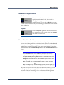
TeraMaster User’s Manual
Rev. C
April 2000
12120 Kear Place, Poway, CA 92064 USA
© 1998, 1999, 2000 by SeaSpace Corporation, Poway, California, 92064. Printed in the United States of America. All world rights
reserved. No part of this publication may be stored in a retrieval system, transmitted, or reproduced in any way, including, but not
limited to, photocopy, photograph, magnetic, or other record, without the prior written permission of SeaSpace Corporation.
This publication may contain or refer to information and products protected by copyrights or patents and does not convey any license
under the patent rights of SeaSpace Corporation nor the rights of others. SeaSpace Corporation, nor SeaSpace personnel, does not
assume any liability arising from any infringements of patents or other rights of third parties.
Any product names in this manual are trademarks or registered trademarks of their respective owners. The TeraScan product name
is a registered trademark of SeaSpace Corporation.
Representation and Warranty Disclaimer
For information about your TeraScan warranty, please refer to the “Terms and Conditions” statement
provided with your purchase order.
SeaSpace Corporation makes no claim to represent nor warrant, whether implied or otherwise, any
interpretation of images in this publication for forecasting weather conditions or for predicting
weather conditions. SeaSpace Corporation, nor SeaSpace personnel, makes no warranty of any kind
in regard to this material, including, but not limited to, the implied warranties of merchantability and
fitness for a particular purpose. The information in this publication is believed to be accurate and
complete; however, it is provided for reference only. SeaSpace Corporation, nor SeaSpace personnel,
shall not be liable for errors contained herein or for incidental or consequential damages in
connection with the furnishing, performance, or use of this material. All specifications, as well as the
information contained in this publication, are subject to change without notice.
Revision History
S/W Version
Number
Manual Revision
Number
Date of
Publication
3.0
Rev. A
Dec. 1998
3.01
Rev. B
April 1999
3.1
Rev. C
April 2000
TeraMaster User’s Manual iii
How to Contact Customer Support at SeaSpace
If you experience problems with your TeraScan system or have questions
concerning TeraScan, you can contact Customer Support by telephone or fax or
via the Internet at the following addresses.
SeaSpace Corporation
12120 Kear Place
Poway, CA 92064, USA
Tel: (858)746-1160
Fax: (858)746-1199
Internet: [email protected]
Customer Support will best be able to help you if you provide them with the
following information.
•
The version number of your TeraMaster software.
•
To get this information, select Help from the TeraMaster main screen,
then select About from the Help menu. An information panel with the
version of your TeraMaster software will appear on the screen.
The version number of your TeraScan® software.
To get this information, call up the TeraScan Launchpad:
% launchpad &
Click on the Configuration tab, then click on the Licenses manager to
call up the TeraScan Software Manager. Then click on the Licenses tab
of the Software Manager.
On the lower portion of the panel, you will find the version number and
other system information as shown below.
software version number
The version number of your operating system. Enter:
% uname -sr
•
The hardware platform of your system. Enter:
% uname -i
iv SeaSpace Corporation
•
Any error message associated with the problem you are experiencing.
•
ALL standard output and any standard error associated with the
technique you are using. The best thing to do is to redirect all output to
a file and attach the file to the mail message.
•
For all problems concerning data acquisition, please include verbatim
output of the corresponding $PASSDIR/schedlog and $PASSDIR/logfiles/
schedjob.* files.
Table of Contents
The Roles of Masters in TeraScan........................................................................... 1
Using Masters in Conditional Pass Capture.................................................. 1
Using Masters in Conditional Pass Processing ............................................. 2
Using Masters for Selecting a Part of a Pass for Processing........................ 2
Using Masters as Base Maps for Registration ............................................... 2
Launching TeraMaster ............................................................................................. 3
Operations of the TeraMaster GUI......................................................................... 5
Creating a New Master..................................................................................... 5
Entering Values into Text Fields .............................................................. 5
Using the Bull’s-Eye and Scissors Tools.................................................. 6
Saving a New Master ........................................................................................ 7
Saving Changes to an Existing Master ........................................................... 8
Loading a Saved Master .................................................................................. 8
Exiting TeraMaster ............................................................................................ 9
Controls of the TeraMaster GUI ........................................................................... 10
The View Menu................................................................................................ 10
Fit To Window .......................................................................................... 10
Actual Size ................................................................................................. 10
Set Map Center To View Center............................................................. 10
Set View Center to Map Center.............................................................. 10
Options....................................................................................................... 10
Fields on the Options Dialog Box.................................................................. 11
Datum Options ......................................................................................... 11
Perspective Radius ................................................................................... 11
Center to Std. Parallel .............................................................................. 12
Button Bar Icons............................................................................................... 12
Set Center (The Bull’s-eye Tool) ............................................................. 12
Cut Out an Area (The Scissors Tool) ..................................................... 12
TeraMaster User’s Manual
v
Table of Contents
The World and Original Buttons................................................................... 13
World ......................................................................................................... 13
Original ..................................................................................................... 13
Size and Resolution Controls......................................................................... 13
Area Size .................................................................................................... 14
Pixel Size .................................................................................................... 14
Density ....................................................................................................... 15
Projection Options Drawer............................................................................. 15
Map.................................................................................................................... 16
Center Lat/Center Lon ............................................................................ 16
Pixel Width / Pixel Height ..................................................................... 16
View................................................................................................................... 16
Center Lat/Center Lon ............................................................................ 16
Area Width / Area Height...................................................................... 17
Rotation...................................................................................................... 18
Information....................................................................................................... 18
Apply................................................................................................................. 18
Undo .................................................................................................................. 18
Lat/Lon of Cursor Position............................................................................ 18
X Y (Pixel Sample and Line)........................................................................... 18
Map Projection Options ......................................................................................... 19
Rectangular....................................................................................................... 19
Mercator ............................................................................................................ 19
Stereographic.................................................................................................... 20
UTM................................................................................................................... 20
Orthographic .................................................................................................... 21
Polarstereo ........................................................................................................ 21
Polyconic........................................................................................................... 22
Albers Conic ..................................................................................................... 22
Lambert Conic.................................................................................................. 23
Lambert Azimuthal ......................................................................................... 23
Mollweide ......................................................................................................... 24
Equidistant Azimuthal.................................................................................... 24
vi SeaSpace Corporation
Making Masters
eraMaster is a TeraScan graphical user interface (GUI) for viewing,
creating, and modifying masters. A master is a TeraScan dataset that
delimits a geographical area of the earth and specifies a map projection
and a pixel resolution for the area.
T
Masters serve several purposes in TeraScan. This chapter first summarizes the
roles that masters play in TeraScan and then explains how to use the TeraMaster
GUI to create and modify masters. In TeraPGS, masters are known as areas of
interest (AOIs).
The Roles of Masters in TeraScan
Using Masters in Conditional Pass Capture
A master can be used to set up a pass-capture criterion by which passes are
scheduled for capture only if the satellite reaches a specified minimum elevation
relative to the center of the area defined by the master. In this way, data capture
can be limited to good-quality data relevant to the area defined by the master.
Passes from satellites deemed too low on the horizon to yield useful data will not
be captured.
You can set up a pass-capture conditional in TeraCapCon by designating a
master and a minimum elevation angle as part of an autoschedule record. Please
refer to Chapter 6 of the TeraCapCon User’s Manual to find how to do this.
TeraMaster User’s Manual
1
Making Masters
Using Masters in Conditional Pass Processing
A master can also be used to set up a data-processing criterion by which passes
are selected for processing only if the area of the earth covered by the pass
includes a minimum percentage of the area defined by the master. If the pass
does not include at least the specified percentage of the specified master, then
none of the data from the pass will be processed.
In TeraPGS, you can set up a pass-processing conditional by selecting a master
in the Area Of Interest field and then entering a value in the Min % Coverage
field of the TeraPGS product-definition interface. Please refer to the TeraPGS
User’s Manual for further information.
Using Masters for Selecting Part of a Pass for Processing
A master can also be used to select a portion of a pass for processing rather
than processing the whole pass. Data processing is limited to a line-by-sample
rectangle of data sufficient to cover the area defined by the master. A polar
satellite pass covers a large swath of the earth and therefore consists of a large
amount of data. Selecting a subset of the data for processing rather than
processing all the data in a pass can significantly shorten processing time and
save disk space because the resultant products are smaller.
For the purpose of illustration, we will say that we are interested in satellite
coverage of Southern California and Baja, Mexico. The pass we received covers
a much larger area that includes much of Canada and the Midwestern United
States. We create a master that delimits our area of interest and use it to select a
subset of the data from the pass as shown in Figure 1.
In TeraPGS, you can designate a subset of pass data for processing by selecting a
master in the Area Of Interest field, then selecting the subset option from the
AOI Usage field of the TeraPGS product-definition interface. Please refer to the
TeraPGS User’s Manual for further information.
Using Masters as Base Maps for Registration
Finally, a master is also used as the base map to which sensor-view data is
earth-located during the process of registration or remapping. In this stage of data
processing, the subset of data selected by the master (indicated by the dashedline rectangle in Figure 1) is registered by interpolation to an equally spaced
line/sample grid delimited by the master (indicated by the solid-line rectangle
in Figure 1).
In TeraPGS, you can specify the remapping of your data by selecting a master
from the Area Of Interest field and then selecting the remap option from the
AOI Usage field.
2 SeaSpace Corporation
Making Masters
Master or defined area of interest.
Step 1: The subset stage of
processing cuts out the area
of the pass indicated by the
dashed-line rectangle. This
is a line-by-sample portion of
data just sufficient to cover
the master.
Satellite pass coverage.
Step 2. The remap stage of
processing registers the data,
keeping only the data in the
area delimited by the master.
Figure 1: The Use of a Master in Subsetting and Remapping
Launching TeraMaster
To launch TeraMaster from the command line, enter:
tmaster &
(Press Return.)
If you are working from the TeraPGS GUI, you can launch TeraMaster by
clicking on the View/Create button of the GUI.
TeraMaster User’s Manual
3
Making Masters
To quickly move around the map, click on the
Bull’s-eye button and then on the map.
You can place your cursor in any of the text
fields and type in values. Type in a value and
then tab to the next field you want to change.
When you’ve completed all your entries, click
on Apply or press Return and TeraMaster will
update your master with the new values.
Figure 2: The TeraMaster Main Panel
4 SeaSpace Corporation
Making Masters
Operations of the TeraMaster GUI
Creating a New Master
There are a number of ways to create a new master. Here we present two
possible ways to go about it. Keep in mind that some of the steps presented can
be done in a different order. By working with TeraMaster, you will discover the
methods that work best for you.
Entering Values into Text Fields
If you know the exact specifications of your master, you can create your master
simply by entering numerical values into the text fields provided on TeraMaster
as follows:
1. Click on File in the menu bar at the top of the TeraMaster panel and
select New from the File menu.
2. Choose a map projection from the Projection menu.
3. Specify the center of the master by entering the center coordinates into
the Map Center Lat and Center Lon fields.
4. Specify pixel size (in kilometers) by entering values in the Map Pixel
Width and Pixel Height fields.
5. Specify area width in pixels by entering values in the View Area Width
and Area Height fields.
6. From the View menu, click on Actual Size to see the actual size of your
master as you are working on it. (Select Fit to Window from the View
menu to again see the full extents of your master.)
7. Save your master (see “Saving a New Master” on page 7).
TeraMaster User’s Manual
5
Making Masters
Using the Bull’s-Eye and Scissors Tools
One way to create a master is to use the Bull’s-eye tool to quickly get to the
approximate area you want for the master, then use the Scissors tool to cut out
the area you want for your master.
1. Click on File in the menu bar at the top of the TeraMaster panel, then
click on New from the File menu.
2. Choose a map projection from the Projection menu.
3. The Bull’s-eye tool
at the top left of the TeraMaster panel is
on by default. With the Bull’s-eye tool active, you can use your cursor
to reposition the World map. When you click on the map, the world will
turn to bring the point you clicked on to the center of the display area.
You will notice that as you move the cursor around in the display area,
TeraMaster reports the latitude and longitude coordinates of your cursor
in the Lat and Lon fields on the lower left of the TeraMaster panel. Also,
as you move the cursor in the display area, notice that TeraMaster
always keeps North up.
4. Click on the Scissors button
.
5. Place your cursor on the map then press and hold down the left mouse
button as you drag the cursor to form a box around the area you want in
your master. When you release the mouse button, the display area will
update to show you the master you have cut out.
6. Use the Density buttons to adjust pixel size while maintaining the area
size of the master.
7. Adjust the center of the master, if needed, by selecting the Bull’s-eye tool
again and clicking at the point you want for the center.
8. From the View menu, select Set Map Center to View Center.
9. From the View menu, click on Actual Size to see the actual size of your
master as you are working on it. (Select Fit to Window from the View
menu to again see the full extents of your master.)
10. Save your master (see “Saving a New Master” which follows).
6 SeaSpace Corporation
Making Masters
Saving a New Master
To save a new master:
1. Click on File in the menu bar at the top of the TeraMaster panel and
select Save. The File Save dialog box will appear (Figure 3).
2. In the Filter field at the top of the File Save dialog box, specify the
directory in which your master is to be saved:
• In the Filter field, type the full path name to the directory, followed
by a slash and an asterisk (/*), and press Return.
• Or select the directory from the Directories tree. (Double-click on a
directory to select it. The name of the directory you click on will
appear in the Filter field and its subdirectories will be listed.
Double-click on the directory name ending in two periods (..) to
move up one level.)
Figure 3: The File Save Dialog Box
1. Enter the full path name of the directory
where the master is to be saved.
2. Type in a name for the master
here.
TeraMaster User’s Manual
7
Making Masters
3. In the Selection field at the bottom of the File Save dialog box, type in a
name for the master.
Use only uppercase and lowercase letters, numbers, underscores,
hyphens, and periods in the master name. Other characters may have
special meaning to the shell environment in which TeraScan operates.
4. Click on OK. Your master should now be saved in the directory you
specified.
Saving Changes to an Existing Master
To save changes to a master:
1. Click on File in the menu bar at the top of the TeraMaster window.
A pull-down menu will appear.
2. Click on Save.
Loading a Saved Master
To load a saved master into the display area of TeraMaster:
1. Click on File in the menu bar at the top of the TeraMaster panel, then
click on Open. The File Open dialog box will appear (Figure 4).
2. The File Open dialog box may open to the directory containing your
masters. If not, you will have to specify the directory where your
masters are stored.
• In the Filter field at the top of the File Open dialog box, type the full
path name to the directory containing your masters, followed by a
slash and an asterisk (/*), and press Return.
• Or select the directory from the Directories tree. (Double-click on a
directory to select it. The name of the directory you click on will
appear in the Filter field and its subdirectories will be listed.
Double-click on the directory name ending in two periods (..) to
move up one level.)
All the files in the directory you specified will be listed in the right-hand
column of the File Open dialog box.
8 SeaSpace Corporation
Making Masters
3. Highlight the name of the master file from the right-hand column and
click on OK. The master you selected will appear in TeraMaster’s
display area.
Alternatively, if you know the exact name and location of the file you
want to use, you can type that path into the Selection field at the bottom
of the File Open dialog box and click on OK to load a master.
1. Enter the full path name of the
directory in which the master you want to
load is stored. End the path name with /*
2. Select the master
you want to load.
Figure 4: File Open Dialog Box
Exiting TeraMaster
To exit TeraMaster:
1. Click on File in the menu bar at the top of the TeraMaster window.
A pull-down menu will appear.
2. Click on Quit.
TeraMaster User’s Manual
9
Making Masters
Controls of the TeraMaster GUI
The View Menu
Fit To Window
Clicking on Fit To Window will re-size your current master so that the entire
master fits within the TeraMaster display area.
Actual Size
Clicking on Actual Size will show you the final size of your master and of an
image registered to the master. The master may extend beyond the edges of the
display area. If so, you can use the scroll bars of the display area to see parts of
the master that are out of view.
Set Map Center To View Center
If you have defined a new view center, either by using the Scissors tool or by
entering values directly into the View Center Lat and Center Lon fields, then
clicking on Set Map Center To View Center will reset the map center to be the
same as the view center. This will be reflected in the values shown in the Map
Center Lat and Center Lon fields.
Set View Center to Map Center
If you have defined a new view center, either by using the Scissors tool or by
entering values directly into the View Center Lat and Center Lon fields, then
clicking on Set View Center To Map Center will reset the view center to be the
same as the map center. This will be reflected in the values of the View Center
Lat and Center Lon fields.
Options
The Options selection of the View menu brings up the Options dialog box
(Figure 5), from which you can specify a datum other than the default and set
other datum-related options for your master. A datum is a mathematical
representation of the earth’s shape. Different datums work better with different
areas of the earth. Datums usually include as a part of their name the portion of
the planet with which they work best. For example, “Hong Kong 1963” is a
datum that was created with Hong Kong as a reference point in, you guessed
it, 1963.
The default datum is WGS-84 (World Geodetic System 1984), which is also the
datum used by most Global Positioning Systems.
10 SeaSpace Corporation
Making Masters
If you are an expert user, you can define your own datum from the Options
dialog box. Enter the information in the appropriate fields and enter a unique
name. The new information will be saved with your master.
Fields on the Options Dialog Box
Any new settings made in the Options dialog box will be saved with the
individual master, and are not available globally.
Datum Options
Click on the Datum options drawer to select a datum from the list available. The
WGS-84 datum is the default. You may have to scroll up or down, using the
scroll bar located on the side of the options box, to see all of the available datums.
The Equatorial Radius and 1/Flattening fields will default from the datum you
selected in the Datum options drawer.
Perspective Radius
Perspective radius can be thought of as the distance from your eye to the image,
in this case the master area. If you are an expert user, you can enter a new
Perspective Radius. Otherwise, we recommend you use the default setting.
Figure 5: The Options Dialog Box
Select a datum from
this option box.
TeraMaster User’s Manual
11
Making Masters
Center to Std. Parallel
Enter a new standard parallel to apply to your master. If you are an expert user,
you can enter a new Center to Std. Parallel. Otherwise, we recommend you use
the default setting.
Button Bar Icons
At the top left of the TeraMaster panel, just below
the menu bar, is a button bar with two icons: The
Bull’s-eye and the Scissors icons.
Set Center (The Bull’s-eye Tool)
Click on the Bull’s-eye icon and then place your cursor on the map in the display
area. As you move your cursor about the map, the coordinates of the cursor
position will be reported in the Lat and Lon fields in the lower left of the
TeraMaster window. When you click on the map, the map will reposition itself
to bring the point you clicked on to the center of the display area. In this way,
you can quickly traverse the map and select an area for your master. As you
move about the display area, TeraMaster always keeps North up.
Cut Out an Area (The Scissors Tool)
The Scissors tool allows you to draw a box to select the area for a master. Click
on the Scissors icon, then press and hold down the left mouse button to set one
corner of the box. Drag the cursor to make a box that encompasses the area you
want to select. When you release the mouse button, TeraMaster will update the
display and report the center latitude and longitude in the View Center Lat and
Lon fields.
If you use the Scissors tool to cut out a master, the View Center of the master
will be different than the Map Center. See discussion under View Center,
starting on page 16.
12 SeaSpace Corporation
Making Masters
The World and Original Buttons
World
When you open TeraMaster, the default view in the
display area is the World view, shown with an
Orthographic map projection. As you create or
modify a master, you can click on World at any time
to return to the World view. Any unsaved changes you have made to the current
master will be lost.
Original
Click on Original to go back to the last saved master.
If no master has yet been saved, clicking on Original
will reload the World view.
Size and Resolution Controls
The Area Size, Pixel Size, and Density fields control pixel aspects of the master
area you are working with. For each of these fields, the larger, thicker Plus and
Minus symbols control gross changes, while the smaller, thinner symbols will
make changes in smaller increments. The changes made by these controls are
reflected in either the Pixel Width/Height fields or the Area Width/Height fields
or both.
The Information section of the TeraMaster panel (lower right corner)
reports the width and height of your master in kilometers. The Pixel Width
and Pixel Height fields in the Map section of the TeraMaster panel report
the pixel width and pixel height in kilometers. The Area Width and Area
Height fields in the View section of the TeraMaster panel report the width
and height of your master in number of pixels.
Map Pixel Width (km) × View Area Width (# pixels) = master width (km)
and
Map Pixel Height (km) × View Area Height (# pixels) = master height (km)
The pixel size of your master area can be matched to the telemetry you are
receiving. If you are processing AVHRR data, for example, your optimum
resolution would be a pixel height of 1.1 x 1.1 because AVHRR’s greatest
resolution is 1.1 kilometers at nadir.
TeraMaster User’s Manual
13
Making Masters
The lower the number of your pixel size, or resolution, the greater the size of
your dataset in terms of disk space. When processing an image, a smaller pixel
size, up to the maximum resolution, will result in a “cleaner” picture. A larger
pixel size, say 4x4 as opposed to 1.1x1.1, will result in a blockier image, but a
smaller dataset that takes up less disk space.
The Pixel Height/Width and Area Height/Width are reported on the right side
of the TeraMaster window. You can enter new values in the Height and Width
fields. Press Return or click on Apply after you type in the new values and the
display area will update accordingly.
You will notice that TeraMaster performs adaptive mapping as you zoom in or out,
displaying features as they become useful or taking them away when they are
not. TeraMaster will overlay geopolitical boundaries to include lakes, rivers, and
smaller bodies of water as they become large enough for consideration.
Area Size
The Area Size buttons can be used to change the Area Width
and Height of your master area.
Clicking on either of the Plus icons will increase the Area Width
and Height and act as a zoom-out function.
Clicking on either of the Minus icons will decrease the Area
Width and Height and act as a zoom-in function.
Pixel Size
The Pixel Size buttons can be used to change the Pixel Width
and Height of your master area.
Clicking on either of the Plus icons will increase the Pixel Width
and Height and act as a zoom-out function.
Clicking on either of the Minus icons will decrease the Pixel
Width and Height and act as a zoom-in function.
14 SeaSpace Corporation
Making Masters
Density
The Density buttons can be used to change the size of the pixels
without changing the overall size of your master.
Clicking on either of the Plus icons increases the number of
pixels in the master and decreases the size of the pixels. This will
be reflected by new values in the Area Width and Height fields
(which report the number of pixels to the width and height of
the master) as well as new values in the Pixel Width and
Height fields. The overall size of the master remains the same.
Clicking on either of the Minus icons decreases the number of pixels in the master
and increases the size of the pixels. This will be reflected by new values in the
Area Width and Height fields as well as in the Pixel Width and Height fields.
The overall size of the master remains the same.
Projection Options Drawer
You can select from a number of different map
projections for your master. Click on the
Projection options drawer to see the projections
available. Click on a projection to select it for
your master. All projections except Polar Stereo,
Lambert Conic, and Albers Conic are based on a
spherical earth. The three exceptions are based
on a geodetic or elliptical earth.
For all projections based on a spherical earth,
standard parallels coincide with the center
latitude of the projection.
Examples of each type of projection follow. Each
example projection has the same center latitude
and longitude of 32.52.60N by 117.12.00W
(sunny San Diego) and the same pixel size.
TeraMaster User’s Manual
15
Making Masters
Map
Center Lat/Center Lon
The Center Lat and Center Lon
fields under Map report the
coordinates of the point from
which a master is being viewed.
The Map center can be the same as
or different from the View center
(described under View below).
If the two centers are the same,
this means that the master is being viewed from the perspective of an observer
positioned over the center of the master. If the two centers are different, the
master is being viewed from a point that is different from the center of the
master.
You can change the Map center, either by entering different coordinates into the
Map Center Lat and Center Lon fields, or by clicking on the Bull’s-eye icon and
then clicking on the point you want as the Map center. The display area will
update to reflect the new center coordinates.
Pixel Width / Pixel Height
The Pixel Width and Pixel Height fields report the size of the pixels in your
master. You can type new values into the Pixel fields or you can change the
values by using the Pixel Size or Density controls. If you type in new values,
the display will update when you press the Return key or click on the Apply
button.
View
Center Lat/Center Lon
The Center Lat and Center Lon
fields under View report the
coordinates of the center point
of your master.
If you have used the Bull's-eye
tool to select the center of your
master, the values of the View
Center Lat and Center Lon fields
will match those of the Map
Center Lat and Center Lon fields.
16 SeaSpace Corporation
Making Masters
A. This master is seen from the perspective of
an observer positioned over the center of the
master. The Map center is the same as the View
center (63 N 150 W).
B. This master is seen from the perspective of
an observer positioned over San Diego,
California. The Map center (32 N 117 W) is
different from the View center (63 N 150 W).
Figure 6: A Master from Two Different Points of View
In this case, the master is seen from the perspective of an observer positioned
directly over the center of the master (Figure 6A).
If you have used the Scissors tool to cut out an area for your master, the View
center will be different from the Map center. In this case, the master will be seen
from the perspective of an observer positioned directly over the point designated
as the Map center (Figure 6B).
To reset your master so that the perspective is of an observer positioned over
the center of the master (Figure 6A), use the Set Map Center to View Center
option from the View menu to make the Map center the same as the View center.
Please refer to “Set Map Center To View Center,” starting on page 10 for more
information.
You can also change the View center or Map center by entering different
coordinates in the Center Lat and Center Lon fields.
Area Width / Area Height
The Area Width and Area Height fields report the width and height of the
master in pixels. You can type new values into these fields or change the values
by using the Area Size buttons. If you type in values, the master will update
when you click on the Apply button or press the Return key.
TeraMaster User’s Manual
17
Making Masters
Rotation
The Rotation field reports the angle (tilt) in degrees of the master. You can
change the orientation of the master by typing a new value into this field. The
master will update when you press the Return key or click on the Apply button.
Information
The Information box reports the Width and Height of your master in kilometers.
While in the default World view, these fields will remain blank.
Apply
You can enter information directly into text fields in TeraMaster. After you type
in new information, click on the Apply button or press the Return key to update
the TeraMaster display area.
Undo
Click on Undo to undo the last change made to the master you are working with.
Lat/Lon of Cursor Position
As you move the cursor around the map in the display area, TeraMaster reports
the cursor’s position in the Lat and Lon fields located in the lower left corner of
the panel.
X Y (Pixel Sample and Line)
The X and Y fields at the bottom of the TeraMaster window report the cursor’s
position relative to the pixels in the master. The X coordinate is the pixel sample,
i.e., the 1-relative pixel along the width of the master. The Y coordinate is the
pixel line, i.e., the 1-relative pixel from top to bottom of the master.
18 SeaSpace Corporation
Making Masters
Map Projection Options
Rectangular
A Rectangular map is an
unprojected image that is
formed by considering
latitude and longitude as
a simple rectangular
coordinate system.
Scale, distance, area, and
shape are all distorted,
with distortion
increasing toward the
poles.
Mercator
A Mercator projection is
a cylindrical projection
that displays the meridians of longitude
as evenly spaced vertical
lines. This type of projection is especially useful
in viewing equatorial
regions, though not the
Poles.
TeraMaster User’s Manual
19
Making Masters
Stereographic
The Stereographic
projection is a conformal
type projection with
scale increasing away
from the center of the
map. Distortion in area
and shape also increase
from the center. This
projection is mainly used
for polar maps.
UTM
The Universal Transverse Mercator, (UTM)
projection defines horizontal positions by
dividing the world into
six-degree zones.
20 SeaSpace Corporation
Making Masters
Orthographic
The Orthographic
projection is an
azimuthal projection
showing all meridians
and parallels as ellipses,
circles, or straight lines.
This projection can only
show one hemisphere at
a time, however, and has
severe distortion at the
edges.
Polarstereo
Another example of a
stereographic projection, the Polarstereo map
is centered at either Pole.
The polarstereo projection offers a true
perspective that is also
conformal. TeraMaster
locks the view around
either Pole using this
projection.
TeraMaster User’s Manual
21
Making Masters
Polyconic
The Polyconic projection
was used extensively by
the U.S. Geological
Survey in the early 20th
Century. It is neither
equal area nor
conformal. It is true to
scale along the central
meridian, while the
other meridians are
curved and distorted.
Albers Conic
The Albers Equal-Area
Conic projection is, as
the name implies, equal
area and conformal. This
projection is used extensively by the USGS. The
projection has concentric
arcs of circles for
parallels, which are not
evenly spaced.
22 SeaSpace Corporation
Making Masters
Lambert Conic
The Lambert Conic is
conformal, with parallels
made up of unequally
spaced arcs of concentric
circles spaced more
closely in the center of
the map. Scale is
normally true along two
standard parallels. The
meridians are equally
spaced radii of the same
circles and intersect the
parallels at right angles.
Lambert Azimuthal
The Lambert Azimuthal
projection is an equal-area
projection, which, in the
polar aspect, has a
straight-line central
meridian.
TeraMaster User’s Manual
23
Making Masters
Mollweide
The Mollweide projection
is generally used for world
maps. The central
meridian is straight, with
all others curved. The
parallels are straight but
unevenly spaced.
Equidistant Azimuthal
The Equidistant
Azimuthal projection is
also known as the polar
projection. Distances
measured from the center
of this projection are true.
Distances measured along
non-central radii are not
correct. The center of this
projection is the only point
without distortion.
24 SeaSpace Corporation
Making Masters
Definitions1
Conformity — A map projection is conformal
when the lines of meridian and parallels intersect
at right angles, and at any point the scale is the
same in every direction.
Equal Area — A map projection is equal area
when every part of the projection has the same
area, on a reduced scale, as the corresponding
part on the earth.
Linear Scale — The relation between distance
on a map projection and actual distance on earth.
Map — A two-dimensional representation of a
portion of the earth’s surface.
Projection — A simple geometric form that can
be flattened without stretching. Projections used
are cones, cylinders, and planes.
1. Map Projections Used by the U.S. Geological
Survey. Geological Survey Bulletin 1532, second
edition. John P. Snyder
TeraMaster User’s Manual
25
Making Masters
26 SeaSpace Corporation
Index
Numerics
D
1/flattening 11
datum, selecting 11
Density buttons 15
A
accessing TeraMaster 3
actual size of master 10
adaptive mapping 14
Albers equal-area conic map projection 22
AOI Usage 2
Apply button 18
area of interest 2
area size of master, changing 14
Area Width and Area Height fields 17
E
equatorial radius 11
equidistant azimuthal map projection 24
exiting TeraMaster 9
F
fit master to window 10
B
I
Bull’s-eye tool 6, 12
Information box 13
C
L
center lat/lon
map 16
view 16
center of master, setting 12
changing pixel size 16
controls in TeraMaster
Bull’s-eye tool 12
Scissors tool 12
size and resolution 13
creating a master 5
cutting out a master area 12
Lambert azimuthal map projection 23
Lambert conic map projection 23
launching TeraMaster 3
loading a master 8
M
map center 16
map definitions 25
map projections
Albers equal-area conic 22
TeraMaster User’s Manual I-1
Index
conformal 25
equal area 25
equidistant azimuthal 24
Lambert azimuthal 23
Lambert conic 23
linear scale 25
Mercator 19
Mollweide 24
orthographic 21
polarstereo 21
polyconic 22
rectangular 19
stereographic 20
masters
area size 14
as base maps for registration 2
changing area size 14
changing pixel size 14, 15, 16
creating 5
in conditional pass capture 1
in conditional pass processing 2
in remapping 2
loading 8
perspective 16
point of view 16
returning to last saved 13
rotating 18
saving 7
width and height 17
Mercator map projection 19
Mollweide map projection 24
R
O
W
Options dialog box 11, 12
Original button 13
original master, reloading 13
orthographic map projection 21
World button 13
rectangular map projection 19
remap 2
rotating a master 18
S
saving a master 7
Scissors tool 12
set map center to view center 10
set view center to map center 10
size and resolution controls 13
Area Size buttons 14
Density buttons 15
Pixel Size buttons 14
starting TeraMaster 3
stereographic map projection 20
U
Undo button 18
V
view center 16
Center Lat/Center Lon 16
set map center to view center 17
View menu 10
X
X Y fields 18
P
perspective for master 16
perspective radius 11
pixel density of master, changing 15
pixel size of master, changing 14, 15, 16
point of view 16
point of view for master 16
polarstereo map projection 21
polyconic map projection 22
I-2 SeaSpace Corporation