1
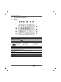
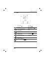
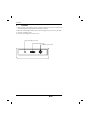
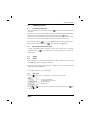
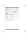
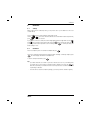
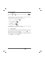
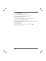
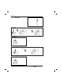
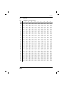
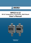
Operating Instructions
ProLine
Conductivity meter B250
Contents
Contents
1.
Introduction
3
2.
Safety measures
3
3.
Description of the instrument
3.1
Display
3.2
Keypad
4
4
5
4.
Installation
6
5.
Sample Measurement
5.1
Conductivity measurement
5.2
TDS/salinity/resistivity measurement
5.3
Settings
7
7
7
7
6.
Calibration
6.1
Settings
6.2
Calibration
9
9
9
7.
Self-diagnosis
10
8.
Battery operation
10
9.
Error messages
11
10.
Maintenance
10.1
Meter maintenance
10.2
Disposal
12
12
12
11.
Accessories
13
12.
Technical data
14
13.
Quick guide
16
14.
Appendix
14.1
Temperature correction factors f25
14.2
Conductivity standards
14.3
Practical salinity scale (UNESCO 1978)
14.4
Conductivity to TDS conversion factors
17
17
18
18
18
ProLine conductivity
1
2
ProLine conductivity
Introduction / Safety measures
1.
Introduction
The QiS ProLine conductivity meter is an instrument offering far more than simple conductivity measurements without breaking your budget. It is an instrument with many advantages:
- ProLine saves you time. The user interface is designed in such a logical way that you will no longer
need to consult your user manual.
- ProLine can be battery operated. Thanks to this option you can now easily move your instrument
from one working area to another even if no power supply is available.
- ProLine has additional advantages. Our Service Option provides regular equipment qualifications that
will improve the reliability and accuracy of your instrument.
2.
Safety measures
Measures for your protection
- Never work in an environment subject to explosion hazards! The housing of the instrument is not gas tight (explosion hazard due to spark formation, corrosion caused by
the ingress of gases).
- When using chemicals and solvents, comply with the instructions of the producer and
the general lab safety rules!
Measures for operational safety
- Have the instrument serviced only by QiS Service!
- Always wipe off splashed liquids immediately! The instrument is not waterproof.
- Use batteries of the specified type only. Otherwise, proper operation cannot be guaranteed.
- Exclude the following environmental influences:
• powerful vibrations,
• direct sunlight,
• atmospheric humidity greater than 80%,
• corrosive gases,
• temperatures below 5 °C and above 40 °C,
• powerful electric or magnetic fields !
ProLine conductivity
3
Description of the instrument
3.
Description of the instrument
3.1
Display
1 Battery status
2 Auto-off override during battery operation
3 Data transfer to PC/printer
4 Reference temperature
5 Meter self-diagnosis
Self-diagnosis
indicator
6
7
8
9
10
11
12
13
4
Indication to
press key
Error index
Conductivity/TDS/SAL/RES reading
Auto/manual temperature compensation
Endpoint stability/automatic endpoint
Endpoint stability
A
Temperature
Calibration standards & cell constant
Temperature correction method
Menu setting
Self-diagnosis
passed
Automatic endpoint
ProLine conductivity
Description of the instrument
3.2
Keypad
Press & release
Press & hold
for 2 seconds
Meter On/Off.
Auto-off override during
battery operation.
- Start or endpoint measurement
- Return to measurement mode
- Confirm setting
- Store entered value
Turn autom. endpoint on/off.
/
Start calibration.
Switch between conductivity, TDS,
salinity and resistivity
measurement modes.
Data transfer to
PC or printer.
Select calibration standard.
Increase value during setting.
Display cell constant during
measurement.
Start menu setting.
Decrease value during setting.
Measure
Start meter self-diagnosis.
ProLine conductivity
5
Installation
4.
Installation
1. Unpack the meter, power adapter, electrode, electrode arm and other accessories according to the
enclosed packing list. Keep the calibration certificate in a safe place.
2. Make sure the power adapter matches your local power supply. If not, please contact your vendor.
3. Connect the conductivity sensor.
4. Connect the power supply unit to the DC socket.
DC power supply unit socket
RS232 data output socket
Conductivity sensor socket
6
ProLine conductivity
Sample measurement
5.
Sample Measurement
5.1
Conductivity measurement
Place the conductivity sensor in the sample and press
to start the measurement: The decimal
point flashes.
The display shows the conductivity of the sample. The automatic endpoint A is the meter‘s default setting.
When the sensor output has stabilized, the display freezes automatically, and appears.
The automatic endpoint algorithm is as follows: The measured conductivity of the sample may not deviate
by more than 0.4% from the measured average conductivity of the probe of over 6 seconds.
By pressing and holding the
key, you can toggle between auto and manual endpoint mode. To
manually endpoint a measurement, press
, the display freezes, and appears.
5.2
TDS/salinity/resistivity measurement
To perform a TDS/salinity/resistivity measurement, follow the same procedure as for a conductivity
measurement. Press the
key to switch between conductivity, TDS, salinity and resistivity measurement modes.
5.3
Settings
5.3.1
ATC/MTC
Most conductivity sensors have a built-in temperature probe. When a temperature probe is used, the
symbol ATC and the sample temperature are displayed.
When the meter does not detect a temperature probe, it automatically switches to manual temperature
compensation mode, and MTC appears.
To set the MTC temperature, see 5.3.2 Menu setting.
5.3.2
Menu setting
Press the
key, the menu’s content appears on screen and the first item blinks:
Set reference temperature
Set temperature correction mode
Set MTC temperatur
Set TDS factor
Use the
or
to start the setting.
key to select a menu item. When the desired item blinks, press the
ProLine conductivity
key
7
Sample measurement
Set reference temperature:
When
appears and the current reference temperature blinks, use the
toggle between 25 °C and 20 °C. Press the
key to confirm your selection.
or
key to
Set temperature correction method:
When
appears and the current setting blinks, use the
or
key to toggle between
key to confirm your selection.
linear and nLF (nonlinear factor compensation). Press the
If you choose the linear temperature correction method, the current temperature coefficient appears. Use
the
and
keys to increase or decrease the value. Press
to confirm your setting.
Set MTC temperature:
When
appears, use the
temperature for your sample. Press the
25 °C.
and
keys to increase or decrease the value of the
key to confirm your setting. The default setting is
Set TDS factor:
When the current TDS factor appears, use the
Press the
5.3.3
and
keys to increase or decrease the value.
key to confirm your setting.
Data output
If a PC or printer is connected, every endpointed reading is sent to the PC or printed via the RS232
interface.
By pressing and holding the
key,
appears. The meter sends out a reading every second
until it endpoints.
8
ProLine conductivity
Calibration
6.
Calibration
6.1
Settings
When using the ProLine conductivity meter, you only need to do a 1-point calibration or enter a cell
constant directly.
key. The current calibration setting starts to blink.
Press the
Use the
or
key to select other items either above or below. When the desired option blinks,
to confirm your selection.
press
If you choose to set the cell constant, the current setting appears and the first digit blinks. Use the
keys to increase or decrease the value. Press the
key to confirm your setting. To finish
and
your setting, follow the same procedure to set the next digits. Press
to confirm your setting. The
default setting is 1.000.
6.2
Calibration
Place the conductivity sensor in a calibration standard and press
.
The ProLine conductivity meter automatically endpoints when calibrating. To manually endpoint, press
. The meter displays and freezes the standard value.
To return to sample measurement, press
.
Note
- If you have entered the cell constant of your sensor and choose to use it for your measurement,
you actually do not need to perform a calibration with a standard. If you press the
key
under this circumstance, the instrument shows the currently entered cell constant’s value instead
of performing a calibration.
- To ensure the most accurate conductivity readings, you need to perform a calibration regularly.
ProLine conductivity
9
Self-diagnosis / Battery operation
7.
Self-diagnosis
Press and hold
pears.
and
simultaneously until the meter’s self-diagnosis icon
ap-
The meter displays the full screen first, then each icon will blink one after the other. The final step is to
check that the keys function. This requires the user‘s cooperation.
blinks, press the corresponding key within 10 seconds.
When the icon
a. When
b. When
c. When
d. When
e. When
flashes, press the
flashes, press the
key.
flashes, press the
flashes, press the
flashes, press the
key.
key.
key.
key.
When self-diagnosis is completed, a
icon appears. If self-diagnosis failed, turn to "9. Error messages"
in these Operating Instructions for the proper action(s) to be taken.
8.
Battery operation
The ProLine conductivity meter offers optional battery operation. Install 4 AA batteries in the rear of the meter. If the power adapter is disconnected, the meter is operated by battery and the
icon appears.
When the batteries lose power, the meter displays
.
During battery operation, the meter has an auto-off function. If no key is pressed during the next 10 minutes, the meter will automatically switch off to save battery power. To override the auto-off function, press
and hold the
key for 2 seconds until
appears.
10
ProLine conductivity
Error messages
9.
Error messages
Error 1 - Conductivity measuring value out of range
Check if the sensor is properly connected and placed in a sample solution.
Error 2 - Temperature measuring value out of range (–5...105 °C)
Keep the sample temperature within the range.
Error 3 - The measured calibration standard temperature is out of the range (0...35 °C )
Keep the calibration standard temperature within the range.
Error 4 - In nLF temperature correction mode, temperature measuring value out of range (0...35 °C)
Keep the sample temperature within the range.
Error 5 - Self-diagnosis failed
Repeat self-diagnosis and make sure that you press the correct keys while the
blinking. If Err 5 still appears, call QiS service.
ProLine conductivity
icon is
11
Maintenance
10.
Maintenance
10.1
Meter maintenance
There are no user-replaceable parts in the meter or power supply unit. Do not remove the covers.
The ProLine conductivity meter needs no maintenance except for an occasional wipe with a damp cloth.
The housing is made of ABS/PC, which is attacked by some organic solvents, such as toluene, xylene
and methyl ethyl ketone. It is good laboratory practice to wipe away any spillage immediately.
Note
To prevent static damage to the instrument, always disconnect the conductivity sensor from the meter
before cleaning the sensor.
10.2
Disposal
In conformance with the European Directive 2002/96/ EC on Waste Electrical and Electronic
Equipment (WEEE) this device may not be disposed of in domestic waste. This also applies
to countries outside the EU, per their specific requirements.
Please dispose of this product in accordance with local regulations at the collecting point
specified for electrical and electronic equipment.
If you have any questions, please contact the responsible authority or the distributor from which you
purchased this device.
Should this device be passed on to other parties (for private or professional use), the content of this
regulation must also be related.
Thank you for your contribution to environmental protection.
12
ProLine conductivity
Accessories
11.
Accessories
Order no.
Power supply EU
Power supply UK
Power supply US
QA8550X
QA8560X
QA8570X
Swing arm electrode holder
Printer
Printer paper, pk/5
Printer cable
QA854X
QA8060X
QA8070X
QA8080X
Conductivity standard 1413 µS/cm, 500ml
Conductivity standard 12.88 mS/cm, 500ml
Conductivity standard 111.8 mS/cm, 500ml
QS950X
QS951X
QS1012
Conductivity electrode 4-pole, temperature sensor, epoxy
Conductivity electrode 4-pole, temperature sensor, glass
Through flow cell
QC2260T
QC2210T
QA853X
ProLine conductivity
13
Technical data
12.
Technical data
Conductivity measurement
Measurement range
Resolution
Limits of error
Selectable reference temperature
Linear correction
Nonlinear correction (DIN38404)
Calibration standard
Auto range
0.00 µS/cm…19.99 µs/cm
20.0 µS/cm…199.9 µS/cm
200 µS/cm…1999 µS/cm
2.00 mS/cm…19.99 mS/cm
20.0 mS/cm…199.9 mS/cm
200 mS/cm…500 mS/cm
±0.5 % of measured value
20 °C or 25 °C
Yes
Yes
1-point (84 µS/cm, 1413 µS/cm, 12.88 mS/cm)
TDS measurement
Measurement range
Resolution
Relative accuracy
Adjustable solids factor
0.0 mg/L ... 500 g/L
Auto ranging, same as conductivity
± 0.5%
0.4 ... 1.0
Salinity measurement
Measurement range (ppt)
0.00 ... 80.00
Resistivity measurement
Measurement range
0.00 Ω • cm ... 20 MΩ • cm
Temperature measurement
Temperature range
Temperature resolution
Temperature relative accuracy
–5.0 ... 105 °C
0.1 °C
± 0.2 °C
Display
Liquid crystal
Outputs
RS232 serial,
Baud rate:
Data bit:
Stop bit:
Parity:
1200
8
1
none
Ambient temperature:
Relative humidity:
Installation category:
Pollution degree:
5 … 40 °C
5% … 80% (non-condensing)
II
2
Ambient conditions
14
ProLine conductivity
Technical data
Size/weight
180 x 180 x 65 mm / 0.61 kg
Materials
Housing:
Electrode stand:
Membrane keypad:
Power requirements
The ProLine conductivity meter is supplied
with an appropriate power supply unit:
- USA:
120 V / 60 Hz, 10 VA, 9 V DC
- Europe:
230 V / 50 Hz, 10 VA, 9 V DC
- UK:
240 V / 50 Hz, 10 VA, 9 V DC
- Japan:
110 V / 50 Hz, 10 VA, 9 V DC
- Australia:
240 V / 50 Hz, 10 VA, 9 V DC
- China:
220 V / 50 Hz, 10 VA, 9 V DC
- Battery (optional):
4 x AA (LR6)
Maximum relative humidity
80% for temperature up to 31 °C decreasing linearly to 50%
relative humidity at 40 °C.
ABS, PC enforced
ABS, PC enforced
Polyester
Note
The ProLine conductivity meter should only be operated with the power supply unit supplied, or with
batteries.
ProLine conductivity
15
Quick guide
13.
Quick guide
1. Prepare Sensor
2. Calibration
Auto enpoint or
Calibration
standard
Stir, then
leave
3. Rinse Sensor
4. Measure sample
Auto enpoint or
Sample
Stir, then
leave
5. Rinse sensor
16
ProLine conductivity
Appendix
14.
Appendix
14.1
Temperature correction factors f25
°C
0
1
2
3
4
5
6
7
8
9
10
11
12
13
14
15
16
17
18
19
20
21
22
23
24
25
26
27
28
29
30
31
32
33
34
35
.0
1.918
1.857
1.800
1.745
1.693
1.643
1.596
1.551
1.508
1.467
1.428
1.390
1.354
1.320
1.287
1.256
1.225
1.196
1.168
1.141
1.116
1.091
1.067
1.044
1.021
1.000
0.979
0.959
0.940
0.921
0.903
0.886
0.869
0.853
0.837
0.822
.1
1.912
1.851
1.794
1.740
1.688
1.638
1.591
1.547
1.504
1.463
1.424
1.387
1.351
1.317
1.284
1.253
1.222
1.193
1.166
1.139
1.113
1.088
1.064
1.041
1.019
0.998
0.977
0.957
0.938
0.920
0.902
0.884
0.867
0.851
0.835
0.820
.2
1.906
1.845
1.788
1.734
1.683
1.634
1.587
1.542
1.500
1.459
1.420
1.383
1.347
1.313
1.281
1.249
1.219
1.191
1.163
1.136
1.111
1.086
1.062
1.039
1.017
0.996
0.975
0.955
0.936
0.918
0.900
0.883
0.866
0.850
0.834
0.819
ProLine conductivity
.3
1.899
1.840
1.783
1.729
1.678
1.629
1.582
1.538
1.496
1.455
1.416
1.379
1.344
1.310
1.278
1.246
1.216
1.188
1.160
1.134
1.108
1.083
1.060
1.037
1.015
0.994
0.973
0.953
0.934
0.916
0.898
0.881
0.864
0.848
0.832
0.817
.4
1.893
1.834
1.777
1.724
1.673
1.624
1.578
1.534
1.491
1.451
1.413
1.376
1.341
1.307
1.274
1.243
1.214
1.185
1.157
1.131
1.105
1.081
1.057
1.035
1.013
0.992
0.971
0.952
0.933
0.914
0.896
0.879
0.863
0.846
0.831
0.816
.5
1.887
1.829
1.772
1.719
1.668
1.619
1.573
1.529
1.487
1.447
1.409
1.372
1.337
1.303
1.271
1.240
1.211
1.182
1.155
1.128
1.103
1.079
1.055
1.032
1.011
0.990
0.969
0.950
0.931
0.912
0.895
0.877
0.861
0.845
0.829
0.814
.6
1.881
1.822
1.766
1.713
1.663
1.615
1.569
1.525
1.483
1.443
1.405
1.369
1.334
1.300
1.268
1.237
1.208
1.179
1.152
1.126
1.101
1.076
1.053
1.030
1.008
0.987
0.967
0.948
0.929
0.911
0.893
0.876
0.859
0.843
0.828
0.813
.7
1.875
1.817
1.761
1.708
1.658
1.610
1.564
1.521
1.479
1.439
1.401
1.365
1.330
1.297
1.265
1.234
1.205
1.177
1.149
1.123
1.098
1.074
1.051
1.028
1.006
0.985
0.965
0.946
0.927
0.909
0.891
0.874
0.858
0.842
0.826
0.811
.8
1.869
1.811
1.756
1.703
1.653
1.605
1.560
1.516
1.475
1.436
1.398
1.362
1.327
1.294
1.262
1.231
1.202
1.174
1.147
1.121
1.096
1.071
1.048
1.026
1.004
0.983
0.963
0.944
0.925
0.907
0.889
0.872
0.856
0.840
0.825
0.810
.9
1.863
1.805
1.750
1.698
1.648
1.601
1.555
1.512
1.471
1.432
1.384
1.358
1.323
1.290
1.259
1.228
1.199
1.171
1.144
1.118
1.093
1.069
1.046
1.024
1.002
0.981
0.961
0.942
0.923
0.905
0.888
0.871
0.854
0.839
0.823
0.808
17
Appendix
14.2
t(°C)
0
10
15
20
25
30
35
14.3
Conductivity standards
84 µS/cm
46 µS/cm
60 µS/cm
68 µS/cm
76 µS/cm
84 µS/cm
93 µS/cm
102 µS/cm
1413 µS/cm
776 µS/cm
1020 µS/cm
1147 µS/cm
1278 µS/cm
1413 µS/cm
1552 µS/cm
1696 µS/cm
12.88 mS/cm
7.15 mS/cm
9.33 mS/cm
10.48 mS/cm
11.67 mS/cm
12.88 mS/cm
14.12 mS/cm
15.39 mS/cm
Practical salinity scale (UNESCO 1978)
In the conductivity meter the salinity is calculated according to the official definition of UNESCO 1978,
Therefore the salinity Spsu of a sample in psu (practical salinity unit) at standard atmospheric pressure
is calculated as follows:
a0 = 0.0080
a1 = -0.1692
a2 = 25.3851
a3 = 14.0941
a4 = -7.0261
a5 = 2.7081
b0 = 0.0005
b1 = -0.0056
b2 = -0.0066
b3 = -0.0375
b4 = 0.0636
b5 = -0.0144
k = 0.00162
(32.4356 g KCl per 1000 g of solution)
14.4
Conductivity to TDS conversion factors
Conductivity
at 25 °C
84 µS
447 µS
1413 µS
1500 µS
8974 µS
12.880 µS
15.000 µS
80 mS
18
TDS KCl
ppm value
Factor
40.38
0.5048
225.6
0.5047
744.7
0.527
757.1
0.5047
5101
0.5685
7447
0.5782
8759
0.5839
52.168
0.6521
TDS NaCl
ppm value
Factor
38.04
0.4755
215.5
0.4822
702.1
0.4969
737.1
0.4914
4487
0.5000
7230
0.5613
8532
0.5688
48.384
0.6048
ProLine conductivity
Quality certificate. Development, production and testing according to ISO9001.
Environmental management system according to ISO14001.
Worldwide service. Our extensive service network is among the best in the world and
ensures maximum availability and service life of your product.
European conformity. The CE conformity mark provides you with the assurance that
our products comply with the most recent EU directives.
On the Internet. You will quickly find lots of essential information about our products,
our services, and our company at
http://www.q-i-s.net
Bredaseweg 108a
4902 NS Oosterhout, NL
PO Box 173
4900 AD Oosterhout, NL
T. +31 (0)162 47 14 85
F. +31 (0)162 47 14 86
[email protected]
www.q-i-s.net
Subject to technical changes and to the availability
of the accessories supplied with the instruments.
Version 2007-01