1
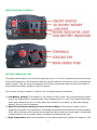
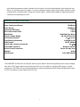
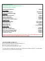
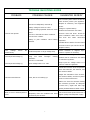
EVERHOME MODIFIED SINE WAVE POWER INVERTER DC 12V TO AC 120V 60HZ 300 Watt Installation Manual - Operating Instructions Congratulations. Your new EVG-300-12-120V-M Power Inverter is one of the most advanced and affordable DC to AC inverters available on the market today. This inverter, when used as described, will give you years of dependable service in your car, RV or boat. We have taken numerous measurements in quality control and in our manufacturing process to ensure that your product arrives in top condition, and that it will perform to your satisfaction. In the rare event that your Power Inverter maybe damaged or has a missing item, does not perform as specified, or requires warranty service, please attend our Warranty format attached. INTRODUCTION To get the most of your EVG-300-12-120V-M, proper installation is a critical issue. Please read the installation and operating instructions in this manual carefully before installing and using your inverter. Please pay special attention to the CAUTION statements in this manual. CAUTION statements identify conditions or practices which could result in damages to your inverter or to any other equipment. INSTALLATION The Battery power source must provide between 10 and 15 volts DC and must be able to supply sufficient current to operate the load and Inverter together. As a “rough guide line”, you may divide the power consumption of the load (in watts) by 10 to obtain the current (in amperes) the power source must be able to deliver. Example: Load is rated at 300 watts maximum for this model. Power source must be able to deliver: 300 divided by 10=30 amperes approximately. CAUTION: The Inverter must be connected only to batteries (or battery arrangement series or parallel) with a nominal output voltage of 12 volts. The Inverter will not operate from a 6 volts nominal DC battery voltage and will be damaged if it is connected to a 24 volts nominal DC battery voltage system. PLACEMENT OF THE INVERTER For best operating results, the inverter should be placed on a flat surface, such as the floor or a seat of the vehicle. Approximately 30’’ of DC (positive “red” and negative “black”) wires have been provided for this purpose. The inverter should only be used in locations that meet the following requirements: A.) DRY: Keep away from water. Do not allow water to drip or splash on the Inverter. B.) COOL: Ambient air temperature should be between 50 degrees and 80 degrees F. Do not place the 1 inverter on or near a heating vent or any piece of equipment which is generating heat above room temperature. Do not place the inverter in direct sunlight if avoidable. C.) VENTILATED: Allow at least one inch of clearance around the Inverter for air flow. Do not place anything on or over the inverter during operation. Make sure that air is allowed to circulate freely around the unit. D.) SAFE: Do not use the Inverter near flammable materials or in any location which may accumulate flammable fumes or gases, such as the battery compartment of your car, truck, RV or boat. E.) CONNECTING TO THE POWER SOURCE: Your Inverter is equipped alligator clips for connection to the power source, use only one power connection at a time. On the alligator clip, one clip is positive (RED) and the other is negative (BLACK). (See Fig.1 and Fig.2). CAUTION: DOES NOT USE WITH POSITIVE GROUND ELECTRICAL SYSTEMS. CAUTION: MAKE SURE THE INVERTER IS OFF WHEN CONNECTING THE WIRES. FIGURE 1: Loosen the caps on the terminals and slide the lugs between the cap and the base. Then Tighten. FIGURE 2: Open the alligator clips and close them over the appropriate battery terminals or connectors. Connect the RED ALLIGATOR CLIP TO THE (+) POSITIVE TERMINAL and the BLACK ALLIGATOR CLIP TO THE (-) NEGATIVE TERMINAL. 2 POWER RATING VERSUS ACTUAL USE OF EQUIPMENT Most electrical tools, appliances and audio/video equipment have a label indicating power consumption in amps or watts. Add up the power consumption in those items you will be using simultaneously, keeping total below 300 watts. If the power consumption is rated in amps, multiply by the AC volts (120) to determine the wattage. For example, a television rated at 0.9 amps will use 108 watts, well within the limits of what this inverter model can handle on a continuous basis. For more information regarding the typical wattage draws of many appliances, please refer to the table showed below. Resistive loads, such as incandescent lights, are the easiest for the inverter to drive, though larger resistive loads, such as electric stoves or heaters will require more power than this inverter model can deliver continuously. Inductive loads, such as TV’s and stereos (any device with a coil or a transformer in it) require more current to operate than a resistive load of the same power rating because inrush or instantaneous peak current consumptions. Induction motors (motors without brushes), as well as some televisions, may require 2 to 6 times their power rating to start up. This condition may require repeated “ON/OFF, ON/OFF, ON/OFF” switching of the power switch on your Inverter in order to get them started. The most demanding are those starts under load, i.e. compressors and pumps. Since motor and television characteristics vary widely, only experimentation will determine if a specific load can be started by this inverter and how long it can be running. CAUTION & IMPORTANT NOTE: The EVG-300-12-120V-M will not operate most appliances designed to produce heat, such as hair dryers, coffee makers, irons, heaters and toasters. The current use of most of these exceeds 1000 watts, far beyond the capacity of this unit. Turned either while engine is running or turned off. However, the inverter may not operate while the engine is starting, since the battery voltage can drop substantially during cranking. This inverter draws less than 0.4 ampere from the battery when it is not supplying power to the load. So, in most cases, this inverter may be left connected to the battery when it is not in use making this inverter perfectly suitable for solar applications since it draws so little current. If the vehicle will not be used for several days, disconnect the inverter from the battery. LOW BATTERY ALARM An alarm will sound when the voltage of the battery drops to 11±0.5 volts. This indicates that the battery requires charging. The user should stop operations at this time, since the inverter will shut down automatically when battery voltage drops to 10.0±0.5 volts. If the low battery alarm sounds when the battery is fully charged, follow the steps for correcting the lack of output power from the DC source in the Trouble Shooting Guide. The alarm will also sound when the inverter is overloaded, or if there is an excessive voltage drop between the battery and the inverter because using longer wires or with less thickness than the ones provided with this unit. NOTE: The alarm may sound momentarily when the unit is being connected to, or disconnected from, the power source. This is normal and does not indicate any problem. 3 INDICATORS AND CONTROLS BATTERY OPERATING TIME The typical vehicle battery has a minimum operating time of 1 to 2 hours, depending on the current use of the load being driven. We recommend that the operator start the vehicle every hour to recharge the battery system. This will prevent unexpected shut downs of equipment and will ensure that there is always sufficient battery capacity to start the engine. Your inverter circuitry constantly “monitors” the following hazardous conditions: A.) Low Battery Voltage: This condition is not harmful to the inverter, but could damage the power source. An audible alarm is sounded when input voltage drops to 11 volts. The inverter shuts down when input voltage drops to 10.0 volts. When the condition is corrected (i.e. alternator charges battery), the unit may be restarted. B.) Short Circuit-Reverse polarity or short circuit condition of the load will usually result in operating of the short circuit protection. Immediately disconnect the shorted circuit load and please check which problem could originate those conditions before using the inverter again. Several and repeated short circuit or reverse polarity conditions may damage the unit. C.) High Temperature: When the temperature of the internal heat sinks reaches 150 degrees F, the 4 solid-state temperature sensor located in the inverter circuit will automatically shut down the unit. Once it is allowed to get cool again, it may be restarted. Again please check which problem could originate that condition before using the inverter again. Several and repeated “high temperature” conditions may damage the unit. PRODUCT SPECIFICATIONS Max. Continuous Power Peak Power Optimum Efficiency No load Current Draw Waveform Input Voltage Range Low Battery Alarm Low Battery Shutdown USB Output Alarm and Thermal Shutdown Overload Protection Short Circuit Protection Weight Dimensions 300Watts 600Watts >85% <0.3A Modified Sine Wave 10-15/16Volts DC 11±0.5V DC 10.0±0.5V DC DC5V 500MA 65±5℃ Reset by switch Inline 35 amp fuse 0.8kg 185*105*60mm The INVERTER is fitted with a USB port which can be used for electrical appliances with output voltage less than 5V DC and output current less than 500 mA. It is ideal for charging MP3 players, mobile phones etc. CAUTION: Do not use the USB port for electrical appliances with output voltage higher than 5V DC and output current higher than 500 mA. 5 SAMPLE APPLICATION The products listed were operated normally with the EVG-300-12-120V-M: Toshiba Laptop Computer APPLIANCES: Singer Sewing machine Holmes 100 Watts Work-light CHARGERS: Ryobi 7.Volt Cordless drill Makita Cordless drill Motorola Cellular Phone JVC Camcorder (6 Volts 1200mA) POWER TOOLS: Black and Decker Buffer Dremel Motor Tool Stanley Glue Gun Weller Solder Gun AUDIO VIDEO: Hitachi 13” Color TV Quasar 20” TV/VCR Combo GE 9” Color TV/Cassette Combo Sharp Hi Fi Stereo 4/Head VCR Kenwood CD Charger 80watts 9A 99 Watts 100 Watts 8 35 25 23 Watts Watts Watts Watts 0.7A 77 Watts 0.9A 99 Watts 20 Watts 1.2A 132 Watts 72 Watts 220 Watts 65 Watts 40 Watts 60Watts Items that produce heat such as hair dryers, microwave ovens, and portable electric stoves require more power than the EVG-300-12-120V-M can supply. IN THE UNLIKELY EVENT OF .... You have an electrical installation problem, or There are any missing parts, or The trouble shooting guide didn’t help You can consult an expert who can help you. We will do our best to help you. In most cases we can solve your problem over the phone. 6 TROUBLE SHOOTING GUIDE PROBLEM: POSSIBLE CAUSES: SUGGESTED REMEDY Turn inverter power switch off and on until Inverter powers your appliance. Inverter not adequately warmed up. Battery voltage is below 10 volts. Equipment being operated draws too much power. Unit will not operate Inverter in thermal shut down condition. Inverter fuse is blown. Battery in poor condition. Have battery checked. Repeat as necessary until appliance starts. Charge or replace battery. Reduce load maximum 300 watts. Inverter must cool down. Check for good ventilation. Make sure load is less than 300 watts continuous operation. Call distributor-retailer for instructions on how to return your unit for service. Replace battery. Low Voltage Alarm On Continuously Low output AC Voltage (1) Insufficient power or large voltage drop. Using non RMS “average” reading voltmeter. condition of alligator clips. Clean or replace as necessary. Use True RMS reading meter. Reduce load to continuous 300 watts to maintain regulation. Inverter is overloaded. Low output AC Voltage (1) Check Input voltage below 11.0 volts. Keep input DC voltage above 11.0 volts to maintain regulation. Locate the inverter as far as possible from the television, the antenna, and the antenna cables. Adjust the orientation of the inverter, Television Interference Snow, Picture is breaking up. the antenna cables, and the TV power cord to reduce interference. Make sure that the antenna feeding the television provides an adequate (“snow free”) signal and that high quality shielded antenna cable is used. Buzz or Hum in Audio System is used The power supply in the device does not adequately filter the modified sine wave produced by the Inverter. 7 Use a sound audio system that uses a higher quality internal power supply. WARRANTY FORMAT Our Factory only sells products throughout distributor’s channels and guarantees all products to the distributors by covering only the repair or replacement procedure of any damaged part of the unit, for the time-period expressed in the distributor’s invoice. Factory provides standard warranty period of 1 year (Warranty period begins from the date on purchase invoice). Additional provision will be subject to contract. Additional warranty terms are available according to special sales contract. We will honor our warranty to our distributors thru our RMA format. The end user is subjected to the own distributor’s warranty format. Please consult your provider about its warranty terms. However, for all products, any warranty format for end users will never cover: • Damages than can occur to external equipment or devices, as well as any compensation for dismissed lucre. • Damages caused by external facts like: fire, water, generalized corrosion, biological infestations and by input voltages that create operating conditions beyond the maximum or minimum limits listed in the product specifications including high input voltage from generators and lightning strikes. • Damages caused by transportation. • Normal wear and tear of the product, and costs related to the removal, installation or troubleshooting of the customer’s electrical systems. • Damages caused by mistakes during installation procedures. • When unit presents repairing intention by NOT AUTHORIZED personnel. • When the explosion of any component of the surge suppression circuit causes any internal or external damage to the unit, in which case, the company considered the unit was operating correctly. • When the original identification markings of the product (trade-mark, serial number) have been defaced, altered or removed. All products featured in this user manual are easy to install. However, please make sure that licensed electricians verify the installation and follow all instructions indicated in the product user’s manuals and/or any “special instructions” written in the standard packages of the products. TECHNICAL INFORMATION DISCLAIMER Any technical information displayed in the company’s web page or in any written paper, catalog or user manual can be changed without previous notice. The company makes not warranty as to the accuracy, sufficiency or suitability of any technical or other information provided in any product manual or other documentation not of its own. Furthermore, our company assumes no responsibility or liability for loss or damage, whether direct, indirect, 8 consequential or incidental, which might arise out of the use of such information. The use of any such information will be entirely at the user’s or distributor’s risk. All products’ catalogs can be downloaded from the company’s web page. Some technical documents are also available to supplement the product information. Photos of some products would be slightly different of the final product you would receive. FACTORY CONTACT If you have any enquiries or technical problems concerning this inverter, please contact our customer services locally or to: EVERGREEN ENERGY SOLUTIONS LTD 19 Luard Road, Henan Building, 9th Floor Wanchai, Hong Kong Tel: 852-31834134. Fax: 852-31834154 [email protected] 9 10


![Manual[DOWNLOAD]](http://vs1.manualzilla.com/store/data/005897454_1-7b43247b19e54aa42c3777609ebafaf8-150x150.png)