1
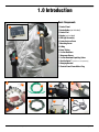
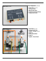
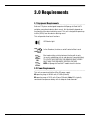
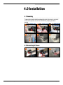
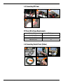
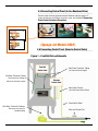
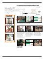
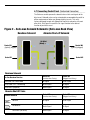
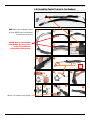
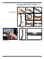
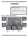
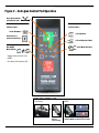
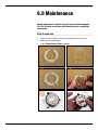
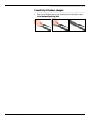
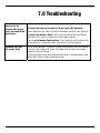
Safe-man
Productivity
System
™
Model:
Safe-man 2.0
Sponge-Jet, Inc.
235 Heritage Ave., Suite 2, Portsmouth, NH 03801 USA
+1-603-610-7950 / www.spongejet.com
Safe-man User Manual - 5 August 2010
Table of Contents
Section
Page
1.0
Introduction
3
2.0
Safety Checklist
5
3.0
Requirements
6
4.0
Installation
7
5.0
Operation
14
6.0
Maintenance
16
7.0
Troubleshooting
18
Notes
19
IMPORTANT NOTE: While parts, systems, components, operational procedures may be the same between
equipment models, the images provided in this manual may vary from model to model.
1.0 Introduction
Basic Components
1: Control Panel
1
2: Nozzle Holder (not included)
2
3: Control Pad
4: Nozzle (not included)
5: LED Light Assembly
6: Protective Lens Cover
7: Mounting Screw
8: O-Ring
4
9: Green Tubing
10: In-line Deadman
11: Neoprene Sleeve
3
12: In-line Deadman Equalizing Valve
5
13: Gorilla Cable™ (extensions sold separately)
14: Hanging Bracket
15: Control Panel Power Mains Plug
5
12
6
9
10
11
13
7
14
15
8
Safe-man User Manual - 5 August 2010
Page 3 of 19
Basic Components (continued)
Control Panel (front view)
16: Control Panel (front view)
16
17: DC Power Terminal
18: Mains AC Power Socket
19: Feed Unit Socket (Solenoid Valves)
20: Deadman Control Socket
20
19
18
17
21: Control Panel (rear view)
Control Panel (back view)
22: Deadman Solenoid Valve
IN-LINE DEADMAN VALVE:
MODE ON/OFF
ABRASIVE
CONTROL VALVE:
BLAST MODE ON/OFF
23: Signal Air – Deadman (Blasting)
24: Supply Air
25: Abrasive Solenoid Valve
26: Supply Air
22
23
27: Signal Air – Abrasive Control
25
21
24
Safe-man User Manual - 5 August 2010
26
27
Page 4 of 19
2.0 Safety Checklist
Safe-man User Manual - 5 August 2010
o
This Unit contains electrical and pressurized components which control a
pressurized system. Only trained operators should adjust, maintain and
repair it.
o
Be sure to observe all applicable safety requirements from the blast unit
manufacturer as well as industrial, local, state/province and government
regulations.
o
Inbound pressure should never exceed 8.6bar (125psi).
o
To prevent electrostatic buildup and possible electric discharge, the unit
must be grounded at the black DC Power Terminal.
o
Operators and people in proximity to blasting should always wear eye and
hearing protection with appropriate respiratory equipment and clothing,
which may depend on the type of coating or contaminant being removed.
o
Improper configuration and installation may cause unintentional start-up
and can result in personal injury. Contact Sponge-Jet Technical Services at
[email protected]/+1-603-610-7950 for assistance.
o
This unit is not designed to operate in heavy rain, snow or temperature
extremes.
Page 5 of 19
3.0 Requirements
3.1
Equipment Requirements
______________________________________________________________
Safe-man™ Systems are designed to operate with Sponge-Jet Feed Unit™s
and other conventional abrasive blast vessels. Unit functionality depends on
functionality of the abrasive blasting vessel. This unit is designed to operate up
to 91m (300 ft) from the abrasive blasting vessel.
This unit provides three basic functions:
LED Nozzle Light
In-line Deadman; functions as on/off control of blast vessel
OR
Blast mode setting switches between blasting with air only
(air wash) and blasting with air and abrasives (normal blasting).
TO UTILIZE THIS FUNCTION, THE ABRASIVE BLAST VESSEL
MUST HAVE THIS PNEUMATIC CONTROL FEATURE.
NOTE: all Sponge-Jet Feed Unit™ models have this feature.
3.2
Power Requirements
______________________________________________________________
This unit can operate with either AC or DC power supply.
AC operating range is 90-264 volts, 47-63Hz (80watts)
DC operating range is 10-15 volts 10amp (120watts). Note: DC is typically
connected to compressor battery with an adequate sized alternator.
Safe-man User Manual - 5 August 2010
Page 6 of 19
4.0 Installation
4.1 Grounding
______________________________________________________________
To prevent electrostatic buildup and possible electric discharge, harm to the
unit or to the operator, the unit must ALWAYS be properly grounded /
bonded.
1
2
3
4
5
6
4.2 Connecting AC Power
______________________________________________________________
1
Safe-man User Manual - 5 August 2010
2
3
Page 7 of 19
4.3 Connecting DC Power
______________________________________________________________
2
1
3
4
DC Power Wire Gauge Requirements
Maximum Distance
Wire Gauge
Up to 7.5m (25ft)
14
Up to 15m (50ft)
12
Up to 28m (75ft)
10
4.4
Connecting Control Panel (Cables)
______________________________________________________________
1b
1a
2
Rear View
3
A
A
Safe-man User Manual - 5 August 2010
Page 8 of 19
4.5 Connecting Control Panel (In-line Deadman Valve)
______________________________________________________________
Connect yellow twinlines where pneumatic Deadman typically connect. If
system architecture and fittings are not the same, see section 4.7 Connecting
Control Panel (Customized Connection).
Rear View
1
2
1
2
(Sponge-Jet Models ONLY)
4.6
Connecting Control Panel (Abrasive Control Valve)
______________________________________________________________
Figure 1 – Feed Unit Set-up Schematic
Feed Unit
Control Panel
Old Green Pneumatic Tubing
Disconnect from fittings at
both ends and leave in place.
New Green Pneumatic Tubing
(cut each section to length)
Safe-man
Control Panel
New Yellow Twinline
(from Safe-man Control Panel)
Green Gorilla Cable
Old Yellow Twinline & Deadman
Disconnect and store for
troubleshooting
Safe-man User Manual - 5 August 2010
Safe-man Control Pad
Page 9 of 19
4.6
Connecting Control Panel (Abrasive Control Valve)
______________________________________________________________
(continued)
For Sponge-Jet Models ONLY
1. Locate Green Tubing which connects to Feed Unit Auger Motor
2. Disconnect Green Tubing; do not discard
3. Follow Green Tubing to Feed Unit Control Panel, disconnect it;
Feed Unit Auger Motor
do not discard
4. Go to Step 5
How to Disconnect
Pneumatic Tubing
Control Panel
5
Feed Unit
Control Panel
Green
Pneumatic
Tube
6
1
Press tube down
Replace old Green Tubing Cut new Green Tubing to
with new Green Tube
needed length
7
2
Hold return ring down
3
Pull tube out
Insert new Green Tubing
from Feed Unit Control
Panel into Supply
of Abrasive Control
Solenoid Valve on
Safe-man Control Panel
10
8
Insert leftover new Green
Tubing into “Signal Air”
fitting of Abrasive Control
Solenoid Valve of Safeman Control Panel
9
Insert the other end
of new Green Tubing
into fitting that leads to
Feed Unit Auger Motor
11
Cut excess Green
Tubing if desired
Safe-man User Manual - 5 August 2010
Page 10 of 19
4.7
Connecting Control Panel (Customized Connection)
______________________________________________________________
The Safe-man controls pneumatic solenoid valves which send signals to the
blast vessel. Solenoid valves can be customized to accommodate the on/off or
off/on requirements of other non-Sponge-Jet blast vessels. This unit is
factory-configured to work with Sponge-Jet Feed Units and works with most
other units. Use Figure 2 to match the air signal function to the desired
function of your blast vessel.
Figure 2 – Safe-man Solenoid Schematic (Safe-man Back View)
Deadman Solenoid
Control D2
(typically plugged)
~
Abrasive Shut-off Solenoid
~~
Air Relief
(Bleed) =
~
Control D1
Control M2
(typically plugged)
~
Control M1
Supply
Deadman Solenoid
Control D1
Control D2
(Installed from Factory)
(Plugged from Factory)
Activated / ON – Blast Mode
Air Signal
No Air Signal
Inactivated / OFF – Not Blasting
No Air Signal
Air Signal
Shut Down (no power)
No Air Signal
Air Signal
Control M1
Control M2
(Installed from Factory)
(Plugged from Factory)
Abrasive
Air Signal
No Air Signal
No Abrasive
No Air Signal
Air Signal
Shut Down (no Power)
No Air Signal
Air Signal
In-line Deadman Function
Abrasive Shut-Off Valve
Control Pad Mode
Safe-man User Manual - 5 August 2010
Page 11 of 19
4.8
Assembling Control Pad and In-line Deadman
______________________________________________________________
NOTE: Adjust Safe-man Neoprene Sleeve
to lay flat. NEVER locate In-line Deadman
on inside curve of blast hose
CAUTION: Never use Safe-man when
In-line Deadman has severe creases
or folds. This condition can
uncontrollably activate blasting.
1
2.5cm (1in)
2
3
4
5
6
7
8
Optional - for infrequent nozzle changes
Safe-man User Manual - 5 August 2010
Page 12 of 19
4.8 Assembling Control Pad and In-line Deadman (continued)
______________________________________________________________
10
11
12
Open and close
Deadman Equalizing Valve
13
B
B
14
C
15
C
To Safe-man
Control Pad
To Safe-man
Control Panel
__________________________________________________________________________________________________
+
One end of Gorilla Cable
plugs into Safe-man
Safe-man User Manual - 5 August 2010
+
The other end of Gorilla Cable plugs into Gorilla Cable leading to Safe-man
Control Pad. Note: additional Gorilla™ cable extensions can be added as needed.
Page 13 of 19
5.0 Operation
Before Operating the Safe-man:
o
Verify the Feed Unit™ (blast vessel) is properly setup and operating
correctly – as directed by manufacturer.
o
Verify that unit is secured in an appropriate manner for operation.
o
Inspect all Blast Hoses and connections. Repair or replace worn or
damaged components. Ensure all couplings are equipped with coupling
gaskets, safety pins and hose restraints – and all are properly installed.
o
Insure blast vessel, its hoses and Safe-man black DC port are properly
grounded.
Figure 2 – Safe-man Control Panel Operation
(AC) Mains Power:
LIGHT:
Indicates Mains (AC)
Indicates LED
Power is connected
Nozzle Light is properly
OR
connected and operating
DC Battery Power:
NOZZLE:
Indicates Battery
Indicates Control Pad is
Power (12 volt DC)
properly connected
is connected
BLAST:
AIR ONLY:
STANDBY:
Indicates Air and
Abrasives are exiting
the Nozzle
Indicates Air only is
exiting Nozzle
Indicates neither Air
nor Abrasives and Air
are exiting the nozzle
Safe-man User Manual - 5 August 2010
Page 14 of 19
Figure 2 – Safe-man Control Pad Operation
Green Safety Switch =
and Indicator Light
Indicator lights…
Indicator lights…
In-line Deadman =
= Air Only Mode
Connection to a
powered control box =
= Air and Abrasives Mode
Red ON/OFF
Mode Switch =
= Blast Mode Activated
- Toggles Abrasive Cut-off Valve
ON/OFF.
- Also deactivates Deadman (Off).
USING THE CONTROL PAD
MODE
As a Deadman…
+
Press and Hold to Blast
Safe-man User Manual - 5 August 2010
Press and
Release
(Green Safety)
Press Switch and Release; toggles
between ON/OFF of abrasive shut-off valve
Page 15 of 19
6.0 Maintenance
Routine maintenance is required to provide long and reliable equipment
life. This Unit must be shut down and disconnected prior to conducting
maintenance.
Prior
to each use:
______________________________________________________________
Safe-man User Manual - 5 August 2010
•
Inspect all hoses, cables, connections and buttons for excessive or
abnormal wear and damage.
•
Inspect Protective Lens Cover for damage.
Page 16 of 19
If______________________________________________________________
sensitivity of Deadman changes:
•
Safe-man User Manual - 5 August 2010
Reset In-line Deadman pressure by removing and reinserting the cap on
In-line Deadman Equalizing Valve
Page 17 of 19
7.0 Troubleshooting
No nozzle output when
depressing In-line
Deadman and triggering
(press and release) Green
Safety Button
Check Control Panel indicator “Nozzle” light is illuminated.
If Control Panel indicator has power but “Nozzle” light is NOT illuminated…
Check connections from Control Pad to In-line Deadman and Gorilla Cable extensions.
If Control Panel Indicator “Nozzle” light is illuminated and Control Panel indicator
lights work when switches are depressed, inspect/replace solenoid.
Confirm In-line Deadman Equalizing Valve is tightly mounted, check for obstructions;
check rubber seal. If necessary remove, clean/replace, insert and re-tighten.
LED Nozzle Light shuts
off or blinks slowly
This is normal operation, IF Safe-man has been sitting without air flow from blasting.
To remain cool (in absence of air flow) LED Nozzle Light shuts down intermittently protecting it from overheating.
If LED Nozzle Light flashes during blasting and the nozzle is mounted properly at end
of the nozzle, inspect for loose connections to light.
Safe-man User Manual - 5 August 2010
Page 18 of 19
NOTES:
_____________________________________________________________
_____________________________________________________________
_____________________________________________________________
_____________________________________________________________
_____________________________________________________________
_____________________________________________________________
_____________________________________________________________
_____________________________________________________________
_____________________________________________________________
_____________________________________________________________
_____________________________________________________________
_____________________________________________________________
_____________________________________________________________
_____________________________________________________________
_____________________________________________________________
_____________________________________________________________
_____________________________________________________________
_____________________________________________________________
MODEL#: ______________________________________________________
SERIAL#: ______________________________________________________
Safe-man User Manual - 5 August 2010
Page 19 of 19


![Manual[DOWNLOAD]](http://vs1.manualzilla.com/store/data/005897454_1-7b43247b19e54aa42c3777609ebafaf8-150x150.png)