1
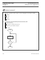
An Introduction to
Z80 Microprocessor Applications
DT202 Curriculum Manual
©2009 LJ Create. This publication is copyright and no
part of it may be adapted or reproduced in any material
form except with the prior written permission of LJ Create.
Lesson Module: 8.22/1
Issue: MP612/A
An Introduction to Z80
Microprocessor Applications
About this Module
About this Module
For tomorrow's engineers and technicians, training in the use of microprocessor
systems and the design of control tasks will be very important.
We see microprocessors used in almost every area of modern life. They control
domestic appliances, automated Teller machines, VCRs, automobile engine
management and braking systems and so on - the applications are endless. In
addition to these less obvious uses, microprocessors dominate today's' working
environment in the shape of the PC (personal computer).
To gain a good working knowledge of microprocessor technology you will need to
follow this manual carefully. It will lead you in a step by step manner through the
following areas:
!
!
!
!
!
!
!
!
!
!
!
!
!
!
!
Using the SAM microcomputer.
Introduction to Z80 programming.
Writing Machine Code Programs.
Program Debugging.
Using the Merlin Text Editor.
Introduction to Development Systems.
Addressing Modes.
Negative Binary Numbers.
Programs with Loops.
Further Programs with Loops.
Logical and Test Instructions.
Input and Output Programming.
Programming the Applications Module.
Stack and Subroutines.
Interrupts.
As you work through each chapter you will be guided by a series of student
objectives and your progress will be continually assessed by questions in the
Exercises, Practical Assignments and Student Assessments.
The Practical Assignments presented throughout the manual are graded in terms of
complexity, starting with simple machine code programs and ending with more
complex programming techniques in assembler code.
LJ Technical Systems
i
An Introduction to Z80
Microprocessor Applications
About this Module
Your instructor has a copy of the Solutions book for this manual. It contains all the
solutions to the assessment questions together with suggested solutions to all the
programming tasks. Copies of these programs are provided on a disk supplied with
the Solutions book.
What do I need to work through this manual?
To work through this manual you will need the following items:
1. SAM Z80 microprocessor board.
2. Merlin Development System software pack (6502/Z80 version) and RS232
cable.
3. Microprocessor Applications board.
4. Personal computer (PC) running Windows 95 or later, and fitted with RS232
serial communications (COM) port.
5. Two 0.1" shorting leads (supplied).
6. SAM Z80 User Manual.
7. Z80 Programming Manual.
8. Note pad and pencil.
In addition, you will need a power supply and a keypad/display unit. The form
that these items take will depend on whether you are using a Digiac 2000 system
or a Digiac 3000 system:
Digiac 2000 system
Digiac 3000 system
Power supply required
DT60 Power Supply unit
D3000 Experiment Platform or
D3000 Virtual Instrument
Platform
Keypad/display unit required
DT25 Keypad/display module
D3000-8.0 Microprocessor
Master Board with built-in
keypad/display
For further information, please refer to the SAM Z80 User Manual.
ii
LJ Technical Systems
An Introduction to Z80
Microprocessor Applications
About this Module
Computerized Assessment of Student Performance
If your laboratory is equipped with the D3000 Computer Based Training System,
then the system may be used to automatically monitor your progress as you work
through this manual.
If your instructor has asked you to use this facility, then you should key in your
responses to the questions in this manual at your computer managed workstation.
To remind you to do this, a
require a keyed-in response.
symbol is printed alongside questions that
The following D3000 Lesson Module is available for use with this manual:
D3000 Lesson Module 8.22
Additional Teachware
If you are encountering microprocessors for the first time, it is recommended that
you begin by reading the manual "An Introduction to Microprocessor
Technology", which is available from LJ Technical Systems.
Other manuals available in this range are:
An Introduction to 6502 Microprocessor Applications.
An Introduction to 6502 Microprocessor Troubleshooting.
An Introduction to Z80 Microprocessor Troubleshooting.
68000 Microprocessor Concepts and Applications.
An Introduction to 68000 Microprocessor Applications.
LJ Technical Systems
iii
About this Module
iv
An Introduction to Z80
Microprocessor Applications
LJ Technical Systems
An Introduction to Z80
Microprocessor Applications
Contents
Contents
Curriculum Text
Pages
Chapter 1
Using the SAM Microcomputer .................................................................. 1 - 20
Chapter 2
Introduction to Z80 Programming............................................................. 21 - 36
Chapter 3
Writing Machine Code Programs .............................................................. 37 - 56
Chapter 4
Program Debugging................................................................................... 57 - 66
Chapter 5
Using the Merlin Text Editor .................................................................... 67 - 78
Chapter 6
Introduction to Development Systems .................................................... 79 - 100
Chapter 7
Addressing Modes ................................................................................. 101 - 114
Chapter 8
Negative Binary Numbers ..................................................................... 115 - 124
Chapter 9
Programs with Loops............................................................................. 125 - 150
Chapter 10
Further Programs with Loops ................................................................ 151 - 162
Chapter 11
Logical and Test Instructions ................................................................ 163 - 182
Chapter 12
Input and Output Programming............................................................. 183 - 200
Chapter 13
Programming the Applications Module ................................................ 201 - 228
Chapter 14
Stack and Subroutines ........................................................................... 229 - 250
Chapter 15
Interrupts................................................................................................ 251 - 286
Continued ...
LJ Technical Systems
Contents
An Introduction to Z80
Microprocessor Applications
Appendices
Pages
Appendix 1
Standard Programming Sheet ................................................................ 287 - 288
Appendix 2
SAM System Calls ................................................................................ 289 - 300
Appendix 3
ASCII Codes.......................................................................................... 301 - 302
LJ Technical Systems
An Introduction to Z80
Microprocessor Applications
Chapter 9
Programs with Loops
Chapter 9
Programs with Loops
Objectives of
this Chapter
Having studied this chapter you will be able to:
Describe the different types of program loop structure.
Describe the use of the conditional and unconditional
instructions.
Explain the mechanism and use of Z80 relative
addressing.
Describe the function and operation of the following
Z80 flags:
Carry Flag
Zero Flag
Write programs that use the Z80 assembly language
conditional and unconditional Jump instructions.
Use the Z80 assembly language combined Decrement
and conditional Jump instructions.
Equipment
Required for
this Chapter
LJ Technical Systems
SAM Z80 Microcomputer.
Power supply.
Keypad/display unit.
Merlin Development System Software Pack, installed on a PC
running Windows 95 or later.
SAM Z80 User Manual.
125
Programs with Loops
Chapter 9
An Introduction to Z80
Microprocessor Applications
Introduction
Often it will be necessary to use a program loop to repeat a section of a program
a number of times. There are three main types of program loop:
1. Repeating a program section indefinitely.
For example: Output a “1” on bit 2 of a data port indefinitely.
Enter
Output a "1" on
Bit 2 of Data Port
2. Repeating a program section until some predetermined condition becomes
true.
For example: Waiting for a “1” to be input at bit 4 of a data port.
Enter
Read bit 4
of Data Port
Is
Bit 4
=1
?
Yes
No
Exit
126
LJ Technical Systems
An Introduction to Z80
Microprocessor Applications
Programs with Loops
Chapter 9
3. Repeating a program section for a predetermined number of passes.
For example: Output a “0” on bit 6 of a data port for the time it takes
to repeat a loop 5000 times.
Enter
Set Count to
5000
Output a "0" on
Bit 6 of Data Port
Reduce Count
by 1
Is
No
Count
=0?
Yes
Exit
If, in this example, each pass through the loop were to take 1µs, a "0" would be
output on bit 6 of the data port for 5ms.
In order to write assembly language programs with loops, it will be necessary to
use JUMP instructions.
9.1
JUMP Instructions
These instructions cause program execution to be continued from some point
other than the next location in sequence.
There are two types of JUMP instruction:
Unconditional JUMP
Conditional JUMP
LJ Technical Systems
-
“Always JUMP”
“Only JUMP if some condition is true”
127
Programs with Loops
Chapter 9
9.2
An Introduction to Z80
Microprocessor Applications
Relative Addressing
Some JUMP instructions can use Relative Addressing. In this mode of addressing,
the destination for the JUMP is not specified directly (for example, “location
4700H”) but is expressed in terms of the number of locations further on (or back)
in the program (for example, “8 locations further on"). The easiest means of
understanding this concept is to examine an example.
Recall the source program PROG2.ASM from Chapter 6. Load this program into
Merlin and modify each “JP” instruction to “JR”. A “JR” is a relative jump
instruction. Having modified the program, save it as PROG4.ASM (using the
Save As option from the File menu) and then assemble the program generating
the object program and listing. The listing will have the form shown below:
VAL1:
VAL2:
MEM1:
4500
4502
4504
4507
4508
450A
128
3E
18
32
C9
C6
18
02
04
00 50
03
F8
ORG 4500H
;Object code start addr
EQU 02H
EQU 03H
EQU 5000H
;Defines ‘VAL1’ as 02H
;Defines ‘VAL2’ as 03H
;Defines ‘MEM1’ as 5000H
BEGIN: LD A,VAL1
JR NEXT
LAST:
LD (MEM1),A
RET
NEXT:
ADD A,VAL2
JR LAST
;Loads accum with 02H
;Jumps to ‘NEXT:’
;Saves accum in 5000H
;Return
;Adds 03H to accum
;Jumps to ‘LAST:’
LJ Technical Systems
An Introduction to Z80
Microprocessor Applications
Programs with Loops
Chapter 9
Consider the first relative jump JR NEXT.
The operand is 04H. This is often called the displacement or offset in relative
addressing. The offset indicates that the destination is 04H locations further on. It
is important to note that the program counter will already contain the address of
the next instruction (4504H). If 04H is added to this then the address of the
destination can be found:
4504H + 04H = 4508H
This is indeed the case above where ‘NEXT’ is 4508H.
Consider now the second relative jump JR LAST.
The offset is F8H. This is a negative number in 2’s complement notation.
F8H
= + 1111 10002
= - 0000 01112 (1’s complement)
= - 0000 10002 (2’s complement)
= - 08H
So this instruction will jump backwards 08H locations. Now, as before the
program counter will already hold the address of the next instruction (450CH in
this case):
450CH - 08H = 4504H
So this instruction will jump to 4504H. Check the program listing to see that this
is indeed the case.
Range of Relative Addressing
The largest positive offset will be 7FH (0111 11112), which is 12710. So it is not
possible to perform a relative jump more than 12710 locations in the forward
direction. The largest negative offset will be 80H (1000 00002).
80H
= + 1000 00002
= - 0111 11112 (1’s complement)
= - 1000 00002 (2’s complement)
= - 80H
= - 12810
So the limit of a backward relative jump is 12810 locations. The Z80 Cross
Assembler will produce an error message if a relative jump is out of range.
LJ Technical Systems
129
Programs with Loops
Chapter 9
9.2a
An Introduction to Z80
Microprocessor Applications
Z80 instructions, which allow programs to continue from a point other
than the next location in sequence, are called:
a continue instructions.
b jump instructions.
c sequence instructions.
d skip instructions.
9.2b
In relative addressing, the destination for a jump is specified by:
a a 2's complement displacement.
b a direct address.
c the contents of the flag register.
d the contents of the BC register pair.
130
LJ Technical Systems
An Introduction to Z80
Microprocessor Applications
9.3
Programs with Loops
Chapter 9
Conditional Jump Instructions
A conditional jump is only taken if some predetermined condition is true.
Otherwise the next instruction in sequence is executed. These instructions are
very important since they allow the microprocessor to take decisions. Conditional
jumps may use direct or relative addressing. The conditions, which these
instructions test, are the states of the flags.
Z80 Flags
Each flag is a single flip-flop, which can store a 0 or a 1. These flags indicate the
type of result from the last ALU operation. Many instructions will affect various
flags but a significant number do not (notably Load). The Z80 Programming
Manual explains which flags are affected by each instruction. The Z80 has 6 flags
but we shall only consider two for the time being: the Carry Flag and the
Zero Flag:
1.
Carry Flag
This flag is set (that is = 1) if the last arithmetic operation produced a “carry out”.
For example:
If 3AH is added to 47H, the result is 81H and there is no carry out:
3AH
47H +
0011
0100
10102
01112 +
81H
1000
00012
However, if 3AH is added to E7H, the result is 121H. Thus a carry out is generated:
3AH
E7H +
121H
1
0011
1110
10102
01112 +
1010
00012
Carry out
Now, the accumulator can only hold 8 bits but this result is 9 bits in length. The 8
least significant bits (that is 21H) will be placed in the accumulator and the “9th
bit” in the carry flag, so, C=1.
The carry flag is also used as a “borrow” flag when performing subtraction.
LJ Technical Systems
131
Programs with Loops
Chapter 9
2.
An Introduction to Z80
Microprocessor Applications
Zero Flag
This flag is set (that is = 1) if the result of the last operation was zero.
For example, if the microprocessor subtracts 34H from 34H the result is 00H and
the zero flag is set (Z=1).
If 34H is added to 34H the result is 68H which is non-zero so the zero flag is
cleared (Z=0).
The action of these flags can be summarized thus:
Z
NZ
C
NC
Zero Result
Non-Zero Result
Carry Generated
No Carry Generated
(Z=1)
(Z=0)
(C=1)
(C=0)
Examples:
132
JP Z,4820H
;Jump to location 4820H if the
;zero flag is set (that is if Z=1)
;- Zero Result
JR NZ,SCAN1
;Jump to address specified by
;the label SCAN1 if the zero
;flag is clear(that is if Z=0)
;- Non-Zero Result
JR C,NEXT
;Jump to address specified by
;the label NEXT if the carry
;flag is set(that is if C=1)
;- Carry Generated
JP NC,LAST
;Jump to address specified by
;the label LAST if the carry
;flag is clear (that is if C=0)
;- No Carry Generated
LJ Technical Systems
An Introduction to Z80
Microprocessor Applications
Programs with Loops
Chapter 9
Now refer to your Z80 programming manual. Note how the Zero and Carry Flags
are affected by each instruction:
Instructions
Zero Flag
Carry Flag
LD
Not affected
Not affected
ADD
Set if result is zero; otherwise
cleared
Set if result exceeds 8 bits;
otherwise cleared
SUB
Set if result is zero; otherwise
cleared
Set if there is a ‘borrow’;
otherwise cleared
RET
Not affected
Not affected
JP
Not affected
Not affected
INC
Set if result is zero; otherwise
cleared
Not affected
DEC
Set if result is zero; otherwise
cleared
Not affected
LJ Technical Systems
133
Programs with Loops
Chapter 9
9.3a
An Introduction to Z80
Microprocessor Applications
After the Z80 has subtracted 4AH from 67H, the Zero (Z) and Carry (C)
flags will be:
a Z = 0, C = 0
b Z = 0, C = 1
c Z = 1, C = 0
d Z = 1, C = 1
9.3b
After the Z80 has added 52H to 67H, the Zero (Z) and Carry (C) flags
will be:
a Z = 0, C = 0
b Z = 0, C = 1
c Z = 1, C = 0
d Z = 1, C = 1
9.3c
After the Z80 has added 75H to 8EH, the Zero (Z) and Carry (C) flags
will be:
a Z = 0, C = 0
b Z = 0, C = 1
c Z = 1, C = 0
d Z = 1, C = 1
9.3d
After the Z80 has subtracted 72H from 72H, the Zero (Z) and Carry (C)
flags will be:
a Z = 0, C = 0
b Z = 0, C = 1
c Z = 1, C = 0
d Z = 1, C = 1
134
LJ Technical Systems
An Introduction to Z80
Microprocessor Applications
9.4
Programs with Loops
Chapter 9
Worked Example
Write a program that will add the contents of locations 5000H and 5001H. The
value 80H should be placed in location 5002H if the result exceeds FFH, otherwise
01H should be placed in location 5002H.
Solution:
This problem requires the carry flag to be tested following the addition and then a
marker value to be saved to indicate the status of the result.
START
Load the accumulator
from location 5000H
Add the contents of
location 5001H
to the Accumulator
Is the
Carry Flag
set?
YES
NO
Load the accumulator
with 01H
Load the accumulator
with 80H
Save the accumulator
to location 5002H
END
LJ Technical Systems
135
Programs with Loops
Chapter 9
An Introduction to Z80
Microprocessor Applications
The first part of this program will be quite simple:
LD A,(5000H)
;Loads accumulator from 5000H
Now, unfortunately direct addressing cannot be used with ADD. It is however
possible to ADD the contents of two registers so one way to overcome the
problem is to LOAD the B register from 5001H and then ADD the B register to
the accumulator.
A further problem now arises: It is not possible to load the B register using direct
addressing. This problem can be overcome thus:
LD A,(5000H)
;Loads accumulator from 5000H
;Add contents of 5001H to accumulator:
LD B,A
LD A,(5001H)
ADD A,B
;Loads the B reg from the accum
;Loads acc from 5001H
;Adds B reg to accumulator
The addition has now taken place and so we can test the carry flag thus:
LD A,(5000H)
;Loads accumulator from 5000H
;Add contents of 5001H to accumulator:
LD B,A
LD A,(5001H)
ADD A,B
;Loads the B reg from the accum
;Loads accumulator from 5001H
;Adds B reg to accumulator
;Test for carry flag set:
JR C,OVER
;If C=1, jump to label OVER
The state of the carry flag will now determine which branch is taken:
LD A,(5000H)
;Loads accumulator from 5000H
;Add contents of 5001H to accumulator:
LD B,A
LD A,(5001H)
ADD A,B
;Loads the B reg from the accum
;Loads accumulator from 5001H
;Adds B reg to accumulator
;Test for carry flag set:
JR C,OVER
;If C=1, jump to label OVER
;Load accumulator with appropriate marker value:
OVER:
136
LD A,01H
JR SAVE
LD A,80H
;C=0 so load marker for no carry
;Jump to label SAVE(Save marker)
;Load accumulator with
;marker for carry set
LJ Technical Systems
An Introduction to Z80
Microprocessor Applications
Programs with Loops
Chapter 9
All that is required now is to save the marker in location 5002H:
LD A,(5000H)
;Loads accumulator from 5000H
;Add contents of 5001H to accumulator:
LD B,A
LD A,(5001H)
ADD A,B
;Test for carry flag set:
JR C,OVER
;Loads the B reg from the accum
;Loads accumulator from 5001H
;Adds B reg to accumulator
;If C=1, jump to label OVER
;Load accumulator with appropriate marker value:
LD A,01H
JR SAVE
LD A,80H
OVER:
;C=0 so load marker for no carry
;Jump to label SAVE (Save marker)
;Load accumulator with
;marker for carry set
;Save marker value in location 5002H:
SAVE:
LD (5002H),A
RET
;Save marker in 5002H
;Return
Finally, it will be necessary to specify the start address for object code using
ORG:
ORG 4400H
;Start address for object code
LD A,(5000H)
;Loads accumulator from 5000H
;Add contents of 5001H to accumulator:
LD B,A
LD A,(5001H)
ADD A,B
;Loads the B reg from the accum
;Loads accumulator from 5001H
;Adds B reg to accumulator
;Test for carry flag set:
JR C,OVER
;If C=1, jump to label OVER
;Load accumulator with appropriate marker value:
OVER:
LD A,01H
JR SAVE
LD A,80H
;C=0 so load marker for no carry
;Jump to label SAVE (Save marker)
;Load accumulator with
;marker for carry set
;Save marker value in location 5002H:
SAVE:
LJ Technical Systems
LD (5002H),A
RET
;Save marker in 5002H
;Return
137
Programs with Loops
Chapter 9
9.4a
An Introduction to Z80
Microprocessor Applications
Load the program for Worked Example 9.4 into the SAM. Place the
value 67H in location 5000H and the value 7DH in location 5001H. Run
the program and examine the contents of location 5002H. Enter the
hexadecimal byte that you find.
Now, the first part of this program required a number of instructions to transfer
data from one register to another. This could have been avoided by using the HL
register pair to point to memory locations, since it is possible to ADD in this way.
Such a program is shown below:
ORG 4400H
;Start address for object code
LD HL,5000H
;HL points to 5000H
;Add contents of 5001H to accumulator:
LD A,(HL)
INC HL
ADD A,(HL)
;Loads the accumulator from 5000H
;HL now points to location 5001H
;Adds contents of 5001H to accum
;Test for carry flag set:
JR C,OVER
;If C=1, jump to label OVER
;Load accumulator with appropriate marker value:
LD A,01H
JR SAVE
OVER:
LD A,80H
;C=0 so load marker for no carry
;Jump to label SAVE (Save
;marker)
;Load accumulator with marker
;for carry set.
;Save marker value in location 5002H:
SAVE:
9.4b
Note:
138
INC HL
LD (HL),A
RET
;HL now points to 5002H
;Saves marker in 5002H
;Return
Load the program for Worked Example 9.4 into the SAM. Place the
value 82H in location 5000H and the value 9CH in location 5001H. Run
the program and examine the contents of location 5002H. Enter the
hexadecimal byte that you find.
It is good practice to use the HL register pair to point to data wherever possible
since this technique often takes fewer bytes of object code and less time to
complete instructions.
LJ Technical Systems
An Introduction to Z80
Microprocessor Applications
9.5
Programs with Loops
Chapter 9
Worked Example
Write a program that will add the contents of locations 5000H and 5001H. The
most significant byte of the result should be stored in location 5002H and the least
significant byte in location 5003H.
Solution:
START
Load the accumulator
from location 5000H
Add the contents of
location 5001H
to the Accumulator
Is the
Carry Flag
set?
NO
YES
Load the B register
with 01H
Load the B register
with 00H
Save the B register
to location 5002H
Save the Accumulator
to location 5003H
END
LJ Technical Systems
139
Programs with Loops
Chapter 9
An Introduction to Z80
Microprocessor Applications
Now, consider the largest possible values:
FFH + FFH = 01FEH
So the most significant byte can only be 00H or 01H.
Thus, the program must perform the addition, save the least significant byte and
then test the carry flag to determine whether the most significant byte is 00H or
01H.
ORG 4400H
;Start address for object code
LD HL,5000H
;Loads accumulator from 5000H
;Add contents of 5001H to accumulator:
LD A,(HL)
INC HL
ADD A,(HL)
;Loads the accumulator from 5000H
;HL now points to location 5001H
;Adds contents of 5001H to accum
;Test for carry flag set:
JR NC,ZERO
;If C=0, jump to label ZERO
;Load accumulator with most significant byte:
LD B,01H
JR SAVE
ZERO:
LD B,00H
;C=1 so most significant byte is 01H
;Jump to label SAVE (Save most
;significant byte)
;C=0 so most significant byte is 00H
;Save most significant byte in location 5002H:
SAVE:
INC HL
LD (HL),B
INC HL
LD (HL),A
RET
9.5a
140
;HL now points to 5002H
;Saves most significant byte in 5002H
;HL now points to 5003H
;Saves least significant byte in
;5003H
;Return
Load the program for Worked Example 9.5 into the SAM. Place the
value 3EH in location 5000H and the value E5H in location 5001H. Run
the program and examine the contents of locations 5002H and 5003H.
Enter the 2-byte hexadecimal result that these locations represent.
LJ Technical Systems
An Introduction to Z80
Microprocessor Applications
9.6
Programs with Loops
Chapter 9
Practical Assignment
Write a program that will examine the contents of location 5000H. If the contents are 00H, location
5FFFH should be loaded with 80H. If the contents are non-zero then 5FFFH should be loaded with
7FH.
[Hint: LOAD does not condition the flags. Use the instruction “OR 00H” to condition the flags
prior to testing.]
9.6a
Load the program for Practical Assignment 9.6 into the SAM. Place the
value 2AH in location 5000H. Run the program and examine the
contents of location 5FFFH. Enter the hexadecimal byte that you find.
So far the programs you have entered have been decision-making rather than
loops. Consider now the problem of repeating a section of a program a given
number of times. These types of programs often use a register or memory location
as a loop counter. The loop counter is decremented (decreased by 01H) on each
pass through the loop and tested for zero. When the counter reaches zero the
program exits from the loop and continues.
LJ Technical Systems
141
Programs with Loops
Chapter 9
9.7
An Introduction to Z80
Microprocessor Applications
Worked Example
Write a program, which will add together, the contents of locations 5000H, 5001H,
5002H, 5003H and 5004H, saving the result in location 5005H.
Solution:
START
Load the B register
with count
Use the HL register
to point to 5000H
Load the accumulator
from location 5000H
Increment the
HL register pair
Add contents of location
pointed to by HL pair
to Accumulator
Increment the
HL register
Decrement the
B register
Is the Zero
Flag set?
NO
YES
Save the Accumulator
in location pointed
to by HL pair
END
142
LJ Technical Systems
An Introduction to Z80
Microprocessor Applications
Programs with Loops
Chapter 9
A source program for this is shown below. Note that the B-register can be used as
a convenient loop counter:
ORG 4400H
LD B,04H
LD HL,5000H
LD A,(HL)
NEXT:
INC HL
ADD A,(HL)
INC HL
DEC B
JR NZ,NEXT
LD (HL),A
RET
9.7a
;Start address for object code
;Load the B register with count
;HL register points to location 5000H
;Loads the accumulator from location
;5000H
;Increase the HL register by 01H
;Adds contents of location
;pointed to by HL register pair to
;the accumulator
;Increase the HL register by 01H
;Decrease the count by 01H
;Jump to the label NEXT if the zero
;flag is NOT SET (that is Z=0). This
;indicates that count has not yet
;reached zero
;Save accumulator in location pointed
;to by HL pair
;Return
If the program in Worked Example 9.7 is to be modified to add the
contents of locations 5000H, 5001H and 5002H, saving the result in
location 5003H, the instruction that must be changed is:
a LD B,04H
b LD HL,5000H
c LD A,(HL)
d DEC B
LJ Technical Systems
143
Programs with Loops
Chapter 9
An Introduction to Z80
Microprocessor Applications
Now, the Z80 has a special instruction which combines decrementing of the
B register with testing whether the result is zero - DJNZ (Decrement the B
register and jump if result is non-zero). The previous program could be easily
modified to take advantage of this instruction thus:
ORG 4400H
LD B,04H
LD HL,5000H
LD A,(HL)
NEXT:
INC HL
ADD A,(HL)
INC HL
DJNZ NEXT
LD (HL),A
RET
9.7b
;Start address for object code
;Load the B register with count
;HL register points to location 5000H
;Loads the accumulator from
;location 5000H
;Increase the HL register by 01H
;Adds contents of pointed to by HL
;register
;pair to the accumulator
;Increase the HL register by 01H
;Decrement the B register and
;jump to the
;label NEXT if the result is non-zero
;Save accumulator in location
;pointed to by HL pair
;Return
Place the values shown below in the memory locations indicated.
Memory locations Contents
5000H
12H
5001H
0CH
5002H
39H
5003H
0FH
5004H
2BH
Load the modified program for Worked Example 9.7 into the SAM and
run. Enter the hexadecimal byte that you find in location 5005H.
144
LJ Technical Systems
An Introduction to Z80
Microprocessor Applications
9.8
Programs with Loops
Chapter 9
Practical Assignment
A simple means of achieving multiplication is to add a value to itself a given number of times.
Location 5000H contains a value between 00H and 33H. Use this method to multiply the contents
of location 5000H by 05H, saving the result in location 5001H.
9.8a
Use your program for Practical Assignment 9.8 to calculate
28H x 05H. Enter the result that you find.
9.8b
Modify your program for Practical Assignment 9.8 to calculate
1EH x 07H. Enter the result that you find.
LJ Technical Systems
145
Programs with Loops
Chapter 9
An Introduction to Z80
Microprocessor Applications
Student Assessment 9
1.
The type of structure used to repeat a section of program several times is called:
a an Echo.
b a Go To.
c a Loop.
d a Repeat.
2.
The program section described by the flowchart below will:
a repeat indefinitely.
b repeat until a condition becomes true.
c repeat for a given number of passes.
d not repeat.
ENTER
Read Data
Port
Is
Bit 2
=1?
No
Yes
EXIT
146
LJ Technical Systems
An Introduction to Z80
Microprocessor Applications
Programs with Loops
Chapter 9
Student Assessment 9 Continued ...
3.
The type of JUMP that is always taken is called a:
a Conditional Jump.
b Direct Jump.
c Indirect Jump.
d Unconditional Jump.
4.
The type of JUMP that allows the microprocessor to make decisions is called a:
a Conditional Jump.
b Direct Jump.
c Indirect Jump.
d Unconditional Jump.
5.
The type of addressing where the destination is expressed in terms of the number of
bytes forward or backward from the present location is called:
a Conditional.
b Direct.
c Indirect.
d Relative.
6.
The largest positive 8-bit offset for relative addressing is:
a 12510
b 12610
c 12710
d 12810
Continued ...
LJ Technical Systems
147
Programs with Loops
Chapter 9
An Introduction to Z80
Microprocessor Applications
Student Assessment 9 Continued ...
7.
The assembly language instruction at location 4418H is 'JR NZ,WRIPT'. If the
location identified by the label 'WRIPT' is 441EH, the 2's complement displacement for
the branch instruction will be:
a F8H
b 04H
c FAH
d 06H
8.
The Carry Flag is set when the result of the last arithmetic operation is:
a zero.
b non-zero.
c less than 8 bits.
d greater than 8 bits.
9.
The Flag that is set when the result of the last arithmetic operation is zero is the:
a Carry Flag.
b Negative Flag.
c Overflow Flag.
d Zero Flag.
148
LJ Technical Systems
An Introduction to Z80
Microprocessor Applications
Programs with Loops
Chapter 9
Student Assessment 9 Continued ...
10. The program section, which will repeatedly (and indefinitely) add 02H to the
Accumulator, is:
a HERE:
ADD A,02H
JR HERE
b HERE:
ADD A,02H
JR NC,HERE
c HERE:
ADD A,02H
JR C,HERE
d HERE:
ADD A,02H
JR NZ,HERE
11. The program section below
NEXT: ADD A,B
JR C,DONE
JR NEXT
will add the contents of the B-Register to the Accumulator:
a indefinitely.
b until the result is greater than 8 bits.
c until the result is less than 8 bits.
d until the result is equal to contents of the B-Register.
12. The Z80 instruction, which decrements the B-Register and tests whether the result is
zero, is:
a DAA
b DEC
c DI
d DJNZ
LJ Technical Systems
149
Programs with Loops
Chapter 9
150
An Introduction to Z80
Microprocessor Applications
LJ Technical Systems