1
GeckoMotion User Manual
Table of Contents
GeckoMotion User Manual ........................................................................................................................1
Overview ...............................................................................................................................................2
Getting Started.......................................................................................................................................2
Installing GeckoMotion ....................................................................................................................2
General System Requirements .....................................................................................................2
Windows Requirements ...............................................................................................................2
Linux Requirements .....................................................................................................................3
Windows Installation ...................................................................................................................3
Linux Installation .........................................................................................................................3
Preparing GM215 Devices ...............................................................................................................3
Programming Connector...................................................................................................................4
Starting GeckoMotion ......................................................................................................................5
Creating a Project .............................................................................................................................6
Creating Source Code .......................................................................................................................7
Connecting to the Devices ................................................................................................................8
The Log Window ..............................................................................................................................9
Compiling Source Code..................................................................................................................10
Testing Your Program .....................................................................................................................10
Writing Your Program to Device ROM .......................................................................................... 11
Running GM215 Devices Without a PC......................................................................................... 11
Saving a Project .............................................................................................................................. 11
GeckoMotion Reference .....................................................................................................................12
Application Layout and Windows ..................................................................................................12
Menus and Toolbars ........................................................................................................................12
Project and File Management .........................................................................................................14
Writing Source Code: the Text Editor ............................................................................................15
GeckoMotion Source (.gm) Syntax ................................................................................................16
Comments ..................................................................................................................................16
Whitespace .................................................................................................................................17
Macro Definitions ......................................................................................................................17
Simple Substitutions ..................................................................................................................18
Labels .........................................................................................................................................19
Instructions.................................................................................................................................19
Library Import ............................................................................................................................19
Standard Library Folders ...........................................................................................................21
Standard Libraries ......................................................................................................................21
Instruction Set .................................................................................................................................22
Appendix A: Instruction Syntax ..........................................................................................................22
General Rules and Instruction Parts ...............................................................................................22
[axis] ..........................................................................................................................................22
[opcode] .....................................................................................................................................22
[parameter-clause...]...................................................................................................................23
[comment] ..................................................................................................................................23
Instruction List ................................................................................................................................23
Syntax Variables.........................................................................................................................23
1
Instructions with Axis Specification ..........................................................................................24
Instructions Applying to All Axes ..............................................................................................24
Overview
GeckoMotion is an application which allows development of motion control programs for the Gecko
Drive GM215 motor controller.
The GM215 can run in either of two basic modes:
•
As a conventional step motor drive;
•
As a motion controller.
This manual is relevant only to the motion controller mode. In this mode, a sequence of motion control
instructions can be entered, dynamically tested on the target device(s), and stored on the device(s) flash
memory for stand-alone (that is, without an attached PC) applications.
GeckoMotion is available for Windows and Linux.
Getting Started
Installing GeckoMotion
General System Requirements
Use of GeckoMotion requires a USB to RS485 converter. The physical connection to the GM215
devices requires RS485 signaling.
GeckoMotion also depends on the Python interpreter (version 2.7) and GTK+3.
Windows Requirements
GeckoMotion should run on all versions of Windows from Windows XP through Windows 8.1. Since
Windows does not come with Python 2.7, the GeckoMotion installer includes the Windows version of
Python. Thus, most users will not have to worry about installing any additional software.
Advanced users may have already installed Python 2.7 for other purposes. In this case, the installer
will ask whether to use the existing Python installation.
You may need to install a driver for the RS485 adapter, however these are very standard and more
recent Windows versions are almost certain to just work.
Linux Requirements
Most fairly recent Linux distributions will already include Python 2.7 and a Python binding for GTK+3
(with Object Introspection). GeckoMotion was primarily developed on Ubuntu 12.04. GeckoMotion is
currently a pure Python program, so it can be installed using the standard “setup.py” method.
Recent Linux distributions will support a USB-RS485 adapter out-of-the-box. Serial communications
are mediated via the Python “serial” module.
Windows Installation
Because Windows does not automatically come with the Python 2.7 interpreter and GTK+3, there are
2
two Windows installers. One of the installers (the large one) includes Python and GTK+3. The other
installer does not, so it is much smaller.
The installers (obtained from www.geckodrive.com) have the following naming convention:
•
geckomotion-major-win32-setup.exe
- Full (large) install
•
geckomotion-major.minor-win32-setup.exe
- Upgrade (small) install
major is the major version number (currently, this is 1). minor is the minor version number (currently,
0.25).
If you have Python and GTK+3 installed already, or you previously installed from the larger
GeckoMotion installer with the same major version number, you can use the smaller installer.
In general, use the full installer the first time, or when upgrading to a larger major version (which
should be infrequent). Otherwise, it is much faster to use the upgrade install.
To install with either version, simply run the installer as a program. Windows may ask about letting an
unknown publisher's software run. If so, respond with 'OK'.
Follow the prompts to install the software as required. When complete, there will be a new entry in the
Windows Start menu, called “geckomotion”. You can run either the normal GeckoMotion application,
or a special version which provides some additional information on a Windows command console. You
only need to use the console version if requested by Gecko Drive technical support.
Linux Installation
Coming soon.
Preparing GM215 Devices
Before powering up the GM215 device(s), take the following steps:
•
Start GeckoMotion (look ahead to that section first, if required).
•
From the main menu, select Help->DIP Switch Settings.
•
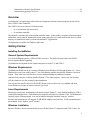
On the GM215 DIP Switch Settings pop-up window, select the Motion Control Mode tab.
•
Select the appropriate axis (X, Y, Z or W, in that order by device).
•
Check the Program Mode checkbox.
•
Select the NEMA motor frame size from the drop-down menu.
•
Set the physical DIP switches on the device to the settings shown in the window.
•
Repeat for other axes (if required).
The pop-up window should appear something like this:
3
Illustration 1
Note that DIP switches 6-10 are only used to set motor current in Motor Drive Mode. They are ignored
in Motion Control Mode; in this mode, the motor current is set dynamically using the CONFIGURE
command.
If only one device is used, it must be the X axis. Other devices must be assigned in the order Y, Z, W.
When the DIP switches for all devices are set, the next tasks are:
•
Daisy-chain all devices to the RS485 communications line (see GM215 Step Motor Drive
Manual).
•
Wire device I/Os if required.
•
Provide DC power to all devices.
•
Connect stepper motors (can be omitted for initial testing).
•
Attach RS485 adapter to PC via a USB cable (next section).
Programming Connector
Programming the GM215 devices requires an RS485 hardware interface. Most PCs do not come with
RS485. If anything, they have RS232, which is not compatible with the GM215 because RS232 is not
capable of multi-drop (multiple devices on a “party line”).
USB to RS485 adapters are commonly available, and one will be required for use with the GM215.
RS485 uses three wires:
•
Ground (common)
•
A (also known as Data+)
•
B (also known as Data-)
Unfortunately, the relation of A and B to Data is sometimes inverted. Try the X axis alone at first. If
no communication can be established, swap the A and B connections at the RS485 adapter and try
again.
4
Starting GeckoMotion
GeckoMotion is started via the Windows Start menu or, on Linux, by entering “gmotion” on the
command line (or using the window manager icon or menu as appropriate).
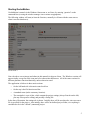
The following window will start (at least the first time; normally it will start with the same state as
when it was last shut down):
Illustration 2:
Note: the above screen image (and others in this manual) is taken on Linux. The Windows version will
appear similar, except for some icons and a few other minor differences. All of the same versions for
different platforms function identically, unless otherwise noted.
The application is laid out in three main sections:
•
On the left hand side is the main control tool-bar.
•
On the top is the file function tool-bar.
•
A standard menu (in the customary location).
•
The remainder is a set of tabs, which contain the project settings (always first tab on the left)
plus any files open for editing, and possibly a listing file.
In the above illustration, the settings tab is shown. Initially, there will be no other tabs, since no source
file is specified for the project. Also initially, there will be no defined project folder, so everything is
considered to be in the “default” (unnamed) project.
5
Creating a Project
It is recommended to always use a named project. GeckoMotion defines a “project” in relation to a
unique “project folder”. All settings and most project source files should be saved in the project folder.
To create a new project folder, make sure the Settings tab is selected in the main window.
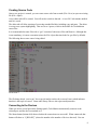
To the right of the Project Settings label, click the first icon (Create new Project). A folder creating
dialog will appear something like the following:
Illustration 3
Navigate to a suitable location (a base folder for all GeckoMotion projects) then enter the new project
name in the top field.
The “base folder” mentioned above is platform-dependent. On Linux, the default is
~/geckomotion/Projects, however you might have to manually create this folder if it does not exist. On
Windows, this directory will normally be something like
user\AppData\Local\Programs\geckomotion\projects, however the exact location depends on platform and
installation options.
Unless there is a good reason otherwise, it is recommended to place all project folders under this same
base folder.
The project folder will be created automatically when you hit the OK button. There is no need to use
the “Create Folder” button unless you want additional folder levels.
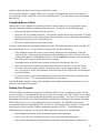
When you hit OK, the following window may appear:
6
Illustration 4:
You can safely ignore this error for now if it appears. It just indicates that the default RS485 device
node or COM port is not available.
After returning from the new folder selection, the Settings panel will be filled in with some values:
“Current”: this drop-down menu will contain the complete folder name of the new project. Other
projects will also be included in the menu (if any) in order of most recent use. You can quickly switch
between projects by selecting from this menu.
“Top Level Source”: this will be <none> for a new project, until you create or open a source file and
set it to top-level.
“Library search order”: this is a list of folders which the compiler will search when locating library
files. You can select a row of this list, and drag it around to re-order the search order. The “Defaults”
button will reset the entire list to the normal default, which is to search the project folder first, then user
then system-wide locations. You can hit the “Add” button to add a new folder to the list.
“Target”: this specifies the target device type. Currently, only GM215 is available.
“Log debug info” (or “Log all communications”): If ON, this logs all data sent between the application
and the devices to the logging window or console. You should only enable this if requested by
technical support, since it creates a continuous stream of messages in the log window.
“Serial Port”: This selects the appropriate USB or serial port. Since RS485 serial ports are basically
indistinguishable at the PC software level, you will see not only the RS485 adapter listed here, but also
the normal PC serial ports. On Linux the serial ports are listed using the contents of
/dev/serial/by-id.
If this does not locate the port (possibly on older Linux versions), then you can manually enter the
device node name e.g.
/dev/ttyUSB0
On Windows, serial ports are listed by traditional COMn name. Select one which is denoted a USB
port.
The serial port drop-down list is populated dynamically each time it is popped down. If there is any
confusion over which port to select, unplug the RS485 adapter from the USB, drop down the list, plug
it back in, then dropping down the list again should show a new entry.
7
Creating Source Code
Once a new project is created, you can create source code from scratch (File->New) or open an existing
file (File->Open).
A new editor tab will be created. You will need to switch to that tab. A “new file” tab remains untitled
until it is saved.
The editor tab will allow entering of text using standard facilities including copy and paste. The editor
is set up to use syntax highlighting. Tabs are set to 4 spaces, which is the default for GeckoMotion
source files.
It is recommended to name files with a “.gm” extension: both source files and libraries. Although this
is not mandatory, it is most convenient (since the File->Open function looks for .gm files by default).
The following shows some source being edited:
Illustration 5:
The file being edited, “test-io.gm”, has a special marker on the tab (a star on Linux) which indicates
that this is the top-level source. Some other library files are also open on adjacent tabs.
Connecting to the Devices
When you select a serial port on the Settings panel, GeckoMotion automatically connects to the
selected port, and the devices attached to it.
The Status button (bottom left) shows whether the connection was successful. When connected, that
button will show as “1 [READY]” (where the number is the number of devices detected). You can
8
press that button to see a more detailed display of device status. It looks something like the following:
Illustration 6:
In the above example, two devices (X and Y axes) are connected. Each device shows the input, output,
error status, position, velocity and whether the device is executing a command (busy).
If no devices are detected (for example because no serial port, or the wrong serial port, is selected) then
the Axis column will show all “-”.
The Log Window
When developing a GeckoMotion program, it is sometimes useful to be able to observe the
communication between the application and the devices. The log window, shown below, can be
displayed using View->Log. This shows not only the data communication, but also other messages
related to the operation of the GeckoMotion application.
Illustration 7
This example of the log window shows the typical messages which are output when the application is
9
started. In this case, there are two drives connected, X and Y.
The Auto Scroll button is a toggle. When active, the log will automatically scroll to keep the most
recent message visible. Otherwise, you need to manually scroll. The Clear button clears all messages
from the log.
Compiling Source Code
When all devices are connected, as shown by the above status window, you can compile the source
code into instructions which are understood by the devices. To do this, use the following steps:
•
Select the tab which contains the top-level source
•
Press the “Set Top” button (at top left). This tells the compiler which file to start with. This and
the previous step only need to be performed once for each new project; thereafter, GeckoMotion
remembers the top-level source for that project.
•
Press the Compile button (second from top left).
If all goes well, a green bar will appear in the source code. This indicates the next instruction that will
be executed by the devices. If you do not see the green bar, check the following:
•
There might be errors in the source code or library, which prevent compilation. If the edit
window is split, with messages in the bottom section, then there are errors. You can click on a
message line, and the corresponding source line will be highlighted in yellow. You can edit that
line (or any other code) to fix the error, then re-compile.
•
You might need to scroll the source window to bring the execution bar into view.
•
If the execution bar is not on the first instruction of the source, the devices may have been
executing a previous program, and the execution position is at an unexpected point. In this
case, you can press “Start” (first button in Control section) which will force the execution point
to the first location.
•
If you do not want to start at the beginning, you can put the edit cursor on any instruction line,
then press “GoCsr”. The execution bar should move to that point.
Once the program compiles without errors, and the execution bar is at the expected position, you can
proceed to run and test the program.
Testing Your Program
Note that unlike conventional compilers, GeckoMotion allows you to recompile at any time, and run
from any location. Just remember that the devices may be executing at an “old” location, so you might
need to use GoCsr to get to the appropriate point where you are testing. This saves a lot of time when
developing code, because you are not compelled to start from the beginning of the program each time.
When using GoCsr, try to avoid jumping directly into subroutines. If a RETURN instruction is
encountered without a corresponding CALL, the devices will not know where to return to, which will
cause incorrect code execution. Similar consideration applies to GOTO ... LOOP instructions.
When testing your program, you can use the following features (buttons on left hand side):
•
Start: abandon current test, and reset execution point to first instruction.
•
GoCsr: move the “next” location to execute, to the cursor line in the editor panel.
•
Step: execute the instruction with the green execution bar, and stop at the next instruction in
10
normal sequence.
•
Next: similar to Step, except stops on the next instruction in textual sequence. This means that
Next on a CALL instruction will execute all the way through the called subroutine, and only
stop when the subroutine returns. Similarly for GOTO...LOOP instructions, in which case the
remainder of the loop iterations is performed without stopping.
•
Run: continue executing until Stop is pressed, or a breakpoint is encountered. When running,
the execution point in the program is continually updated. If the device is executing a longrunning instruction, such as a move or wait, you can see which instruction is running.
•
Stop: stop execution of a Run (or Next) as soon as the devices complete the current instruction.
•
Breakpoint: sets a breakpoint at the edit cursor location. If there is already a breakpoint there, it
is cleared. Whenever the device is executing instructions, it will always stop before executing
an instruction with a breakpoint.
•
Clear All: clears out all current breakpoints.
When you edit code and recompile, usually any breakpoints you set (including those in libraries) will
remain on the same line. If you directly edit a line that has a breakpoint, then the breakpoint may be
shifted to an adjacent line, or you may end up with multiple breakpoints on a line. When you
recompile, this is all cleaned up, however you should confirm that breakpoints are on the expected
lines.
Writing Your Program to Device ROM
When satisfied with a program, you can “burn” that program to all attached devices. This means that
the program can be executed autonomously on the devices, without requiring a PC to be attached.
The program is written to the devices when the “Flash” button is pressed. This may take a few seconds
for a large program.
Running GM215 Devices Without a PC
After flashing, to actually run the devices in autonomous motion control mode, you need to:
•
Unpower the devices.
•
Disconnect the RS485 line from the PC (leaving only the RS485 interconnection between
devices).
•
Change DIP switch 2 to the ON position (this sets RUN mode), on all devices.
•
Re-power the devices.
Saving a Project
GeckoMotion always saves project settings as soon as you close the application, or switch to a different
project.
Any source code which is changed, but not yet saved, will cause a prompt to appear. You can then save
the source file(s).
11
GeckoMotion Reference
Application Layout and Windows
There is a single main application window, and a number of secondary windows. The main window is
always displayed, and the other windows are shown using various menu commands. You can use the
mouse to re-size and re-position all windows, and the positions and sizes will be remembered next time
the application is started.
From the main window, the secondary windows are displayed using the following commands:
•
Log: use menu command View->Log.
•
GM215 Device Status: use menu command View->Status, or you can press the device status
button at the bottom of the left-hand toolbar (the “info” icon).
•
GM215 Input Simulation/Overrides: use menu command View->Input Overrides, or press the
“input” button at the bottom of the left-hand toolbar.
•
DIP Switch settings: use menu command Help->DIP switch settings. This window is a quick
way of finding the correct switch settings on the drive hardware.
Menus and Toolbars
There are two toolbars: the top toolbar contains short-cuts for file editing operations, and the left
toolbar controls program compilation and execution. All of the toolbar buttons have a tool-tip defined,
which will be shown if you hover the mouse over the toolbar button.
The top toolbar buttons, from left to right listed as their menu equivalent, are:
•
File->New [Ctrl-N]: Create a new, blank, editor tab. When you select that tab, you can enter
new code. You will be prompted for a file name when saving that file.
•
File->Open [Ctrl-O]: Open an existing file in a new tab.
•
File->Save [Ctrl-S]: Save the current tab, if edited.
•
File->Save As: Save the current tab, giving the file a new name. This creates a copy of the
original file that was opened (if any). Any further edits on that tab apply to the new file.
•
Edit->Undo [Ctrl-Z]: Undoes the most recent edit on the current tab. There is an unlimited
number of undo levels.
•
Edit->Redo [Ctrl-Shift-Z]: Redoes the last edit that was undone.
•
Edit->Cut [Ctrl-X]: Cut currently selected text to clipboard.
•
Edit->Copy [Ctrl-C]: Copy currently selected text to clipboard.
•
Edit->Paste [Ctrl-V]: Paste clipboard to current cursor position.
•
Edit->Find [Ctrl-F]: Pop up window which allows searching and/or replacing text.
The left toolbar buttons, from top to bottom, are:
•
Source
•
Set Top [Ctrl-Shift-T]: Mark the current editor tab as being the “top-level” source file
for the project. This file will be the first source code compiled. The tab which is
currently selected as the top-level file (if any) is marked with a special icon in the tab.
12
•
Compile [F5]: Compile the top-level program file. This is necessary before the devices
can run the program. If any edits are made, you will need to recompile.
If compilation is successful, then an assembler listing tab will be created. This is a readonly tab, but you can switch to it and examine the binary code which was created. Note
that not all lines of source code will be shown in the listing. Only lines of code which
actually created binary object code will be shown in the listing.
•
Breakpoint [F2]: Set (or clear) a breakpoint at the cursor position in the current tab. If
successful, a breakpoint icon is inserted at the start of the text line containing the
instruction. If the cursor is not on a valid line of code, the breakpoint will not be set. If
there is already a breakpoint on the line, it will be cleared.
When executing code with breakpoints, execution will stop at the breakpoint before that line
of code is executed.
Note that breakpoints are not preserved across re-starts of the application.
•
•
Clear All [Ctrl-Shift-K]: Remove all breakpoints from the code.
Control
Most of these buttons are not enabled until the current project has compiled without errors.
•
Start [F4]: Move the execution point so that the first instruction of the program will be
executed next.
•
Go Csr [Ctrl-G]: Move the execution point to the instruction where the cursor is in the
current tab.
Be careful when directly moving the execution point using this command. If you move into
a subroutine, then the drives will not know the proper return address, so that when the
RETURN instruction is encountered, the drive will flag an error. In this case, you will
need to use EStop to reset all drives to a valid state.
•
•
Step [F8]: Execute the next instruction. If that instruction is a CALL, then the
execution point will be at the start of that subroutine.
•
Next [Ctrl-F8]: Execute the next instruction. If that instruction is a CALL, then the
entire subroutine will be executed before stopping at the instruction immediately
following the CALL.
•
Run [F9]: Execute instructions continuously, until Stop or Pause, or a breakpoint or
error is encountered. As the devices execute instructions, the green bar which shows the
instruction being executed will animate so that you can see which instructions are being
executed.
•
Stop [Ctrl-Q]: Stop at the end of the currently executing instruction, allowing it to
complete normally.
Device
•
Pause: This is a toggle button, which will temporarily halt execution of the current
instruction (if one is executing), or resume from a pause. If this is a motion command,
then the axes will decelerate to a stop while paused. Note that this functionality does not
work with the current device firmware.
•
Cancel: Cancel the current paused instruction. Note that this functionality does not
13
work with the current device firmware.
•
EStop [Ctrl-F12]: Reset all devices to location zero. Use this if an error is causing one
of the devices to lose synchronization.
•
Flash: Write the current program to all attached devices, for stand-alone execution. This
may take several seconds for large programs.
•
Connect: Connect or re-connect to the serial port defined for this project.
•
Status: This button changes its appearance depending on the connection state. Normally,
it will show “2 [READY]” where the initial digit is the number of connected devices.
READY means the devices are waiting for the next instruction. RUN means an
instruction is executing.
Pressing this button will display a more detailed status window.
•
Inputs: This pops up the Input Simulation/Override window. This window allows
simulation of the 3 input signals which are available to each drive. It is only possible to
activate the input signal, and the activation is ORed with the actual input signal (if any).
If the hardware is driving the input active, then it is not possible to force the input
inactive using this window.
Project and File Management
The Settings tab (always the left-most tab in the main window) is used to define project settings, as
well as open and create new projects.
In the GeckoMotion application, each project is defined as a unique file system folder. Each project
folder contains the settings for that project, as well as (usually) the source files that are unique to that
project. Library files may or may not reside in the project folder. Library files which are shared
between several projects are usually stored in a separate folder.
From top to bottom of the settings tab, the following functions are described:
•
Project Settings. This is a toolbar with the following buttons:
•
Create new project folder: This opens up a folder creation dialog. In this dialog, enter
the name of the project in the Name field. This will be used as the name of the project,
and a folder with the same name will be created. There is also a Create Folder button,
but this only needs to be used to create another level of folders, not the new project
folder itself.
•
Open project folder: This opens an existing project.
•
Close project: This closes the current project and opens the default project. It is
recommended not to use the default project, but create a new (named) project
immediately.
•
Current: This is a drop-down menu containing a list of the most recent projects, including the
current one, listed in order of time of last use. This is a convenient way to switch between the
most recently used projects.
•
Top-level source: Gives the complete file name of the current project's top-level source file.
•
Library search order: This list box allows definition of the order in which folders are searched
for library source. Each entry is either a folder name, or is one of the special symbols:
14
•
{project} – indicates the current project folder, used for library files which are unique to
the current project.
•
{userlib} – folder containing library source common to all current user's projects.
•
{stdlib} – folder containing system-wide and installation default libraries.
Currently, there are no installed libraries, however future versions of GeckoMotion may define some as
experience is accumulated.
You can change the order of library search by dragging rows of the table, however it is recommended
to at least keep the default ordering of project, userlib, stdlib.
•
Target: This menu button allows selection of the target device. Currently, there is only one
choice, which is GM215.
•
Log all communications: This toggle switch controls whether a detailed communication log
should be kept. Normally, this should be OFF to prevent filling the log with needless detail.
•
Serial port: This drop-down menu allows selection of the hardware communications port. This
should be selected as the port with the RS485 converter. Unfortunately, since RS485 converters
are indistinguishable from ordinary RS232 adapters, it is necessary to manually select the
correct port.
The menu is populated with the current list of ports as known by the system whenever the menu is
displayed. If you are not sure which port to select, physically unplug the USB port with the RS485
converter, show the list, plug it back in, show the list again, and select the port which appeared the
second time the list was displayed.
Writing Source Code: the Text Editor
Each editor tab (except for the settings and assembly listing tabs) is a full-featured text editor. The
editor accepts all the usual commands, including copy and paste. It is set up to use syntax highlighting.
The editor has the following settings:
•
Tabs are set to 4 spaces.
•
Line numbers are listed on the left hand side.
•
Break point markers (if any) are shown in the leftmost column (after the line numbers).
•
The current execution point, when running a program, is shown as a green highlight over the
entire line.
•
Compilation errors, which are identified with a particular source line, are shown as a yellow
highlight on the line, but only when the error message is selected. Compiler error messages
appear in a list panel at the bottom of the main window if the compiler detects any syntax or
other errors. Clicking on the error message shows the source location of the error.
GeckoMotion Source (.gm) Syntax
A GeckoMotion program is a sequence of instructions which is executed on one or more GM215
drives. Each instruction is coded on a single logical line. A logical line is a sequence of characters
terminated by a line-ending character appropriate for your PC platform, which is not immediately
preceded by a backslash (\) character. For example, on Windows this is a CR LF sequence. Simply
15
hitting the Enter key in the text editor terminates the line.
A logical line may extend over several visible lines, by ending the line with a backslash on all but the
last visible line. The following example shows this usage:
This is the first logical line
and this is the second logical line.
This \
is \
a single \
logical \
line
And, finally, this is the fourth logical line (but the 8th visible).
A GeckoMotion instruction consists of a number of keywords (also called opcodes) and optional
parameters. An instruction may also be a label. Labels are not actually executed, but they denote
points of the program which may be the target of a branch or call instruction.
In addition to labels and instructions, comments, whitespace and macro definitions may be included in
the code. Comments and whitespace are ignored. Macros provide instructions to GeckoMotion, but
only during compilation and never directly during program execution.
Comments
Comments are used to document the intention and meaning of the program, since the instructions
themselves are somewhat cryptic, particularly after coming back to code after a few days.
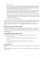
A comment is denoted by a semicolon (;) or pound/hash (#) punctuation character. The punctuation
and everything following, to the end of the line, is ignored by GeckoMotion.
Examples:
x+100, y-100 # Move diagonally to start position
z-10
; Z axis down
# Comment on its own line
Note: it is recommended to use the '#' character, since it is compatible with Python's comment
convention. A semicolon only works with GeckoMotion instructions.
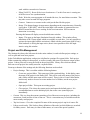
Whitespace
In general, whitespace (spaces and tabs) is ignored. The only exception is that the indentation of
instructions should line up. This restriction is because the Python parser is also used to process
GeckoMotion instructions, and Python has similar indentation restrictions. The following example
shows what is acceptable and what is not:
label:
x 100
y 200 # <- OK (but ugly)
next:
x 0
y 0
# <- this line will fail, because of mismatch in indentation
The general rule is to always “back out” any indentation so it lines up with some previous level of
indentation. In the above example, the “y 0” instruction did not line up with either the previous line, or
the “next:” label. Since the “next:” label was less indented than the “y 0” line, this indicates an
16
indentation error.
It is recommended to indent all instructions with a single tab character (or 4 spaces), except for labels
which are not indented. Macros have slightly different rules.
Macro Definitions
For additional programming flexibility, it is possible to define and use macros. A macro is not itself a
set of GM215 instructions, however it may be used to generate instructions, define program constants,
or perform arbitrary actions at compilation time. This is potentially an advanced feature, however there
are some simple use-cases which are valuable for writing maintainable and reasonably flexible code.
A macro is introduced by a triple open brace ({{{) mark, and ends with a matching triple close brace
(}}}). Inside these markers, you may write arbitrary Python code. The Python code will be executed
when the GeckoMotion compiler encounters them while scanning the source code. The brace markers
must appear on a line by themselves (with the possible exception of a '#' comment).
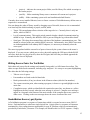
Here is a simple example showing how to define program constants:
{{{
x_start = 0
y_start = 0
x_size = 500
y_size = 950+2*x_size
}}}
draw_rect:
x {x_start}, y {y_start}
x+{x_size}
y+{y_size}
x-{x_size}
y-{y_size}
The macro definition (inside triple braces) defines four “constants”, which in this case define the
coordinates of the start of a rectangular motion, and the size of the rectange. The size of the y axis is
defined by a complex expression. The value of the constants is later used via the single-brace
expression evaluation. The term “constant” is a misnomer: in fact, these are all Python variables which
are being defined. It is possible that the values could be changed by a subsequent macro definition.
A macro definition may also provide a name for the macro. This name is only significant for
identifying the location of error messages. To name a macro definition, provide the alphanumeric name
after (and on the same line as) the open triple brace:
{{{ my_macro
# Python code...
inf = 1/0
}}}
The above example names the macro “my_macro”. A deliberate error is coded in the macro, namely a
division by zero. This would cause the compiler to halt with an exception when attempting to run this
macro. The macro name will assist with identifying the location of the error, which becomes more
important with complex code spread over several files.
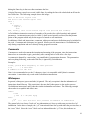
Simple Substitutions
The above example showed use of simple substitutions. Substitutions may be used in place of any
numeric parameter in a normal GM215 instruction. Substitutions are delimited by single brace
17
characters ({ and }). The content inside the braces is interpreted as a Python expression. This may be
arbitrarily complex, however it is recommended to limit these to simple mathematical expressions,
possibly involving constants, functions or variables defined in a previous macro definition.
Here is a slightly more complex example:
{{{
import math
radius = 10000
}}}
move_to_circumference_at_60_degrees:
x+{int(math.cos(math.pi/3) * radius)}, \
y+{int(math.sin(math.pi/3) * radius)}
Here, the macro uses the Python import directive to call in the mathematical functions module (don't
confuse this with the GeckoMotion import directive! Inside triple parentheses, everything is pure
Python). Subsequently, these functions can be used as operands to the MOVE instruction.
Note in the above example that floating point results must be explicitly cast to integer using int(). This
is a general rule: GM215 instructions that expect integer operands will not accept floating point values
returned by a substitution. You must ensure that integers are returned, otherwise the compiler will
signal an error.
Regarding the MOVE instruction in particular: the GM215 MOVE instruction has a relative and an
absolute form:
x+100
x-100
x 100
# <- relative form (move forward (CW) 100 steps)
# <- relative form (move backward (CCW) 100 steps)
# <- absolute form (move to location 100)
When used in conjunction with macro substitution, the +/- sign (for a relative move) must be outside
the braces. Otherwise, the move is always absolute, regardless of the sign of the macro substitution
result:
{{{
n = 100
nn = -100
}}}
x+{n}
x+{nn}
x-{nn}
x {n}
x {nn}
#
#
#
#
#
#
Move relative 100 CW
Move relative -100 CW (or 100 CCW)
Move relative -100 CCW (or 100 CW)
Move absolute to 100
Move absolute to -100. This is an error and will not
compile, since absolute moves must be non-negative.
Labels
Labels are recognized as a sequence of alphanumeric characters, followed by a colon. There should be
nothing following the colon on the logical line, except possibly whitespace and a comment. A label
must start with an alphabetic character (a-z or A-Z) or underscore (_). Subsequent characters may also
include digits (0-9).
Examples:
triangle:
Triangle:
# <- these are distinct labels.
Labels are case-sensitive.
18
_fooBar_:
alpha_987:
# All of the above labels equate to the same instruction address, since
# there are no instructions between them
goto elsewhere
# Uses of labels in instructions
hither:
call yon
Instructions
Instructions specify code to be executed at run-time. A single instruction specifies 1 to 4 program
locations. A total of 65,536 program locations are available in the GM215. If a program specifies
more than this many program locations, the code will not compile. Most instructions consume a single
program location, however the MOVE, HOME and JOG instructions will consume as many locations
as there are axes specified in that instruction.
It is recommended to indent the start of each instruction by a single tab, or four spaces. The instruction
must fit on a single logical line, and must not be followed on the same line by anything except an
optional comment or whitespace.
Available instructions and their syntax are listed in appendix A.
Library Import
Long programs may be separated into separate files. Each GeckoMotion project may have an arbitrary
number of source files. One of the source files is designated as the “top-level” source, by selecting its
editor tab then pressing the “Set Top” button. The top-level source is marked with a special icon on its
editor tab. Any source file in the project (or mentioned in the import directive) other than the top-level
source file is considered to be a “library file”.
Library files and top-level source files use identical syntax, and have exactly the same ability to specify
program code.
When the “Compile” button is pressed, GeckoMotion starts compiling the top-level source file. That
file may contain import directives. The import directive specifies a library file name and, when
encountered by the compiler, the compiler starts processing the specified file. At the end of the
imported library file, the compiler returns to the top-level source file, and continues processing it.
Library files may themselves contain import directives for yet other library files. The compiler
processes these in the same manner as for the top-level file.
Most import directives will use the “as name” clause. This creates a unique name-space for any labels
which are defined in the library file. Without this, a label in the library file which happens to be the
same as a label in the top-level source file will cause a compiler error. Using “as name” avoids any
such possible conflict.
Another difference between using “as name”, or not, is that the compiler handles generated code blocks
slightly differently. If “as name” is used, then code blocks are not emitted until the end of the top-level
source is reached. Otherwise, any instructions encountered in the library file are emitted at the point
where the import directive is encountered.
The typical use for a library, and the corresponding import directive, is to separate some commonly
used code into a single library file which can be re-used over several different projects. For example,
the initialization code for motor driver parameters (limit, configuration, etc.) is always the same for any
given hardware setup. It is thus simpler and less error-prone to put all such constant settings in (say) a
19
subroutine in a library file, then import the library file for each project which needs it.
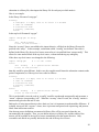
Here is an example:
In the library file named “setup.gm”:
xconfig:
x configure: 5.5 amps, idle at 71% after 2.5 seconds
x limit cw 12000000
x acceleration 8192
x velocity {1000*256}
return
In the top-level file named “top.gm”:
import “setup.gm” as setup
start:
call setup.xconfig
# rest of code follows...
Since the “as setup” clause was added to the import directive, all labels in the library file must be
prefixed with “setup.”. In this example, a subroutine called “xconfig” was defined. Since this is
defined in the library file, the top-level source must refer to it in qualified form “setup.xconfig”. This
allows for same-named labels in the top-level source, without introducing any ambiguity.
If the above top-level source was changed to the following:
import “setup.gm”
# <- no “as” clause
start:
call xconfig
# <- qualification removed
# rest of code follows...
then this would be quite different. In this case, the compiler would insert the subroutine contents at the
point of importation, as if the top-level was coded as follows:
xconfig:
x configure: 5.5 amps, idle at 71% after 2.5 seconds
x limit cw 12000000
x acceleration 8192
x velocity {1000*256}
return
start:
call xconfig
# <- qualification removed
# rest of code follows...
This is not desirable, since the code in “xconfig” would be run through unexpectedly and encounter a
“return” without a corresponding “call”. When the “as setup” clause is used, the “xconfig” routine is
automatically placed at the end of code.
Both styles of using import directives have their use, but it is important to understand the difference. If
in doubt, always use the “as name” clause, since it prevents unexpected code sequencing, and protects
labels from inadvertent conflict.
Note that any macro definitions encountered in library files will be processed when they are
encountered by the compiler. Thus, you can define macros in a library file, and the results of the
macros will be available in the top-level source immediately after the import directive. Only
executable code blocks are possibly deferred to the end of the top-level source.
20
Standard Library Folders
When an import directive is encountered by the compiler, it searches for the specified library file in a
number of standard folders. The folders, and their search order, may be specified in the project
settings. By default, the order of search is:
•
The project folder for the current project,
•
The user-specific standard library folder,
•
The system-wide standard folder.
Except for the project folder, the actual location of the standard library folders is platform-dependent.
As a general rule, create new libraries in the project folder if the library is specific to just that project.
If the library becomes more general, and would be useful for multiple projects, it may be moved to the
user or system folder. To do this, use your normal operating system services to move the file, or you
can use “File->SaveAs” followed by deletion of the original.
Standard Libraries
The following library should be imported at the top of the top-level source:
import “usrlib.gm”
This library does not generate any GM215 code, but it contains some basic macro definitions that are
assumed to exist by other libraries, and are useful in generating code in a maintainable and flexible
manner.
Note that this is one exception to the general rule that import directives should use the “as name”
clause. Since usrlib.gm does not generate any code or labels, but only macros, there is no need to use
“as name”.
Future releases of the GeckoMotion application may provide more standard libraries as experience is
gained.
Instruction Set
For a detailed description of the GeckoMotion instruction set, refer to the GM215 Instruction Set
Manual.
Appendix A: Instruction Syntax
This appendix defines the syntax to be used when writing GM215 instructions.
General Rules and Instruction Parts
The general form of an instruction is:
[axis] [opcode] [parameter-clause...] [comment]
An instruction must be coded on a single logical line. It may be prefixed with white space (a single tab
or 4 spaces is recommended). All components are optional, except that at least one must be given.
[axis]
Some instructions target a single axis. In this case, the axis specification defines the target axis.
21
Otherwise, the axis is not specified and the instruction applies to all attached axes.
The axis is specified as X,Y,Z or W, or their lowercase equivalents.
[opcode]
All instructions specify an opcode, except for the MOVE instruction, where the MOVE opcode is
implicit.
Opcodes are one of the defined set of keywords. These are not case sensitive, so LIMIT, Limit and
limit all mean the same thing. Some opcodes are multiple word (like ZERO OFFSET). In this case,
any whitespace may be used to separate the words.
The defined opcodes (with allowed abbreviations and alternatives) are:
Keyword
CONFIGURE
ACCELERATION
VELOCITY
ANALOG INPUTS TO
VECTOR AXIS IS
MOVING AVERAGE
LIMIT CW
POSITION ADJUST +/ZERO OFFSET
MOVE
HOME
JOG
SPEED CONTROL
GOTO
CALL
RETURN
IF
WAIT
OUT
Abbreviation/Alternative
CONFIG
ACCEL
VEL
Requires axis
yes
yes
yes
VECTOR AXES ARE
yes
POSITION ADJ +/OFFSET
<may be omitted, implied>
yes
yes
yes
yes
RET
yes
[parameter-clause...]
Instruction parameters are generally numbers, some with additional punctuation and parameter
keywords. These are listed with each individual instruction. Instructions take zero or more parameters.
[comment]
Any instruction may contain a '#' (recommended) or ';' style comment. The start of a comment, or the
end of logical line, terminates the preceding instruction on that line (if any).
Instruction List
The following list defines all the instructions currently accepted by GeckoMotion. Some of the
characters in the definition are not to be included literally; they are used to clarify the syntax. These
metacharacters are:
[]
Brackets: indicate contents are optional
22
...
Ellipsis: previous syntactic element may be repeated zero or more times
|
Vertical bar: separates alternatives. Only one of the alternatives may be used.
italics A syntax variable construct. For example decimal indicates a decimal unsigned integer.
Any other punctuation characters are literal.
Syntax Variables
decimal<range>
An unsigned decimal (for example 123) or a macro substitution equating to an integer (possibly
negative). <range> specifies the allowable numeric range for the parameter.
integer<range>
A signed or unsigned decimal (for example -20, 10000, +200000) or a macro substitution equating to
an integer
float<range>
Floating point number (for example 3.14, -42.01) or a macro substitution equating to a floating point
value.
axis
Axis identifier: X|Y|Z|W (or lower case)
label
Label destination.
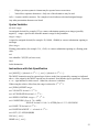
Instructions with Axis Specification
axis [MOVE] [+|-]decimal<0..224-1> [ , axis [+|-]decimal<0..224-1> ]...
The MOVE instruction may be repeated up to 4 times on the line (separated by commas) as indicated
above. Also, uniquely, the MOVE opcode may be omitted. Note that the sign is significant. If present,
a + or – sign indicates a relative move. Otherwise, the move is absolute.
When using the relative offset form, the range is reduced to -223..223 -1.
axis [ZERO] OFFSET integer
axis VELOCITY decimal<1..223-1>
axis ACCELERATION decimal<1..223-1>
axis SPEED CONTROL integer<-223 ..223-1>
axis CONFIGURE: float<0..7.0> AMPS ,
IDLE AT decimal<0..100> % AFTER float<0..25.5> SECONDS
axis LIMIT CW decimal<0..224-1>
axis POSITION ADJUST + / - decimal<0..215-1>
axis OUT 1|2|3 OFF|ON|BR|RS
JOG axis [ , axis ]...
HOME axis [ , axis ]...
23
Instructions Applying to All Axes
GOTO label [ , LOOP decimal<0..255> TIMES ]
CALL label
RETURN
IF axis IN1|IN2|IN3|RDY|ERR IS OFF|ON GOTO label
WAIT float<0..65.535> SECONDS
MOVING AVERAGE [ axis [ , axis ]... ] decimal<1..127> SAMPLES
ANALOG INPUTS TO [ axis [ , axis ]... ]
VECTOR AXIS|AXES IS|ARE [ axis [ , axis ]... ]
24