1
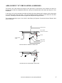
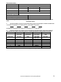
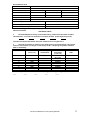
DD
Rev-Low
Maintenance Manual
___________________________
Spring Air Systems Inc., Oakville, Ontario
Phone (866-874-4505), Fax (905) 338-0179, [email protected]
2010 Update
DD REV-LOW Maintenance and Operating Manual
Table of Contents
Introduction
Spring Air Systems Hood Model Number Designations
Principle of Operation
Variflow Baffles
Baffle Settings
Arrangement “D” Fire Damper Assemblies
Adjusting the Fire Damper Blade Position
RevLow Maintenance Instruction
Cleaning the Exterior
Adjusting the Fire Damper Blade Position
Trouble Shooting
Measuring the Exhaust Airflow
Installing the Terminator Baffles
Measuring the Supply Airflow – MB models only
Measuring the Supply Airflow – MJ models only
Startup Report
1
1
2
3
3
4
6
7
8
8
8
9
10
11
13
14
INTRODUCTION
Thank you for selecting a SPRING AIR SYSTEMS INC. Commercial kitchen exhaust Rev-Low dry extractor.
Your system consists of a dry extractor, exhaust fan and on/off switch or control panel. Others manufacturers
may have supplied the exhaust fan and on/off operator.
Your SPRING AIR SYSTEMS INC. Dry extractor model was selected to best meet the design requirements of
your commercial kitchen application.
The DD series dry ventilator is a UL/ULC listed “Exhaust Hood with Exhaust Fire Damper”.
Typical SPRING AIR SYSTEMS Dry Rev-Low Ventilator Installation
An ON/OFF selector switch or touchscreen located in the kitchen area or mounted on the exhaust fan starter
coil electrical enclosure normally controls the exhaust fan.
SPRING AIR SYSTEMS HOOD MODEL NUMBER DESIGNATIONS
There are numerous types and styles of SPRING AIR SYSTEM Rev-Low ventilator available. Refer to the
UL/ULC label for the complete model number and exhaust flow requirement for your dry ventilator. The UL/ULC
label is located on the underside of the grease through on the right hand side of the dry ventilator.
SPRING AIR SYSTEMS HOOD MODEL NUMBER DESIGNATIONS
D
C
H
D
Cold water spray/hot water wash
Hot water wash
Dry grease extractor
T
F
D
Thermostatic Fire Damper
Fusible link, spring loaded fire damper
Fusible link, dead weight fire damper
S
B
BS
DB
Shelf type hood
Box type hood
Box shelf type hood
Double box type hood
MG
MP
MI
MB
MJ
F
Make up air through front grilles
Make up air through perforated panels
Make up air internally
DynaFlow Tri-Zone control system
DynaFlow perimeter defense system
Single row canopy finished on all sides, Rev-Low
10
4
The length of the ventilator in feet
The width of the ventilator in feet
Model Number Designation - Ventilators
Chart No1
D
DN-RevLow Maintenance and Operating Manual
B
F
10
4
1
PRINCIPLE OF OPERATION
A commercial kitchen cooking line consists of many different appliances depending on the type of restaurant or
institution. In every commercial kitchen the cooking
Exhaust Air
vapors that comprise of grease, smoke, and products
of combustion rise off the cooking surface. Natural
Roof of hood
convection forces drive the cooking vapors up towards
Core Extractor
the back wall as shown in figure 2. The kitchen dilution
Variflow baffle
Back wall of hood
air is entrained into the cooking vapors and the air
Optional 3" aiir space
Front of hood
mixture generally follows the profile of the back and
top of the hood. The mixture of grease, smoke,
Kitchen dilution air
products of combustion, lint, dirt and kitchen dilution
air proceed along the roof of the hood and follow a
Vapours from appliances
path down towards the core extractor slot (the core
extractor slot extends along the length of the hood).
Most of the air mixture enters the slot and a small
APPLIANCES
amount rolls back into the hood canopy to meet the
main air stream again.
The REV LOW Hood Model DD-B-F
Figure 2
Optimizing the amount of air mixture that enters the core extractor slot is the key to the RevLow design. The
RevLow hood must incrementally maximize the amount of the air mixture that enters the slot and minimize the
amount of roll back into the canopy as the total amount of the air mixture deviates along the length of the
cooking lineup.
VARIFLOW BAFFLES
Exhaust duct collar
Top of core extractor
End mullion
Front of core extractor
Variflow Baffle
Shown in full open position
Core extractor slot
Removable Inserts
Grease trough
Core extractor slot
Section View of Core Extractor for DD-B-F Revlow Hood
Figure 3
The RevLow accomplishes this complicated process with a unique core extractor profile that contains a series of
specially designed variflow baffles located along length of the core extractor. See Figure 3 above. The variflow
baffles are adjusted prior to shipment to allow the optimum amount of the air mixture to enter the core extractor
slot and thereby minimize roll back into the hood canopy. For instance the variflow baffles located above a
Charbroiler are opened to the maximum 450 CFM/ft position and the variflow baffles located above ovens or
steamers are closed to the minimum 90 CFM/ft position. This variable adjustment along the length of each hood
provides an exhaust system that truly minimizes the amount of exhaust air to properly ventilate any kitchen line
up.
DN-RevLow Maintenance and Operating Manual
2
VARIFLOW BAFFLE SETTINGS
Variflow Baffle labeling
Figure 5
Each baffle is assigned a setting based on the type of appliance under the hood.
Roof of hood
Exhaust duct collar
Core extractor
Variflow Baffle
Back Wall
Back of hood
Front of hood
Drain connection
Baffle Closed
Baffle Partially Closed
Baffle Opened
Section View of RevLow Extractor with Detail of Variflow Baffle
Figure 4
DN-RevLow Maintenance and Operating Manual
3
ARRANGMENT “D” FIRE DAMPER ASSEMBLIES
The section view of the exhaust fire damper to the right shows a cross section of the exhaust duct collar, fire
damper blade, fusible link, adjustable cable block, spring, and stainless steel cable when the damper is in the
set position.
In the event of a fire in the exhaust duct collar the fusible link melts releasing the fire damper, which closes tight
on the damper blade stops and seals. The second drawing shows the damper as the fusible link has been
removed. The damper will rotate clockwise against the damper bar weight and close.
The complete assembly is part of the UL/ULC listed Spring Air Systems “Commercial Kitchen Exhaust Hood
with Fire Damper”.
DAMPER BLADE
DUCT FLANGE
DAMPER BLADE STOPS
SPRING
DAMPER BLADE
STOPS
CABLE BLOCK
FUSIBLE LINK
PIN
SECTION VIEW OF ASSEMBLE FUSIBLE LINK
SECTION VIEW OF DISASSEMBLE FUSIBLE LINK
DN-RevLow Maintenance and Operating Manual
4
UP TO 18"
PIN
WIDTH
FIRE DAMPER
BLADE
FIRE DAMPER
SHAFT
EXHAUST DUCT
COLLAR PERIMETER
OVER 18" UP TO 32"
PIN
PIN
FIRE DAMPER
BLADE
WIDTH
FIRE DAMPER
SHAFT
EXHAUST DUCT
COLLAR PERIMETER
SPRING
DAMPERS OVER 32"
PIN
PIN
PIN
FIRE DAMPER
BLADE
WIDTH
EXHAUST DUCT
COLLAR PERIMETER
SPRING
SPRING
FIRE DAMPER
SHAFT
UNDERSIDE OF TOP OF HOOD
LEGEND
CABLE BLOCK
FUSIBLE LINK
S/S FUSIBLE LINK CABLE
PIN WELDED TO FIRE DAMPER BLADE
SPRING WELDED TO DUCT COLLAR
DN-RevLow Maintenance and Operating Manual
5
ADJUSTING THE FIRE DAMPER BLADE POSITION:
The fire damper fusible links, springs and cable blocks are all accessible through the front on the hood. For dry
extractors and cartridge remove the inserts near the center of the hood.
Remove the insert
DRY EXTRACTOR INSERT IN PLACE
DRY EXTRACTOR INSERT IN REMOVE
The blade position is adjusted by removing the fusible link/cable and block assembly from the damper pin. The
fire damper will close and the complete assembly will hang loose from the spring. Loosen the set-screw on the
adjustable block and pull the stainless steel cable through the block to open the damper or release cable from
the stainless steel block to close the fire damper. Once the correct position is reached, re-tighten the set screw
on the adjustable block and re-ached the fusible links on the damper pins.
The single fusible link damper has one block to adjust.
Single Fusible link Damper
The double fusible link damper has two blocks to just and the three fusible link damper has up to four blocks to
adjust.
Two fusible link Damper
DN-RevLow Maintenance and Operating Manual
6
REVLOW MAINTENANCE INSTRUCTIONS
Hood with Spring Air Systems RPD Controller {TruFlow Control Panel}
At the start of the day
1. Rotate the occupied/Unoccupied switch to the occupied position to start the exhaust system {Touch the fan
on/off icon on the Power window if system is not setup on automatic start/stop schedule}. The exhaust fan(s)
will turn on and after a minute time delay the supply unit(s) will turn on.
2. Check each hood for air movement in the slot. Put your hand up to the entrance of the slot and feel if there
is air movement. The air movement should feel the strongest over the heavy appliances. (broilers)
Check Air Flow in slot
3. If there is no air movement check if the green fan light on the Spring Air remote panel is on (If not check the
breaker panel or fuse), check if the motor starters have pulled in (Press the red reset button), and finally check
fan belts in exhaust fan(s) on the roof. {TruFlow systems – check Operation Status window for messages}. If
necessary, call a service technician.
4. Go to the makeup air diffusers and check for air movement from the supply unit. If no air movement check,
motor starter (push red reset button), check fan belts on unit on roof. {TruFlow systems – check Operation
Status window for messages}. If necessary, call a service technician.
5. Check that all the grease inserts are in the hoods and installed properly.
At the end of the day
1. After the cooking equipment has been turned off rotate the occupied/Unoccupied switch to the unoccupied
position to shut off the exhaust system. {Touch the fan on/off icon on the Power window if system is not setup
on automatic start/stop schedule} The exhaust and supply fan(s) will shut down.
2. The RevLow hood will deposit particulate on both the hood backwall and roof. Wipe down the stainless
steel backwall above the appliances and the interior of the hood, including the back and roof. Use a recognized
hood degreaser. Wipe down the underside of the grease trough. This is located directly above the cooks’ head.
Wipe Interior of Hood
Empty Grease Cup
Steam Clean Interior
At the end of every other cooking day
1. Empty the grease cups located under the grease trough.
2. Remove the grease inserts and wash in a dishwasher or pot sink. . Use a recognized hood degreaser and
clean to bare metal.
3. Replace the insert in the hood.
DN-RevLow Maintenance and Operating Manual
7
At the end of the cooking day every six months
1. After removing the grease inserts for cleaning check the position of the Variflow Baffles in the hood. The
Variflow Baffles should be open over the heavy equipment and closed over the lighter equipment. (Baffles
should be wide open over charbroilers and closed over ovens.
2. Steam clean the interior of the grease extractor
3. Go to the roof and check the condition of the exhaust fan and makeup air fan belts. Tighten or replace as
necessary.
4. Replace the makeup air filters. (Filter replacement times will vary with location of the restaurant).
Inspect Baffle Positions
Check Baffle Setting
CLEANING THE EXTERIOR
Normal soil can be removed with a mild detergent and water mixture applied to a cloth. To remove baked on
grease, apply a cleanser to a damp cloth or sponge and rub on the metal in the direction of the polishing lines.
DO NOT RUB IN A CIRCULAR MOTION.
Burnt deposits, which do not respond, can usually be removed by rubbing the surface with a SCOTCH-BRITE
scouring pad of STAINLESS scouring pads. DO NOT USE ORDINARY STEEL WOOL.
Heat tint can be removed by a vigorous scouring in the direction of the polish lines using a SCOTCH BRITE of
STAINLESS scouring pad in conjunction with a powdered cleanser.
TROUBLE SHOOTING
Low air
(i)
(ii)
(iii)
(iv)
(iv)
Improper exhaust fan rotation.
Broken or slipping belt.
Exhaust ductwork inspection door open.
Obstruction in the ductwork.
Flow-flow baffle must be adjusted
No Air
(i)
(ii)
(iii)
(iv)
(v)
(vi)
Broken belt.
Exhaust fan overload tripped.
Exhaust fan disconnect open.
Exhaust fan motor fuse blown.
Fire damper closed.
Check if baffles are upside down in extractor.
DN-RevLow Maintenance and Operating Manual
8
MEASURING THE EXHAUST AIRFLOW
The exhaust air is measured along the inlet slot of the ventilator. To ensure accurate results take a reading
every foot along the length of the ventilator is recommended.
PITOT TUBE OR ANEMOMETER
VANAXIAL VELOMETER
Hold the instrument perpendicular to the
VORTEX BAFFLE and parallel to the throat
(inlet slot) of the ventilator. Velometer should
not exceed three inches in diameter. Take
one measurement per insert
Hold the instrument perpendicular to the
VORTEX BAFFLE and parallel to the throat (inlet
slot) of the ventilator. Take three readings
across the throat and average the results per
insert
Calculating the Exhaust Air
Calculate the average velocity across the inlet slot and refer to the chart below for the corresponding CFM/ft
(l/s/m).
Ventilator Type
Velocity
Exhaust Air Volume
DD-B-F/DD-DI
DD-B-F/DD-DI
DD-B-F/DD-DI
DD-B-F/DD-DI
DD-B-F/DD-DI
DD-B-F/DD-DI
DD-B-F/DD-DI
DD-B-F/DD-DI
DD-B-F/DD-DI
DD-B-F/DD-DI
Fpm
m/s
CFM/ft
l/s/m
450
675
900
1125
1350
1575
1800
2000
2250
2450
2.3
3.4
4.6
5.7
6.9
8.0
9.2
10.2
11.5
12.5
100
150
200
250
300
350
400
450
500
550
140
210
275
340
410
480
550
620
690
755
DN-RevLow Maintenance and Operating Manual
9
INSTALLING THE TERMINATOR BAFFLE
The TBDD Terminator baffle is available in various lengths to suit adverse site conditions. This will
provide additional exhaust air over heavy appliances that are being effected by the surrounding
environment.
Installation:
Remove the TBDD from the packing material. Take off all of the Removable Access Doors “A” from the hood.
You should be able to clearly see all the adjustable baffles “B” and their settings. Ensure that the adjustable
baffle(s) “B” over the heavy appliance is set at 5, or 3 if the baffle is directly beneath the exhaust duct collar.
The TBDD baffles “C” are going to be installed on the adjustable baffles “B” over the light appliances. To install
the TBDD baffle “C” onto the adjustable baffle “B” simply line up the gap on the TBDD baffle “C” with the lower
end of baffle “B”. Tap the TBBD along the length until it is snug on baffle “B”. If the fit is loose remove the
TBBD baffle “C” and gently tap the gap with a hammer in the middle and at each end. Re-attach to baffle “B”.
Install these baffles on the two adjustable baffles “B” located on the right or left side of the charbroiler (when looking from
the front of the hood).
DN-RevLow Maintenance and Operating Manual
10
MEASURING THE SUPPLY AIRFLOW - MB
Measuring the total supply fan airflow through the Blade:
_____1.
Remove Blade front discharge perforated panel with appropriate tools.
_____2.
Turn Blade’s threaded rod counter-clockwise until the Blade comes to a fully open position,
which is required to determine the total supply volume at each hood.
_____3.
Turn supply fan on.
_____4.
Re-install Blade front discharge perforated plate with appropriate tools.
_____5.
Take velocity reading across the perforated plate as shown in the diagram below. Take two
vertical readings, one at 2” from the bottom of perforation and one at 4”. Repeat these horizontal
readings every 12” along the hood.
_____6.
Total all readings and divide by the number of reading to determine the average velocity.
_____7.
Multiply the average velocity x 72 x length of perforated panel (in inches) to determine the
total CFM per perforated panel. (It is critical to take the velocity readings 1” off the surface of the
perforated panel to use this formula).
_____8.
If the total supply volume was not correct and Spring Air Systems provided the supply
fan/unit then adjust the supply volume at the fan/unit or at field supplied balancing dampers. If the
supply fan/unit was not provided by Spring Air Systems advise the general contractor to adjust the
supply air volume and do not proceed unit the volume has been correct. The total supply volume
required can be found on the Spring Air Systems shop drawings.
DD-RevLow Maintenance and Operating Manual
11
Measuring supply airflow through the Custom Comfort Dial:
_____1.
Remove Blade front discharge perforated panel with appropriate tools.
_____2.
Turn Blade’s threaded rod clockwise until the blade is 1.5 inches off the vertical front surface
of the hood. See diagram below.
_____3.
Set the velometer parallel to the bottom discharge with the face open perpendicular to the
perforated screen where the air discharges and take a reading every 12” apart for the full length of
the hood. See diagram below.
_____4.
Total all velocity readings and divide by the number of reading to determine the average
velocity.
_____5.
Refer to Custom Comfort Dial Velocity Chart below. Based on the hood length and the
temperature rating indicated on the UL/ULC plate determine the Custom Comfort Dial Velocity.
_____6.
If the measured average velocity is too high, turn the Blade threaded rod counter-clockwise
5 times. Re-measure average velocity. Repeat until the measured velocity at Custom Comfort Dial is
correct.
_____7. If the measured average velocity is too low, turn the Blade threaded rod clockwise 5 times.
Re-measure average velocity. Repeat until the measured velocity of Custom Comfort Dial is correct.
FN or FB Hood Custom Comfort Dial Velocity Chart
Hood
Length
(ft)
CCD VELOCITY (fpm)
Heavy - Charbroiler
Heavy - Charbroiler
Heavy - Charbroiler
Heavy - Charbroiler
6000 F
6000 F
6000 F
6000 F
9 - 14
6-9
4-6
Up to 4
Set point
500
500
550
550
SIDE
FLOW
Set point
450
450
450
450
Medium – Griddle, fryer
Medium – Griddle, fryer
Medium – Griddle, fryer
Medium – Griddle, fryer
4000 F
4000 F
4000 F
4000 F
9 - 14
6-9
4-6
Up to 4
450
450
450
450
400
400
450
450
APPLIANCES
TEMP.
FRONT
DD-RevLow Maintenance and Operating Manual
12
MEASURING THE SUPPLY AIRFLOW – MJ
The supply air is measured along the bottom inside discharge opening of the make up air plenum. To
ensure accurate results take a reading every one foot along the length of the ventilator.
Measure supply air flow through comfort dial:
_____1.
Ensure the MJ blowers are powered when the exhaust fan is activated.
_____2.
Locate the rheostat on the back of the MJ Blower which is on top of the MJ plenum.
_____3.
Turn the rheostat 120 degree clock-wise to activate the MJ blower.
_____4.
Set the velometer parallel to the bottom discharge with the face open perpendicular to the
perforated screen where the air discharges and take a reading every 12” apart for the full length of
the hood. The first reading should be one inch from the end and continue every twelve inches to the
opposite end of the ventilator.
_____5.
Total all velocity readings and divide by the number of readings to determine the average
velocity.
_____6.
Refer to Custom Comfort Dial Velocity Chart below. Based on the hood length and the hood
temperature rating indicated on the UL/ULC plate determine the Custom Comfort Dial velocity on the
chart.
_____7.
If the measured average velocity is not correct adjust the rheostat as follows: Rotate
clockwise for lower or counterclockwise for higher velocity. Retake the velocity reading to confirm
the recommended set point.
FN or FB Hood
Custom Comfort Dial Velocity Chart
Hood
Length
(ft)
CCD VELOCITY (fpm)
Heavy - Charbroiler
Heavy - Charbroiler
Heavy - Charbroiler
Heavy - Charbroiler
6000 F
6000 F
6000 F
6000 F
9 - 14
6-9
4-6
Up to 4
Set point
500
500
550
550
SIDE
FLOW
Set point
450
450
450
450
Medium – Griddle, fryer
Medium – Griddle, fryer
Medium – Griddle, fryer
Medium – Griddle, fryer
4000 F
4000 F
4000 F
4000 F
9 - 14
6-9
4-6
Up to 4
450
450
450
450
400
400
450
450
APPLIANCES
TEMP.
FRONT
DD-RevLow Maintenance and Operating Manual
13
REV-LOW- STARTUP
REPORT
Project Name
Project Number
Date
Customer
Site Contact
Site Phone Number
Site Address
Your startup package from Spring Air Systems should include:
Description
YES
Complete set of drawings
X
Appliance lineup under each hood
X
Operating and Maintenance manuals
X
Three (3) TBH, terminator baffles per hood
X
NO
TECHNICIAN TO COMPLETE ALL HIGHLIGHTED SECTIONS
After arriving at site:
Description
YES
NO
Inspect the hoods for damage (if yes add description below)
Remove the inserts and check the internal adjustable baffle settings for each hood
and correct as required to match the drawings.
Check that all inserts are properly in place in each hood
Check that each exhaust duct collar is free and clear.
For DD hoods with fire dampers check that each fire damper operates freely and is
set in the open position.
Check the actual site appliance layout (SIZE AND LOCATION OF APPLIANCES)
against the appliance layout received for each hood in the startup package. If the
appliance layout is different contact Spring Air head office at 1-866-874-4505 for
revised baffle settings.
Check that the cooking appliances are pushed all the way back against the wall, or
as far back as possible. If front edge is closer that 9” to hood front, contact Spring
Air head office from site.
Check if there is a high shelf over any of the appliances. Note which appliance.
Turn off the all appliances under the hood(s)
Check the mounting height of lower front edge of each hood to finished floor
(inches)
Damage details:
DD-RevLow Maintenance and Operating Manual
14
Exhaust and Supply fan Information
Description
Please Fill In
Exhaust fan manufacturer
Exhaust fan model number
Exhaust fan motor horsepower
Exhaust fan voltage
Exhaust fan max FLA
Exhaust fan operating amperage / leg
1)
2)
3)
Supply fan manufacturer
Supply fan model number
Supply fan motor horsepower
Supply fan voltage
Description.
YES
NO
Turn on the exhaust fan
Turn on the supply fan
Check that the kitchen is under a negative pressure. Stand in the kitchen doorway
and air should be felt moving into the kitchen from the adjacent space.
INSERT POSTION IN HOOD
Baffle Adjustment
HANDLE IS UP AND OUT
CORRECT
UP SIDE DOWN
Measuring the Exhaust Volume at the Revlow Hood
The exhaust air is measured along the inlet slot of the ventilator. To ensure accurate results take a reading every foot
along the length of the ventilator is recommended.
VANAXIAL VELOMETER
PITOT TUBE OR ANEMOMETER
Hold the instrument perpendicular to the
VORTEX BAFFLE and parallel to the throat
(inlet slot) of the ventilator. Velometer should
not exceed three inches in diameter. Take
one measurement per insert
Hold the instrument perpendicular to the
VORTEX BAFFLE and parallel to the throat (inlet
slot) of the ventilator. Take three readings
across the throat and average the results per
insert
DD-RevLow Maintenance and Operating Manual
15
Revlow Exhaust Hood
Hood Item No.
Hood Model No.
Hood Length (inches)
Hood Width (inches)
No. of Baffles
Baffle Size (inches)
No. of 16” Inserts
No. of 20” inserts
Design Exhaust Volume.
Design Supply Volume.
Right overhang (wall/hood/open)
Left overhang (wall/hood/open)
Front overhand (front of appliance to front of hood)
1.
Confirm appliance lineup. Call Spring Air Systems, 1-866-874-4505 x 28, immediately if different from
below:
APPLIANCE LINEUP
2.
Set Variflow Baffles to factory recommended setting. Install Terminator baffle on baffles indicated with a
* on hoods with Charbroiler on common duct/fan. (Left to Right facing hood):
The baffle directly beneath exhaust duct collar should be set to no higher than 3.
3.
Calculate the exhaust air volume for each hood following the formula below. If the exhaust volume is
more than 5% over design or under design AT ALL, call Spring Air Systems 1-866-874-4505 x 2 immediately.
1
2
3
4
5
Insert No.
Insert Size
Velocity
Size correction
Exhaust Volume
(circle one)
measurement
factor (SCF)
CFM
(circle one)
Left to right
16” or 20”
(fpm)
16” = 0.29
fpm x SCF
20” = 0.37
1
16/20
0.29/0.37
2
16/20
0.29/0.37
3
16/20
0.29/0.37
4
16/20
0.29/0.37
5
16/20
0.29/0.37
6
16/20
0.29/0.37
7
16/20
0.29/0.37
Total CFM (add column 5)
4.
If adjusted, record FINAL variflow baffle settings (Left to Right facing hood)
____
____
____
____
____
DD-RevLow Maintenance and Operating Manual
16
Revlow Exhaust Hood
Hood Item No.
Hood Model No.
Hood Length (inches)
Hood Width (inches)
No. of Baffles
Baffle Size (inches)
No. of 16” Inserts
No. of 20” inserts
Design Exhaust Volume.
Design Supply Volume.
Right overhang (wall/hood/open)
Left overhang (wall/hood/open)
Front overhand (front of appliance to front of hood)
1.
Confirm appliance lineup. Call Spring Air Systems, 1-866-874-4505 x 28, immediately if
different from below:
APPLIANCE LINEUP
2.
Set Variflow Baffles to factory recommended setting. Install Terminator baffle on baffles
indicated with a * on hoods with Charbroiler on common duct/fan. (Left to Right facing hood):
The baffle directly beneath exhaust duct collar should be set to no higher than 3.
3.
Calculate the exhaust air volume for each hood following the formula below. If the exhaust
volume is more than 5% over design or under design AT ALL, call Spring Air Systems 1-866-8744505 x 2 immediately.
1
2
3
4
5
Insert No.
Insert Size
Velocity
Size correction
Exhaust Volume
(circle one)
measurement
factor (SCF)
CFM
(circle one)
Left to right
16” or 20”
(fpm)
16” = 0.29
fpm x SCF
20” = 0.37
1
16/20
0.29/0.37
2
16/20
0.29/0.37
3
16/20
0.29/0.37
4
16/20
0.29/0.37
5
16/20
0.29/0.37
6
16/20
0.29/0.37
7
16/20
0.29/0.37
Total CFM (add column 5)
4.
If adjusted, record FINAL variflow baffle settings (Left to Right facing hood)
____
____
____
____
____
DD-RevLow Maintenance and Operating Manual
17
Check for Drafts
1.
Turn on appliances.
2.
Spray cooking oil on the front right of Charbroiler (or what other appliance?).
Observe the smoke pattern and record which insert the smoke enters in hood.
Mark that insert.
3.
Repeat with left side of Charbroiler (or other appliance)
4.
If the smoke drifts left or right then the hood baffle settings must be adjusted where the
smoke enters.
The broiler baffle settings of 4 and/or 5 must be adjusted to include all the inserts, which the
broiler smoke has entered. For example: if the smoke drifts 24” left from where it left the
Charbroiler, the broiler baffle settings must be adjusted left at least 24”.
The baffle setting must be reduced to 1 where the broiler smoke is not entering.
Exhaust velocities over broilers and woks
1.
It is very important that the exhaust velocity over the broilers and Woks are over 1500
fpm at the slot. When the velocity is below this value with the baffles at the correct setting then
Terminator Baffles High (TBH) must be installed. Add a terminator baffle to each baffle in the
hood that is to be set at 1 or 2.
2.
Measure the exhaust velocities across the hood again and repeat the Exhaust volume
calculations.
3.
If the exhaust velocity over the broiler is still below 1500 fpm Terminator Baffles Low
(TBL) will have to be added to all baffles set at 1 and 2. Contact Spring Air Systems service
department for these baffles.
Simple Trouble Shooting
Low air
•
Improper exhaust fan rotation.
•
Broken or slipping belt.
•
Exhaust ductwork inspection door open.
•
Obstruction in the ductwork.
•
Variflow baffle must be adjusted
No Air
•
•
•
•
•
•
Broken belt.
Exhaust fan overload tripped.
Exhaust fan disconnect open.
Exhaust fan motor fuse blown.
Fire damper closed.
Check if baffles are upside down in extractor.
DD-B-F Revlow Maintenance and Operating Manual
18
Other Fine Products From
• RevLow Hoods
• DynaFlow Hoods
• TruFlow Energy Management Systems
• UL/ULC Listed Pollution Control Systems
• Dry Extractor Hoods
• Catridge Hoods
• Filter Hoods
• Water Wash Ventilators
• Surface Fire Suppression
• Commercial Kitchen Exhaust Fans
• Commercial Kitchen Supply Units
• Utility Distribution Systems
Phone: 866-874-4505, FAX: 905-338-0179
[email protected]
www.springairsystems.com