1
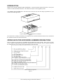
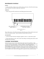
Filter Hood Operating and Installation Manual ___________________________ Spring Air Systems Inc., Oakville, Ontario Phone (905) 338-2999, Fax (905) 338-0179, [email protected] 2013 Update Table of Contents Introduction Spring Air Systems Hood Model Number Designations Hood Installation Instructions Principle of Operation Maintenance Schedule Cleaning the Exterior Trouble Shooting Measuring the Exhaust Airflow Measuring the Exhaust Airflow Measuring the Supply Airflow – MI Models Only Measuring the Supply Airflow – MB Models Only Measuring the Supply Airflow – MB Models Only Measuring the Supply Airflow – MJ Models Only Hood Wiring Requirements Other Fine Products from Spring Air 1 1 2 3 4 4 5 5 6 7 8 9 10 11 12 INTRODUCTION Thank you for selecting a SPRING AIR SYSTEMS INC. commercial kitchen exhaust filter hood. Your system consists of a filter hood and exhaust fan. The exhaust fan may have been supplied by others. Your SPRING AIR SYSTEMS INC. filter hood was selected to best meet the design requirements of your commercial kitchen application. Typical SPRING AIR SYSTEMS Filter FN-B Hood Figure 1 The exhaust fan is normally controlled by an ON/OFF selector switch located in the kitchen area or mounted on the exhaust fan starter coil electrical enclosure. SPRING AIR FILTER HOOD MODEL NUMBERS DESIGNATIONS There are numerous types and styles of SPRING AIR SYSTEM filter hoods available. Refer to the ULC label for the complete model number and exhaust flow requirement for your filter hood. The ULC label is located on the underside of the grease trough on the right hand side of the filter hood. Model Number Designation Figure 2 __________________________________________________________________________________ Filter Hood Operating and Installation Manual 1 HOOD INSTALLTION INSTRUCTION Step 1) Prior to hood installation, please review all hood factory drawings. Step 2) See hood section view drawing for access doors width clearance requirement. If you do not have the proper clearance, call the factory immediately at 1-866-874-4505 Step 3) Carefully uncrate the hood without causing any damages to the hood. Step 4) Once uncrated, do not move hood unless it is supported on its back end to be taken into the building. You may use a pair of “Mover Dollies” or a pair of “Appliance hand Truck” Step 5) Check with the General contractor to confirm that the hanger rods diameter and metal, meet the requirement to support the weight of the hood on the structure. Step 6) Proceed to install the hanger rods to suit the building conditions and as per the local building code. The hanger rods must be plum to the centre of the hanger brackets and perpendicular to the roof of the hoods. Step 7) After the hanger rods have been installed, the hood can now be hoisted to the appropriate height and secured with hanger rod nuts. However, make sure that the tools that are being sued to lift the hood in place do not cause any damages to the hood. Step 8) Once the hood is safely secured and evenly aligned with the hanger rods and hung at the recommend height, the installation is now completed. For further instruction, on the remaining scope of work, refer to the General Contractor. Note, all hoods must be install in accordance with Standard NFPA96 and ULC-S650 __________________________________________________________________________________ Filter Hood Operating and Installation Manual 2 PRINCIPLE OF OPERATION The contaminated exhaust air rises off the cooking equipment and enters the baffle grease filters within the SPRING AIR SYSTEMS filter hood. The exhaust air accelerates through two 90 degree turns within the baffle filters. The liquefied grease then drains down the vertical length of the baffles to the grease trough and into a grease cup. Each grease baffle contains weeping holes to allow the liquid grease to drain into the grease trough Always ensure that the grease filters are installed with the weeping holes down toward the grease trough. The exhaust air travels into the exhaust plenum, fire damper, exhaust duct collar and then into the exhaust ductwork. Greater exhaust and/or lesser supply air may be required for complete vapour and smoke removal in specify installations. __________________________________________________________________________________ Filter Hood Operating and Installation Manual 3 MAINTENANCE SCHEDULE DAILY: 1. At the end of the cooking day wipe off the interior and exterior of the filter hood canopy and the underside of the grease trough with a damp cloth. WEEKLY: 1. Remove the grease filters and wash in a mild detergent and water mixture. WIPE UNDERSIDE OF GREASE TROUGH WIPE INTERIOR OF CANOPY AFTER DAILY COOKING Cleaning the Hood Exterior Figure 5 Wipe off the interior of the filter hood plenum behind the grease filters and the interior and exterior of the grease trough. Remove the grease cup and clean if necessary. SIX MONTHS 1. Check the exhaust fan belts for alignment, tightness, and wear. Adjust and/or replace. 2. Hoods with makeup air only: remove filter from makeup air discharge and wash in a mild detergent and water mixture. CLEANING THE EXTERIOR Normal soil can be removed with a mild detergent and water mixture applied to a cloth. To remove baked on grease, apply a cleanser to a damp cloth or sponge and rub on the metal in the direction of the polishing lines. DO NOT RUB IN A CIRCULAR MOTION. Burnt deposits which do not respond can usually be removed by rubbing the surface with SCOTCH-BRITE Scouring pads or Stainless scouring pads. Do not use ordinary steel wool. Heat tint can be removed by a vigorous scouring in the direction of the polish lines using SCOTCH BRITE or STAINLESS scouring pads in conjunction with a powdered cleanser. __________________________________________________________________________________ Filter Hood Operating and Installation Manual 4 TROUBLE SHOOTING Low air (i) Improper exhaust fan rotation. (ii) Broken or slipping belt. (iii) Exhaust ductwork inspection door open. (iv) Obstruction in the ductwork. (i) Broken belt. (ii) Exhaust fan overload tripped. (iii) Exhaust fan disconnect open. (iv) Exhaust fan motor fuse blown. No air MEASURING THE EXHAUST AIRFLOW The exhaust air is measured along the inlet slot of the ventilator. To ensure accurate results take a reading every one foot along the length of the ventilator. VANAXIAL VELOMETER Hold the instrument perpendicular to the VORTEX BAFFLE and parallel to the throat (inlet slot) of the ventilator. Velometer should not exceed three inches in diameter. 2" BAFFLE FILTER VELOMETER BACK OF HOOD INSIDE HOOD CANOPY GREASE CUP Measuring Exhaust Air Figure 6 PITOT TUBE OR ANOMETER Hold the instrument perpendicular to the VORTEX BAFFLE and parallel to the throat (inlet slot) of the ventilator. Take three reading across the throat and average the results. BAFFLE FILTER BACK OF HOOD 2 INSIDE HOOD CANOPY PITOT TUBE 1 Measuring Exhaust air __________________________________________________________________________________ Filter Hood Operating and Installation Manual 5 Figure 7 Calculate the average velocity across the inlet slot and refer to the chart below for the corresponding exhaust volumes. Add the individual exhaust volumes to determine the total exhaust. Exhaust Air Flow Per Filter Baffle Filter Size in x in mm x mm 20 x 16 508 x 406 20 x 20 508 x 508 20 x 25 508 x 635 Average Filter Velocity 100 fpm/0.5m/s 200 fpm/1.0m/s CFM l/s CFM l/s 200 94 400 189 260 123 520 245 320 151 640 302 Chart No. 1 300 fpm/1.5 m/s CFM l/s 600 283 780 368 960 453 Use the chart below when measuring the velocity in the filter slot with a hot wire anemometer. Place the hot wire anemometer directly in the filter slot level with the adjacent baffle. Take four readings up and down each slot in every other slot of each filter. Average these readings to use the chart below. The chart is only applicable when using a hot wire anemometer. Velocity (fpm)* 100 200 300 400 500 600 700 800 900 1000 1100 1200 1300 1400 1500 1600 1700 1800 Filter Size/Slot Velocity vs Exhaust Volume Filter Size vs CFM per filter 20 x 20 (CFM) 60 120 180 240 300 350 410 470 530 590 650 710 770 830 890 940 1000 1060 20 x 25 (CFM) 70 140 210 270 350 410 480 550 620 690 760 830 900 970 1040 1100 1170 1240 12 x16(5)+ (CFM) 30 60 90 120 150 170 200 230 260 290 320 350 370 410 440 460 490 520 12 x16(4)! (CFM) 20 40 70 90 110 140 160 180 200 230 250 280 300 320 350 370 390 420 * Slot velocity measured with hot wire anemometer + Filter in rack with 5 slots facing out. ! Filter in rack with 4 slots facing out. __________________________________________________________________________________ Filter Hood Operating and Installation Manual 6 MEASURING THE SUPPLY AIRFLOW - MI MODELS ONLY The supply air discharge from a FN-B-MI or FN-DB-MI is measured along the internal discharge perforated plate inside the filter hood canopy. To ensure accurate results take a reading every one foot along the length of the filter hood. VANAXIAL VELOMETER Hold the instrument parallel to and about one (1) inch from the perforated discharge slot. "MI" PLENUM INSIDE HOOD CANOPY FRONT OF HOOD VELOMETER Measuring Supply Air Figure 8 PITOT TUBE OR ANEMOMETER Hold the instrument parallel to and about one (1) inch from the perforated discharge slot. Take two readings across the slot and average the results. INSIDE HOOD CANOPY 2 1 "MI" PLENUM PITOT TUBE FRONT OF HOOD Measuring Supply Air Figure 9 Calculate the average velocity along the length of the perforated discharge and refer to chart No. 2 for corresponding CFM/ft (l/s/m). If the supply air is too high adjust the opposed blade dampers on top of the filter hood at the supply air inlets just above the supply fire dampers. Multiple dampers can be balanced to provide the velocity profile required across the supply discharge. Supply Velocity vs Supply Flow Rate Supply Discharge Velocity fpm m/s 400 2.1 600 3.1 800 4.1 1000 5.1 Supply Flow Rate CFM/ft 120 180 240 300 l/s/m 186 372 372 466 Chart No.2 __________________________________________________________________________________ Filter Hood Operating and Installation Manual 7 MEASURING THE SUPPLY AIRFLOW - MB Measuring the total supply fan airflow through the Blade: _____1. Remove Blade front discharge perforated panel with appropriate tools. _____2. Turn Blade’s threaded rod counter-clockwise until the Blade comes to a fully open position, which is required to determine the total supply volume at each hood. _____3. Turn supply fan on. _____4. Re-install Blade front discharge perforated plate with appropriate tools. _____5. Take velocity reading across the perforated plate as shown in the diagram below. Take two vertical readings, one at 2” from the bottom of perforation and one at 4”. Repeat these horizontal readings every 12” along the hood. _____6. Total all readings and divide by the number of reading to determine the average velocity. _____7. Multiply the average velocity x 72 x length of perforated panel (in inches) to determine the total CFM per perforated panel. (It is critical to take the velocity readings 1” off the surface of the perforated panel to use this formula). _____8. If the total supply volume was not correct and Spring Air Systems provided the supply fan/unit then adjust the supply volume at the fan/unit or at field supplied balancing dampers. If the supply fan/unit was not provided by Spring Air Systems advise the general contractor to adjust the supply air volume and do not proceed unit the volume has been correct. The total supply volume required can be found on the Spring Air Systems shop drawings. __________________________________________________________________________________ Filter Hood Operating and Installation Manual 8 Measuring supply airflow through the Custom Comfort Dial: _____1. Remove Blade front discharge perforated panel with appropriate tools. _____2. Turn Blade’s threaded rod clockwise until the blade is 1.5 inches off the vertical front surface of the hood. See diagram below. _____3. Set the velometer parallel to the bottom discharge with the face open perpendicular to the perforated screen where the air discharges and take a reading every 12” apart for the full length of the hood. See diagram below. _____4. Total all velocity readings and divide by the number of reading to determine the average velocity. _____5. Refer to Custom Comfort Dial Velocity Chart below. Based on the hood length and the temperature rating indicated on the UL/ULC plate determine the Custom Comfort Dial Velocity. _____6. If the measured average velocity is too high, turn the Blade threaded rod counter-clockwise 5 times. Re-measure average velocity. Repeat until the measured velocity at Custom Comfort Dial is correct. _____7. If the measured average velocity is too low, turn the Blade threaded rod clockwise 5 times. Re-measure average velocity. Repeat until the measured velocity of Custom Comfort Dial is correct. FN or FB Hood Custom Comfort Dial Velocity Chart APPLIANCES Heavy - Charbroiler Heavy - Charbroiler Heavy - Charbroiler Heavy - Charbroiler TEMP. 6000 F 6000 F 6000 F 6000 F Hood Length (ft) 9 - 14 6-9 4-6 Up to 4 CCD VELOCITY (fpm) FRONT Set point 500 500 550 550 SIDE FLOW Set point 450 450 450 450 Medium – Griddle, fryer 4000 F 9 - 14 450 400 Medium – Griddle, fryer 4000 F 6-9 450 400 Medium – Griddle, fryer 4000 F 4-6 450 450 Medium – Griddle, fryer 4000 F Up to 4 450 450 __________________________________________________________________________________ Filter Hood Operating and Installation Manual 9 MEASURING THE SUPPLY AIRFLOW - MJ The supply air is measured along the bottom inside discharge opening of the make up air plenum. To ensure accurate results take a reading every one foot along the length of the ventilator. Measure supply air flow through comfort dial: _____1. Ensure the MJ blowers are powered when the exhaust fan is activated. _____2. Locate the rheostat on the back of the MJ Blower which is on top of the MJ plenum. _____3. Turn the rheostat 120 degree clock-wise to activate the MJ blower. _____4. Set the velometer parallel to the bottom discharge with the face open perpendicular to the perforated screen where the air discharges and take a reading every 12” apart for the full length of the hood. The first reading should be one inch from the end and continue every twelve inches to the opposite end of the ventilator. _____5. Total all velocity readings and divide by the number of readings to determine the average velocity. _____6. Refer to Custom Comfort Dial Velocity Chart below. Based on the hood length and the hood temperature rating indicated on the UL/ULC plate determine the Custom Comfort Dial velocity on the chart. _____7. If the measured average velocity is not correct adjust the rheostat as follows: Rotate clockwise for lower or counterclockwise for higher velocity. Retake the velocity reading to confirm the recommended set point. FN or FB Hood Comfort Dial Velocity Chart APPLIANCES TEMP. Hood Length (ft) Heavy - Charbroiler Heavy - Charbroiler Heavy - Charbroiler Heavy - Charbroiler 6000 F 6000 F 6000 F 6000 F 9 - 14 6-9 4-6 Up to 4 Medium – Griddle, fryer Medium – Griddle, fryer Medium – Griddle, fryer Medium – Griddle, fryer 4000 F 4000 F 4000 F 4000 F 9 - 14 6-9 4-6 Up to 4 CD VELOCITY (fpm) FRONT SIDE FLOW Set point Set point 500 450 500 450 550 450 550 450 450 450 450 450 400 400 450 450 __________________________________________________________________________________ Filter Hood Operating and Installation Manual 10 Hood Wiring Requirements An installation wiring diagram shall be provided with each control unit illustrating the field connections to be made. The drawings may be attached to the unit or, if separate, shall be referenced in the marking label attached to the unit with the drawings or issue number, and date. The drawing shall show a particular view of the installation terminals or leads to which field connection are made as they would appear when viewed during an installation. The terminal numbers on the control unit shall agree with the numbers on the drawing. A drawing not attached to the control unit shall be marked with the name or trademark of the manufacturer, drawing or issue number, and date. Note, all electrical site work must be completed as per National and local Electrical Codes. Options __________________________________________________________________________________ Filter Hood Operating and Installation Manual 11 Other Fine Products From RevLow Hoods DynaFlow Hoods TruFlow Energy Management Systems UL/ULC Listed Pollution Control Systems Dry Extractor Hoods Catridge Hoods Filter Hoods Water Wash Ventilators Surface Fire Suppression Commercial Kitchen Exhaust Fans Commercial Kitchen Supply Units Utility Distribution Systems Phone: 866-874-4505, FAX: 905-338-0179 [email protected] www.springairsystems.com __________________________________________________________________________________ Filter Hood Operating and Installation Manual 12