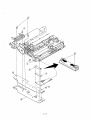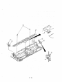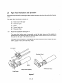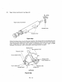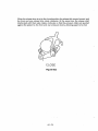
1
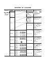
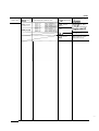
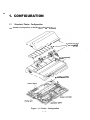
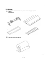
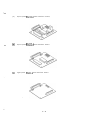
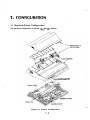
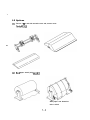
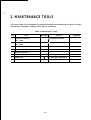
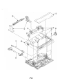
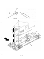
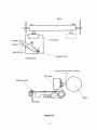
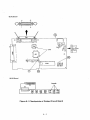
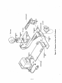
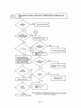
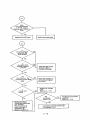
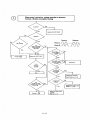
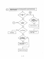
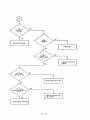
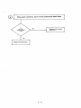
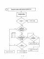
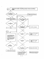
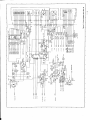
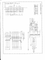
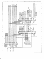
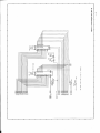
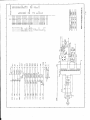
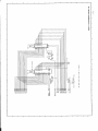
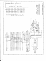
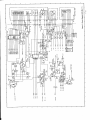
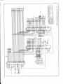
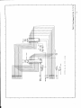
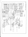
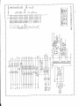
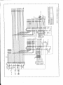
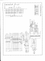
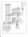
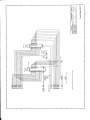
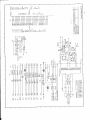
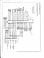
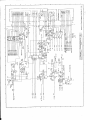
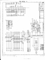
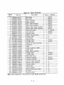
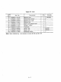
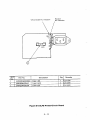
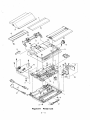
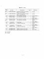
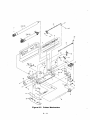
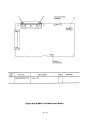
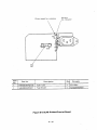
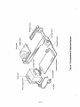
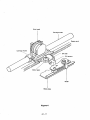
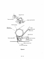
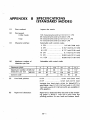
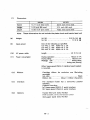
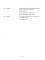
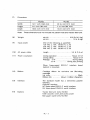
/L
(ii,’’,
i/
MICROLINE 182/183 PRINTER
MAINTENANCE MANUAL
;
.,.
PREFACE
This maintenance manual describes field maintenance of the Microline 182/l 83 for
maintenance engineers.
For performance specifications and operating procedures, refer to the “User’s Manual”.
CONTENTS
Page
CONFIGURATION . . . . . . . . . . . . . . . . . . . . . . . . . . . . . . . . . . . . . . . . . . . . . . . . . . . . . . . . .
1.1
Standard Printer Configuration . . . . . . . . . . . . . . . . . . . . . . . . . . . . . . . . . . . . . . .
1.2
Options . . . . . . . . . . . . . . . . . . . . . . . . . . . . . . . . . . . . . . . . . . . . . . . . . . . . . . . . . . . . .
l-l
l-l
1-2
MAINTENANCE TOOLS . . . . . . . . . . . . . . . . . . . . . . . . . . . . . . . . . . . . . . . . . . . . . . . . . . . .
2-1
PARTS REPLACEMENT . . . . . . . . . . . . . . . . . . . . . . . . . . . . . . . . . . . . . . . . . . . . . . . . . . . . .
3.1
Precautions for Parts Replacement . . . . . . . . . . . . . . . . . . . . . . . . . . . . . . . . . . .
3.2
Disassembly and Reassembly Procedures . . . . . . . . . . . . . . . . . . . . . . . . . . . .
3-l
3-l
3-2
CLEANING
4-l
.................................................. ..............
ADJUSTMENT
.
.............................................................
5-l
TROUBLESHOOTING AND REPAIR . . . . . . . . . . . . . . . . . . . . . . . . . . . . . . . . . . . . . . . .
Items to be Checked Before Repair . . . . . . . . . . . . . . . . . . . . . . . . . . . . . . . . . .
6.1
Method of Troubleshooting . . . . . . . . . . . . . . . . . . . . . . . . . . . . . . . . . . . . . . . . . . .
6.2
Connection Circuit and Resistance Check for
6.3
Print Head and LF/SP Motor . . . . . . . . . . . . . . . . . . . . . . . . . . . . . . . . . . . . .
6-l
6-1
,6-l
Cl RCUIT DIAGRAM . . . . . . . . . . . . . . . . . . . . . . . . . . . . . . . . . . . . . . . . . . . . . . . . . . . . . . . . .
7-l
MAINTENANCE PARTS LIST . . . . . . . . . . . . . . . . . . . . . . . . . . . . . . . . . . . . . . . . . . . . . . . . .
8-1
THEORY OF OPERATION
SPECIFICATIONS (STANDARD MODEL)
SPECIFICATIONS (IBM COMPATIBLE MODED
DIP SWITCH SETTING TABLE, (STANDARD MODEL)
DIP SWITCH SElTlNG TABLE (IBM COMPATIBLE MODE0
6-5
RECORDS OF CHANGES
Part No.
EC0 No.
Printer/PCB Serial No.
OKI-J Par1
No.
M-52033;
ISSUE 1
Page affected
Description of
changes
i-24, 3-25,3-28, F;“;c;t;entj
1-29,
i-9, 8-10,
(Addition)
M-5, AA-IO,
:ront-cover,
‘reface, l-1,
i-2, 3-34
i-2 to 8-8
IB-1, AB-2
IC-I, AC-2
Descriptions of
ML183 are added.
(Replacement)
Circuit, diagram
(Rev. 7) of SLMC-2
circuit board is
added.
(Addition)
‘-27 to 7-33
NML-007
NML-035
NML-053
NML-063
ML182
220 v
240 V
501 A00001 61
501A0000041
ML183
220 v
240 V
501 A0000001
501 A0000001
ML182
220 v
240 V
504AOOO9311
504A0004441
ML183
220 v
240 V
I
7-43 to 7-49
-
ML182
220 v
240 V
506AOO12961
506A0007001
ML183
220 v
240 V
506A0000009
506A0000003
ML1 82
220 v
240 V
508A0016961
508A0008501
ML183
220 v
240 V
Circuit diagram
(Rev. 8) of SLMC-2
circuit board is
r-35 to 7-41
added.
(Addition)
7-51 to 7-57
7-59 to 7-69
506A0000009
506A0000003
Circuit diagram
(Rev. 9) of SLMC-2
circuit board is
added.
(Addition)
Circuit diagram
(Rev. 10) of SLMC-2
circuit board is
added.
(Addition)
Circuit diagram
(Rev. 11) of SLMC-2
circuit board is
added.
(Addition)
(con.)
Part No.
EC0 No.
Printer/PCB Serial No.
>age affected
Description of
changes
\E-1
Change of DIP
switch functions
LReplacement)
LB-3
(Deletion)
iack cover
Renewal of issue
(Replacement)
rD1, AD2
1. CONFIGURATION
‘\._
_,.
1. CONFIGURATION
1.1
Standard Printer Configuration
The standard configuration of the ML 182/l 83 is as fOllOws:
tractor feed unit
_ A (ML183 only)
COW assembly
er SUDPIY
Control board
,:
Figure l-1 Printer Configuration
l - l
assembly
1.2 Options
(l),
(2)
,Tractor feed unit with acoustic cover, access cover and paper separator
(only ML1 82)
Roll paper stand (only ML182)
‘._
.-,
(3)
Super-speed RS232-C serial interface board,
(4)
Super-speed RS422-A serial interface board
(5)
High-speed RS422-A serial interface board
:
l-3
I. CONFIGURATIO’N
1.1 Standard Printer Configuration
The standard configuration of the ML 182/l 83 is as follows:
y/.Power supply assembly
v//Ribbbn cartridge
Figure l-1 Printer Configuration
1 -,4
1.2 Options
(1)
Tractor f ee d unit with acoustic cover and, access cover.
,(only Mll82)
__
(2)
Roll paper stand (only MLJ 82)
with paper row detection
micro switch
1-5
2. MAINTENANCE
‘L
2. MAINTENANCE TOOLS
The tools in table 2-l are necessary for replacing printed-circuit boards and unit parts. For other
maintenance procedures, different tools may be necessary.
Table 2-l Maintenance Tools
No.
Tool
Quantity
Purpose
1
Phillips screwdriver
No. l-100
1
2- to 2.6-mm screws
2
Phillips screwdriver
No. 2-200
1
3- to 5-mm screws
3
Screwdriver No. 3-100
1
4
Cutters No. 5H
1
5
Round pliers No. 1
1
6
Thickness gauge set
1
for head gap adjustment
7
Metal rod
1
for head gap. adjustment
a
Volt-ohm-milliammeter
1
2-l
Remarks
3, PARTS REPLACEMENT
.._
3. PARTS REPLACEMENT
3.1
(1)
(2)
.~~
Precautions for Parts Replacement
Be sure to turn OFF the AC POWER switch and remove the AC,input plug from the AC
receptacle before disassembly or reassem’bly.
Don not disassemble the printer as long as it is in good operating condition.
(3)
Be careful not to remove parts unless, necessary. Disassembly should be the minimum
necessary.
(4)
Use only the specified maintenance tools.
(5)
Disassemble the printer in the specified order of disassembly procedures; otherwise,
parts may be damaged.
(6)
In the course of disassembly, it may be agood ideato keep the removed small parts such
as screws and washers by attaching them temporarily to their original places so as not to
lose them.
(7)
KS such as the microprocessor, ROM, and RAM can easily be damaged by static
electricity. Do not wear gloves that are apt to produce static electricity when handling
printed-circuit boards.
(8)
Do not place the printed-circuit boards directly on the printer or the floor.
3 - l
3.2
Disassembly and Reassembly .Procedures
3.2.1
Upper cover
(1)
Turn OFF the AC POWER switch, and remove AC cable @ from the outlet, and then
remove interface cable @ , remove paper.
(2)
Remove acoustic cover and paper separator (if installed).
(3)
Remove tractor feed unit @ by depressing lock lever @ and tilting backward (if it is
installed).
(4)
Remove roll paper with paper shaft @ by lifting upward. Remove side frame @ by
tilting forward (if it is installed).
(5)
Remove access cover @ by lifting rear, edge.
(6)
Pull platen knob @ out
(7)
Remove two screws’@.
(8)
Remove upper cover @ by lifting up front and pushing it backward.
(9)
For reassembly, reverse the disassembly procedure.
3-2
3 i3
3.2.2
Control board
(1)
Remove the upper cover (see 3.2.1).
(2)
Remove serial interface board by removing two screws locating on both sides of
interface connector. Remove interface board upward (if installed).
(3)
Remove transformer connector @ from the, control board @ .
(4)
Remove three screws @ and two screws @.
(5)
Remove control board @ by !ifting upward (see Notes below). Observe’paper nearend lever when removing the PCB.
(6)
Before reassembly, secure rubber insulator @ is, installed.
(7)
For reassembly, reverse the disassembly procedure..
Notes:
7.
Do not”fouch the terminal (contact) @for connector @directly with hand and make
sure that if ,i.s clean.
2.
When affachin , make sure that pa er near-end lever 0 is c/ear in the groove of
phofosensor 6
8 on control board 6
1 .
3-4
3.2.3 Transformer assembly
(1)
Remove the upper cover (see 3.2.1).
(2)
Remove connector @ from the control board.
(3)
Remove ground strap screw @
(4)
Remove two screws 0.
(5)
Remove transformer assembly@ with power PCB@ and AC cord receptacle @ by
lifting upward.
(6)
For reassembly, reverse the disassembly procedure.
3-6
View A
3-7
3.2.4 Power supply board
(1)
Remove the upper cover (see 3.2.1).
(2)
Remove the transformer asssembly (see 3.2.3).
(3)
Remove power supply board @ from transformer @ by pulling off connection pins
0.
(4)
For reassembly, reverse the disassembly procedure.
Note: When attaching, set the powersupplyboard @ along guide @ before assembling.
3-8
3-9
3.2.5 Operation board
(1)
Remove the upper cover (see 3.2.1).
(2)
Disengage two tabs 0.
(3)
Remove connector @ connecting the connection board and operation board.
(4)
Remove operation board 0.
(5)
For reassembly, reverse the disassembly procedure.
Note: Be careful not to damage the cab/e connecting the switch and the connector.
.-
3-10
3-11
3.2.6
0)
Print head
Turn OFF the AC POWER switch, and remove AC cable @ fiom the outlet.
Caution:
(2)
Print head may be hot after printing.
Remove access cover @ by lifting up rear edge of cover.
(3)
Remove ribbon cartridge @ by gently squeezing both sides ‘@ 2nd lifting up.
(4)
Raise head clamp @ by swinging right tab up (see figure).
(5)
Remove print head @ by lifting straight up.
(6)
For reassembly, reverse the disassembly procedure.
‘~.
Note: heft the’print head in connect6r 0 &i/epres+ing it agztinst the carriage frame@.
3-12
3-13
3.2.7
Ribbon feed gear assembly
(1)
Remove the upper cover (see 3.2.1).
(2)
Remove ribbon cartridge @ by lifting both sides@
(3)
Disengage the two front tabs @ and two rear tabs@ (total of four tabs). Then lift
upward by inserting small flat screwdriver to slots.
(4)
Remove ribbon feed gear assembly @.
(5)
Remove carriage cable @ , cable holder 8, and contact pressure rubber @ from
ribbon feed gear assembly @.
6)
For reassembly, reverse the disassembly procedure.
Notes:
1.
D not touch the carriage cable @ and space motor assembly @ terminal (contact)
6B directly with hand and make sure that it is clean.
2.
Make sure the carriage cab/e @ is not folded.
3. After installing ribbon feed gear assembly @, check and adjust the gap between the
platen and print head (see section 5).
3-14
3 - 1.5
3.2.8
Space motor assembly
(1)
Remove the upper cover (see 3.2.1).
(2)
Remove the print head (see 3.2.6).
(3)
Remove the ribbon feed gear assembly (see 3.2.7).
(4)
Remove connector 0, and observe concave surface.
(5)
Remove three screws 0.
6)
Remove space motor assembly 0.
(7)
For reassembly, reverse the disassembly procedure.
Notes:
1. Do not touch the space motor assembly @ terminal (contact) @ direcfly with hand
and make sure that if is clean.
2.
When installing space motor assembly 0, put the @ side of the assembly close to
carriage frame @, and align the @ side of the assembly with the corresponding side
of the carriage frame.
3.
When installing slider 0, put the @ and @parts of the slider close to space motor
assembly 0.
4.
Afterinstalling space motorassembly 0, checkandadjusf fhegap between fheplafen
and print head (see section 5).
3-16
@*----$
i
i
3-17
3r2.9 Space rack
(1)
Remove the upper, cover (see 3.2.1).
(2)
Remove the print head (see 3.2.6).
(3)
Remove the ribbon feed gear assembly (see 3.2.7).
(4)
Remove the space motor assembly (see 3.2.8).
(5) Remove spring 0.
(6) Disengage tab 0.
(7)
Remove by inserting a minus screwdriver between space rack @and base frame @
and gently pushing the space rack @ up.
(8)
For reassembly, reverse the disassembly procedure.
Note:
After installing space motor assembly, check and adjust the gap between the
platen and print head (see section 5).
3-78
c..
1
‘.
?
3-19
32.10 Carriage cable
(1)
Remove the upper cover (see 3.2.1).
(2)
Remove the print head (see 3.2.6).
(3)
Remove the ribbon feed gear assembly (see 3.2.7).
(4)
Remove the space motor assembly (see 3.2.8).
(5)
Remove the space rack (see 3.2.9).
(6)
Unlock the two tabs @ and remove cord clamp 0.
(7)
Remove contact rubber 0.
(8)
Remove carriage cable (ZJ.
(9)
For reassembly, reverse the disassembly procedure. ~,
Notes:
1. Do not ,tooch the carriage cable
direct/y with hand and make
2.
and connection board @ terminal (contact) @
Make sure the carriage cab/e @ is not folded.
3. AfterinstaNingspacemotorassembly, checkandadjusf thegap between theplatenand
print head (see section 5).
3 - 20
3 - 21
3.2.11 Printer mechanism
(1)
Remove the upper cover (see 3.2.1).
(2)
Remove connector @ connecting the control board @ and transformer assembly@.
(3)
Remove ground ‘strap screw 0.
(4)
Remove the operation board (see 3.2.5).
(5)
Remove four screws @) and washers @.
6)
Rem&e printer mechanism 0.
(7)
Remove three screws@, two screws 0, and control board @.
(8)
Foi reassembly, reverse the disassembly procedure.
3 - 22
3 - 23
3.2.12 LF motor assembly
(1)
(2)
Remove the upper cover (see 3.2.1).
Remove the printer mechanism. (See 3.2.11 step 7. The control board need not be
removed.)
(3)
Remove two screws 0.
(4)
Remove LF motor assembly 0.
(5)
For reassembly, reverse the disassembly procedure.
Notes:
I. DO not touch the LFmotorassembly @ terminal(confacf) @directly with handor fold
it and make sure that if is clean.
2.
Move the bias ge r @ to the platen gear @ as indicated by the arrow then engage
D . (The bias gear @ is differentiated by half of a tooth with respect
them at portioh 6
to the tooth of platen gear @ .)
3.
When assembling the Lf motor assembly 0, loosen the screw @ fastening the
connection board and make a space between the base and connection board. Then
inStall the LF motor whi/e pressing it against. @ and @.Then tighten the screw @
fastening the connection board.
4.
After assembling, make sure that the platen gear @ is correctly engaged and the
platen turns smoothly.
3-24