1
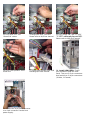
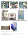
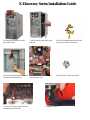
X-Discovery Series Installation Guide
1:Unscrew the thumb screws
from Side Panel.
2.Pull the side panel back then
pull out.
3:Find the motherboard stand-offs
from the enclosed screw box.
4:Put the motherboard stand-offs
on the motherboard tray.
5.Sit the motherboard on the
motherboard tray.
6.Find screws in the screw box.
7.Screw in all the screws into the
motherboard stand-offs
8.Same as Step 7.
9.Take out front panel:(You need to take out both side panels first to unscrew front panel screws)
Step (1): Unscrew both side
panels
Step (2): Take out both side
panels
Step (3): There are 4 screws that
hold the front panel to the case. (2
on each side) Unscrew 2 screws from
the back of front panel on one side.
Step (4): Unscrew the other
2 screws from the other side.
Step (5): Pull out the front
panel from the bottom.
10.Front Case Fans (Optional):
You can put up to 2*80mm fans
in the front.
11.Force out the 5.25” metal
plate from inside with a screw
driver, then insert 5.25” drive.
12.Screw all 5.25” drives
in place.
13.3.5” External Drives:
Force/push out 3.5” metal plate
and install 3.5” external drives.
14.3.5” Internal Drives:
Install 3.5” hidden drivers such
as hard drive and zip drive.
15.Screw all 3.5” hidden drivers
in place.
16.Put the front panel back
and screw back the 4 screws
to secure the front panel.
17.Find the 20pin/or 24pin main
connector from Power Supply.
18.Plug into your motherboard.
19.Find the 4-pin P4 connector
Different M/B has different layout. from power supply.(for P4 only)
If you have AMD or P3 board,
You do not need to connect it.
20.Plug into your motherboard.
(For Intel P4 motherboard only)
Please refer to M/B user manual.
21.Find 2*USB Cables.(USB1
& USB2)
22.Plug USB cables to your M/B.
Please refer to M/B User Manual.
23.Find “HDD LED” and
“Reset SW” cables.
24.Plug them onto your M/B.
Please refer to M/B user manual.
25.Find “Power SW” and “+P LED”
“-P LED” cables and plug onto M/B.
Please refer to M/B user manual.
26.Find “Case Speaker” from
screw box.
27.Install case speaker onto M/B
following M/B user manual.
29.Connect the 4-pin Male connector
to a 4-pin connector Female from
power supply.
28. Install LED Lights: Find 2*
LED connectors from the front
Panel. They are 2*2-pin connectors
that lead out to 2*4-pin connectors
(1*Male, 1*Female)
30.Install LCD Temperature Readout:
Step (1): Connect 4-pin Male
Step (2): Remove the protective
connector from LCD to a 4-pin
plastic tube from the sensor.
Female connector from Power Supply. tube from the sensor.
Step (3): This is the temperature
sensor. It’s very fragile. Be gentle.
from power supply.
31.You can either tape the sensor on hard drive or on CPU Heat
32.Once powered on, the LCD shows
sink or leave it inside the case to get the overall system temperature. temperature readout with back lighting.
33.Find “Case Feet” in the screw box.
Lay case down and put “Case Feet” on.
34.View from side window panel
After installation.
Note:
1.You can link together all the 4-pin connectors(male to female) from all the case fans, LCD, LED, HDD and
just use one of the 4-pin Molex connectors from power supply. That will leave you more 4-pin Molex connectors
from your power supply for other devices.