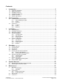
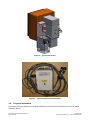
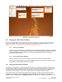
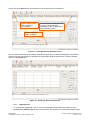
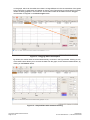
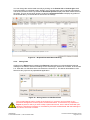
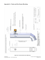
1
User Manual
CT2100 On-Stack Emissions Sensor
Document Number: D-7010-0005
Revision 1, 14th November 2008
Published by Cascade Technologies Ltd.
All possible care has been taken in the preparation of this publication, but Cascade Technologies, its agents
and distributors accept no liability for any inaccuracies that may be found. This manual reflects the state of
the product at the issue date below, but further enhancements while in service may mean that the manual
does not reflect your particular system.
Cascade Technologies reserves the right to make changes without notice both to this publication and the
products which it describes.
Document Number: D-7010-0005
Revision 1, 14th November 2008
© Cascade Technologies Ltd. 2008
No part of this publication may be reproduced, stored in a retrieval system or transmitted in any form or by
any means electronic, mechanical, photocopying, recording or otherwise without the express prior written
permission of the copyright holder.
Cascade Technologies Limited.
Unit A, Logie Court
Stirling University Innovation Park
Stirling
FK9 4NF
United Kingdom
All trademarks used within this document are the property of their respective owners.
Caution – use of controls or adjustments or performance of procedures other than those
specified herein may result in hazardous radiation exposure.
CT2100 On-Stack Emissions Sensor
Page 2 of 27
User Manual
D-7010-0005 Revision 1, 14th November 2008
Contents
1.
Introduction ...............................................................................................................5
1.1.
1.2.
1.3.
1.4.
1.5.
1.6.
2.
Site Preparation.........................................................................................................7
2.1.
2.2.
3.
3.5.
4.6.
4.7.
4.8.
System Start-Up.......................................................................................................................... 15
CT2100 Probe............................................................................................................................. 15
Gas Sensor ................................................................................................................................. 15
Control P.C.................................................................................................................................. 15
Running the Gas Sensor Software ............................................................................................. 16
4.5.1. Running with Modbus .................................................................................................... 16
4.5.2. Running with without Modbus........................................................................................ 16
Using the Gas Sensor Software.................................................................................................. 16
4.6.1. Graphing Data................................................................................................................ 17
4.6.2. Saving Data ................................................................................................................... 19
Modbus Test Client ..................................................................................................................... 20
4.7.1. Graphing and Saving Data ............................................................................................ 20
External Data Logger .................................................................................................................. 21
System Removal......................................................................................................22
5.1.
5.2.
6.
Tools Required.............................................................................................................................. 9
Handling Precautions .................................................................................................................... 9
Materials Supplied......................................................................................................................... 9
Physical Installation..................................................................................................................... 10
3.4.1. CT2100 Probe................................................................................................................ 11
3.4.2. Gas Sensor .................................................................................................................... 11
3.4.3. Ethernet Switch.............................................................................................................. 13
3.4.4. Control P.C. ................................................................................................................... 13
System Configuration.................................................................................................................. 13
3.5.1. Gas Sensor .................................................................................................................... 13
3.5.2. Ethernet Switch.............................................................................................................. 13
3.5.3. Control P.C. ................................................................................................................... 14
3.5.4. Modbus .......................................................................................................................... 14
Operation .................................................................................................................15
4.1.
4.2.
4.3.
4.4.
4.5.
5.
CT2100 Probe and Gas Sensor.................................................................................................... 7
2.1.1. Stack Stabbing Location .................................................................................................. 7
2.1.2. Power............................................................................................................................... 7
2.1.3. Ethernet ........................................................................................................................... 7
Control P.C.................................................................................................................................... 8
2.2.1. Location ........................................................................................................................... 8
2.2.2. Power............................................................................................................................... 8
2.2.3. Ethernet ........................................................................................................................... 8
Installation .................................................................................................................9
3.1.
3.2.
3.3.
3.4.
4.
Customer Information.................................................................................................................... 5
Safety Precautions ........................................................................................................................ 5
Qualified Personnel....................................................................................................................... 5
Compliance Approvals .................................................................................................................. 5
System Overview .......................................................................................................................... 6
System Specification..................................................................................................................... 6
Removing the Gas Sensor from the Probe ................................................................................. 22
Removing the Probe from Stack ................................................................................................. 22
Maintenance.............................................................................................................23
6.1.
6.2.
6.3.
6.4.
Schedule ..................................................................................................................................... 23
6.1.1. As Required ................................................................................................................... 23
6.1.2. Quarterly ........................................................................................................................ 23
Probe Filters................................................................................................................................ 23
6.2.1. Probe Course Filter........................................................................................................ 23
6.2.2. Probe Fine Filter ............................................................................................................ 25
Gas Sensor ................................................................................................................................. 26
Control P.C.................................................................................................................................. 26
User Manual
D-7010-0005 Revision 1, 14th November 2008
CT2100 On-Stack Emissions Sensor
Page 3 of 27
7.
Troubleshooting ......................................................................................................26
Appendix A – Probe and Gas Sensor Mounting ...........................................................27
Figure 1 – CT2100 On-Stack Emission Sensor Overview ................................................................................ 6
Figure 2 – Typical CT2100 Probe...................................................................................................................... 9
Figure 3 – Typical Gas Sensor ........................................................................................................................ 10
Figure 4 – Typical Temperature Control Box .................................................................................................. 10
Figure 5 – CT2100 System Assembly ............................................................................................................. 11
Figure 6 – Gas Sensor Mounting Position on Probe Slide Rail....................................................................... 12
Figure 7 – Gas Sensor Connections ............................................................................................................... 12
Figure 8 – Connections on Orange Box .......................................................................................................... 13
Figure 9 – Network Connectivity...................................................................................................................... 14
Figure 10 – Control P.C. Desktop.................................................................................................................... 16
Figure 11 – Initial Gas Sensor Software Screen ............................................................................................. 17
Figure 12 – Analysing Gas Concentrations..................................................................................................... 17
Figure 13 – Dragging Data to be Graphed ...................................................................................................... 18
Figure 14 – Graphed Data with Automatic Scaling ......................................................................................... 18
Figure 15 – Graphed Data with Manual Scaling.............................................................................................. 19
Figure 16 – Saving Data to a USB Flash Drive ............................................................................................... 19
Figure 17 – Modbus Test Client ...................................................................................................................... 20
Figure 18 – Modbus Server Opened ............................................................................................................... 20
Figure 19 – Modbus Data Graphed ................................................................................................................. 21
Figure 20 – Removing the End Cap from Course Filter Tube ......................................................................... 24
Figure 21 – Removing the Spring from Course Filter Tube............................................................................. 24
Figure 22 – Removing the Filter Rod from Course Filter Tube ....................................................................... 24
Figure 23 – Coarse Filter Assembly ................................................................................................................ 25
Figure 24 – Removing the End Cap from Fine Filter Fitting ............................................................................ 25
Figure 25 – Fine Filter...................................................................................................................................... 25
Figure 26 – Optics Shield Outer Retaining Screws ......................................................................................... 26
Figure 27 – Optics Shield Inner Retaining Screws.......................................................................................... 26
Figure 28 – Probe and Gas Sensor Mounting................................................................................................. 27
Table 1 – CT2100 System Specifications.......................................................................................................... 6
Table 2 – Gas Sensor Power Connector Wiring ............................................................................................... 7
Table 3 – Modbus Register Mapping............................................................................................................... 14
CT2100 On-Stack Emissions Sensor
Page 4 of 27
User Manual
D-7010-0005 Revision 1, 14th November 2008
1.
Introduction
1.1.
Customer Information
This manual contains all the information required to install, operate and maintain the CT2100. Please read
the manual carefully before you start work on the Emission Sensor, since it contains important information
that must be followed to guarantee the correct operation of the CT2100 and the safety of personnel. The
manual is divided into sections, which should allow users to rapidly find the information they need for any
stage in the CT2100’s life cycle.
Cascade Technologies is committed to continuously improving its products and documentation. Every effort
will be made to include any Emission Sensor modifications by the manufacturer in the documentation.
However it should be noted that this document reflects the supplied Emission Sensor as of the revision
number and date on the front cover.
Should you require further information, or should particular problems arise that are not covered within this
manual, help can be requested from Cascade Technologies or their distribution partners.
1.2.
Safety Precautions
Certain parts of the CT2100 Emissions Sensor carry dangerous voltages. All housings must be
closed, the Gas Sensor mounted and connected to the probe before switching on. Death,
personal injury and/or damage to persons and/or property may result if this is not observed.
Caution – use of controls or adjustments or performance of procedures other than those
specified herein may result in hazardous radiation exposure.
The CT2100 described in this manual has been quality control tested and left the manufacturer in perfect
condition. To achieve the correct and safe operation of the product, it must be transported, installed,
operated and maintained as described by the manufacturer.
All lasers used within the Emission Sensor are of class 1. The emitted laser light is invisible (mid-infrared)
and the pulse duration so short that the unprotected eye will not be damaged. The nature of the laser beam
path and beam width furthers ensures that it should be impossible to cause any eye damage. The Emission
Sensor has warning labels at appropriate positions according to USA 21 CFR 1040.10.
1.3.
Qualified Personnel
This manual has been prepared for technically qualified personnel who are familiar with this manual and
have been specially trained or who possess appropriate knowledge in the field of instrumentation and
control.
Knowledge of the safety information within this manual and its technically correct implementation are
prerequisites for danger-free installation, commissioning, operation and maintenance of the Emission
Sensor. Only qualified persons have the required specific knowledge to correctly interpret the general safety
information and warnings given in this manual and thus apply them to the particular application.
1.4.
Compliance Approvals
This product complies with USA 21 CFR 1040.10. All Cascade Technologies products are designed and
tested to comply with the UK Electrical Equipment (Safety) Regulations 1994 (S.I. 1994/3260). This
regulation implements into UK Law the Council directive 2006/95/EC "the Low Voltage Directive". Other
approvals are pending.
User Manual
D-7010-0005 Revision 1, 14th November 2008
CT2100 On-Stack Emissions Sensor
Page 5 of 27
1.5.
System Overview
The CT2100 On-Stack Emission Sensor is a flexible continuous emissions monitoring system that can be
configured to measure the concentrations of multiple gases on multiple stacks simultaneously. It consists of
one or more gas sensor units mounted on-stack to sample probes, an Ethernet switch and a Control P.C. A
Modbus interface is available from the Control P.C. for long term data logging. In most cases within this
manual, reference to one probe can also be taken to apply to multiple probes. The whole system can
operate from an 110V or 240V A.C. supply.
Funnel Space
Control Room
Gas
Sensor
Control P.C.
External
Data Logger
Ethernet
Cables
Stack
Ethernet
Switch
Ethernet
Cable or
Fibre
Ethernet
Modbus
Cable
Ethernet Cables to
Additional Sensors
Figure 1 – CT2100 On-Stack Emission Sensor Overview
Gas concentrations are measured using mid-infra red optical absorption spectroscopy. The light sources are
quantum cascade lasers, which are operated to produce wavelength sweeps that cover the absorption lines
of the gases.
The lasers are mounted in the Gas Sensor and light is directed into the measurement cell, where it is
partially absorbed by the gas from the stack. The reflected light from the cell is detected by a receiver in the
Gas Sensor. The variation in the intensity of the light in the vicinity of the absorption lines is measured, and
the concentration is determined using a comprehensive spectral fitting routine.
1.6.
System Specification
The CT2100 is highly configurable in the gases that can be detected and their range of concentrations. For
your particular application, please refer to the specification sheet that was supplied with your system.
The following tables show the general characteristics of the CT2100 On-Stack Emissions Sensor system.
Parameter
Typical Stack Diameters
Typical Probe Weight
Typical Probe Temperature
Gas Sensor & Probe Power Consumption
Gas Sensor Dimensions
Gas Sensor Weight
Gas Sensor Temperature Range
Control P.C. Dimensions
Ratings
0.4 to 2.0
10
160
600
370x230x370
15
-20 to 60
19”x4Ux451mm
Units
m
kg
°C
W
mm
kg
°C
Comment
Probe length designed to suit.
Dependent on probe length.
Per Gas Sensor.
Per Gas Sensor.
Width x height x depth and rack
mounted
Control P.C. Weight
24
kg
Control P.C. Temperature Range
10 to 40
°C
Control P.C. Power Consumption
300
W
Gas Sensor & Control P.C. Operating Voltage
110 or 240
V
A.C. 50 – 60Hz.
Wired Ethernet Cat 5e Cable Length
50
m
Fibre Ethernet can be longer.
Table 1 – CT2100 System Specifications
CT2100 On-Stack Emissions Sensor
Page 6 of 27
User Manual
D-7010-0005 Revision 1, 14th November 2008
2.
Site Preparation
The following sections detail the infrastructure that must be in place to allow the installation and
commissioning of the CT2100 On-Stack Emissions Sensor system.
2.1.
CT2100 Probe and Gas Sensor
2.1.1.
Stack Stabbing Location
The CT2100 Emission Sensor is designed to be installed in the often harsh environment around the
stack. While this means the probe and Gas Sensor are extremely robust to cope with that
environment there are still limits which must be considered when selecting an installation location.
Further details can be found in Appendix A – Probe and Gas Sensor Mounting and these should be
referred to in conjunction with the instructions below.
1.
The stack must be fitted with a stabbing and mounting flange preferably positioned at least
five (minimum three) times the stack diameter from any upstream bends and two (minimum
1.5) stack diameters from any downstream bends.
2.
There must be easy access to the stabbing with sufficient clearance to the side and behind
for the insertion and removal of the probe.
3.
A suitable blanking flange and high temperature gasket is required to seal off the stub pipe
when the CT2100 Probe is not mounted.
4.
At least 0.5m free space between the bottom of the stub pipe and any obstructions.
2.1.2.
Power
Each Gas Sensor requires its own power supply, as does the CT2100 Probe, which receives its
power from the Temperature Control Box.
1.
The power supply for the Gas Sensor and CT2100 Probe must be sufficient for the total load
they generate. Refer to the System Specification section for their power requirements.
2.
A suitable power switch must be installed close to the Gas Sensor system to allow it to be
powered down prior to connecting and disconnecting the power cable from the system.
3.
Power cables for each Gas Sensor system must be run from their distribution point to each
stabbing installation point. The cables must be secured at regular intervals along their length
and should not restrict any gangway or access or cause a trip hazard.
4.
The power cables should be marine approved and similar to 3 core round CMA code 3183Y
(1.25 mm2).
5.
The power connector for the Gas Sensor should be Amphenol Part No. T3109-200, 3P+E
straight cable socket, PG13.5 16A.
6.
The power cable should be wired to the terminals in the power connector as shown in the
table below.
Socket Terminal
Function
Cable Conductor Sheath Colour
1
Live
Brown
2
Neutral
Blue
3
Not connected
Not applicable
4
Earth
Green/yellow
Table 2 – Gas Sensor Power Connector Wiring
2.1.3.
Ethernet
It is important for the operation of the CT2100 system to have a dedicated Ethernet Cat 5e cable
connection between the Gas Sensor(s) and the Control P.C. In all cases, the maximum Ethernet
cable length should not exceed that listed in the System Specification section.
User Manual
D-7010-0005 Revision 1, 14th November 2008
CT2100 On-Stack Emissions Sensor
Page 7 of 27
2.2.
1.
For sites with a single Gas Sensor, a cross-over Ethernet cable may be used to connect the
Gas Sensor to the Control P.C.
2.
For sites with multiple Gas Sensors, Ethernet cables for each Gas Sensor must be run from
a suitable marine approved Ethernet switch to each stabbing installation point and back to
the Control P.C. An Ethernet switch is not a Cascade supplied device. Reference should
therefore be made to the documentation that is supplied with the Ethernet switch for full
installation requirements.
3.
In all cases, the Ethernet cables must be secured at regular intervals along their length and
should not restrict any gangway or access or cause a trip hazard.
Control P.C.
2.2.1.
Location
The Control P.C. for the CT2100 is designed for installation within a control room environment that
meets the System Specification parameters listed previously. In addition, the environment should
also:
1.
Be free from risk of direct liquid spillage and away from any hot air vent.
2.
For critical continuous monitoring applications, power should be provided via a suitable
marine approved uninterrupted power supply (UPS) capable of supplying 300W for the likely
period of outage.
2.2.2.
Power
1.
The Control P.C. requires its own power supply with isolating switch. Refer to the System
Specification parameters for the wattage required when specifying the current rating of a
suitable circuit breaker.
2.
The power cable should be marine approved and similar to 3 core round CMA code 3183Y
(1.25 mm2).
3.
The power connector for the Gas Sensor should be an IEC 60320, C13 line socket.
2.2.3.
Ethernet
1.
The Ethernet cable from the Gas Sensor, or Ethernet switch if multiple Gas Sensors, must
be long enough to reach the Ethernet port on the back of the Control P.C.
2.
If a data logger is required, a second Ethernet cable shall be required from the second
Ethernet port on the back of the Control P.C. to the data logger. The same Ethernet cable
length constraints apply as listed in the System Specification section.
3.
A data logger is not a Cascade supplied device. Reference should therefore be made to the
documentation that is supplied with the data logger for installation and connection
requirements.
CT2100 On-Stack Emissions Sensor
Page 8 of 27
User Manual
D-7010-0005 Revision 1, 14th November 2008
3.
Installation
The Site Preparation for the CT2100 Probe, Gas Sensor and Control P.C. must be complete before
attempting installation of the CT2100 On-Stack Emissions Sensor system.
3.1.
Tools Required
The following tools are typically required for system installation.
1.
The standard flange on the CT2100 Probe requires spanners for M16 bolts. Your particular
installation may have a custom flange size with different mounting holes diameters.
2.
A temperature measuring device for checking that the probe has cooled down to a safe temperature
before being handled.
3.
Heat resistant gloves for handling a hot probe.
4.
Suitable gas masks are also a sensible precaution.
3.2.
Handling Precautions
Care should be taken to observe sensible manual handling precautions when transporting and
installing the CT2100 Probe, Gas Sensor and Control P.C. In particular the Probe and Gas
Sensors could weigh 30kg, which will require at least two persons to carry and install. The Gas
Sensors should be handled with particular care to avoid any internal damage to the instruments.
3.3.
Materials Supplied
The supplied CT2100 system, Temperature Control Box, cables and Control P.C. should be inspected to
ensure they have not been damaged during transit.
Figure 2 – Typical CT2100 Probe
User Manual
D-7010-0005 Revision 1, 14th November 2008
CT2100 On-Stack Emissions Sensor
Page 9 of 27
Figure 3 – Typical Gas Sensor
Figure 4 – Typical Temperature Control Box
3.4.
Physical Installation
The following sections detail how to install the hardware components that comprise the CT2100 On-Stack
Emissions Sensor.
CT2100 On-Stack Emissions Sensor
Page 10 of 27
User Manual
D-7010-0005 Revision 1, 14th November 2008
3.4.1.
CT2100 Probe
The probe must only be installed once the emission source for that stack has been shut down
and tagged off. This is to ensure that no poisonous gases escape from the stabbing during
installation. The stack and mounting flange may be hot, it is important to check the flange
temperature has cooled to a safe level before removing the blanking plate and installing the
probe.
The blanking flange and gasket sealing the stabbing prior to installing the probe must be retained
close to the stabbing for use when ever the probe is removed from the stabbing.
The CT2100 Probe is secured in the stack with a PN6 flange and seven M16 or 5/8” nuts and bolts
as shown in Appendix A – Probe and Gas Sensor Mounting. Ensure that the supplied gasket is fitted
between the mounting flanges. The probe flange has more mounting holes than required to securely
mount the probe. This is to allow the correct orientation of the probe for the gas flow in the stack. The
probe should be fitted so that the connectors on the Gas Sensor point towards the source of the
exhaust flow when the sensor is reattached to the probe.
3.4.2.
Gas Sensor
At no time should the cover on the Gas Sensor be removed. There are no user serviceable parts
within the Gas Sensor. Opening the cover will invalidate your warranty and may cause damage
to components.
The Gas Sensor slides onto the top rail of the CT2100 Probe as far as necessary to line up the
securing holes in the Gas Sensor mounting plate and the top slide rail on the Probe. The assembly is
then secured in position using two M8 cap screws with flat and spring washers fitted through the top
of the Gas Sensor mounting plate into the top slide rail on the Probe.
Figure 5 – CT2100 System Assembly
The Figure below shows the Position of the Gas Sensor mounting plate when correctly positioned
and screwed to the top slide rail of the Probe.
User Manual
D-7010-0005 Revision 1, 14th November 2008
CT2100 On-Stack Emissions Sensor
Page 11 of 27
Figure 6 – Gas Sensor Mounting Position on Probe Slide Rail
The following connections can then be made as illustrated in the following figures:
1.
Connect gas inlet pipe to sample cell.
2.
Connect gas outlet pipe to pump.
3.
Connect temperature sensor cable to sample cell.
3
1
4
2
6
5
8
7
Figure 7 – Gas Sensor Connections
4.
Connect pressure sensor cable to underside of orange box as shown in the following Figure.
5.
Connect the four heater plugs from the CT2100 Probe to the sockets on the power
distribution box on the Gas Sensor, ensuring you match the names on the plugs to those on
the sockets.
CT2100 On-Stack Emissions Sensor
Page 12 of 27
User Manual
D-7010-0005 Revision 1, 14th November 2008
6.
Connect the two mains power plugs from the Temperature Control Box to the sockets on the
power distribution box on the Gas Sensor, ensuring you match the names on the plugs to
those on the sockets.
7.
Connect the plug from the pump to the socket on the power distribution box on the Sensor.
8.
Connect the main power plug from the Temperature Control Box to the socket on the power
distribution box on the Gas Sensor.
9.
Connect the Ethernet cable to socket on the underside of the Orange box.
10.
Connect the mains power plug to the power socket on the underside of the orange box.
11.
The power plugs to the Temperature Control Box and the orange box can then be connected
to the mains power supply.
4
9
10
Figure 8 – Connections on Orange Box
3.4.3.
Ethernet Switch
The switch (and enclosure if supplied) should be mounted as described in the previous Ethernet
location section. The Ethernet cables from the Gas Sensors and Control P.C. should be connected to
the Ethernet switch. The power cable to the switch can then be connected and power turned on.
3.4.4.
Control P.C.
The Control P.C. can be connected like any normal P.C. at its final site of installation, with the
addition of the UPS where required. The cable between the Ethernet switch and the Control P.C. can
also be connected at this time.
3.5.
System Configuration
3.5.1.
Gas Sensor
The Gas Sensor is supplied with its configuration pre-set from Cascade. Each Gas Sensor picks up
its I.P. address from the DHCP server on the Control P.C.
3.5.2.
Ethernet Switch
This device should require no user configuration since it is simply a way to connect the Gas Sensors
to the Control P.C.
User Manual
D-7010-0005 Revision 1, 14th November 2008
CT2100 On-Stack Emissions Sensor
Page 13 of 27
3.5.3.
Control P.C.
The Gas Sensors take their I.P. Addresses from the DHCP server on the Control P.C. Once
physically connected via Ethernet, the Gas Sensors should require no further configuration at
installation.
Gas Sensor
Gas Sensor
Ethernet
Switch
Control P.C. with
DHCP Server
Customer
Supplied
External
Data Logger
Ethernet
Cables
Gas Sensor
Gas Sensor
DHCP Server
Allocated I.P.
Addresses
Ethernet
Modbus
Ethernet Cables to
Additional Sensors
Figure 9 – Network Connectivity
3.5.4.
Modbus
If a Modbus enabled client, for example a data logger, is to be used with the system, it can be
connected to the same Ethernet switch if the device is configured to take its I.P address from the
Control P.C.
If the Modbus client is on a fixed I.P. address or is assigned an I.P. address from another DHCP
server on the site network, then a second Ethernet port on the Control P.C. must be used to connect
to the Modbus client and DHCP disabled on that port on the Control P.C.
Concentration and other system information are provided via the Modbus registers. The structure of
the numbering is shown in the table below.
All the Modbus registers for your particular installation can also be viewed using the Modbus Test
Client utility supplied on the control P.C.
Register Name
majorVersion
minorVersion
patchVersion
numberOfSensors
Register Number
2-3
4-5
6-7
10-11
numberOfADCs_1
1100-1101
ADC_1Of_1
1102-1103
ADC_2Of_1
1104-1105
ADC_xOf_1
110y-110z
numberOfGases_1
1200-1201
GasConcentration_1of_1
GasConcentration_2of_1
GasConcentration_3of_1
GasConcentration_4of_1
GasConcentration_sof_1
1202-1203
1204-1205
1206-1207
1208-1209
12tu -12vw
Table 3 – Modbus Register Mapping
CT2100 On-Stack Emissions Sensor
Page 14 of 27
Comments
Gas Sensor Software major version.
Gas Sensor Software minor version.
Gas Sensor Software patch version.
The number of sensors connected to the Control P.C.
The number of ADCs on sensor one; number increments
by 1000 for the next and subsequent sensors.
The value returned by ADC one on sensor one. E.g.
pressure.
The value returned by ADC two on sensor one. E.g. probe
temperature.
The value returned by ADC x on sensor one. E.g. Gas
Sensor temperature.
The number of gases on sensor one; number increments
by 1000 for the next and subsequent sensors.
E.g. CO2
E.g. NO
E.g. NO2
E.g. SO2
User Manual
D-7010-0005 Revision 1, 14th November 2008
4.
Operation
The CT2410 system should be installed and interconnected as detailed in the previous sections prior to
operation.
4.1.
System Start-Up
Do not power up or try to operate the Gas Sensor when it is not securely bolted to the CT2100
Probe with all connectors to probe and Control P.C. in place. It is also important to power up the
Gas Sensor, probe and Ethernet switch (if used) before powering up the Control P.C.
4.2.
CT2100 Probe
The probe filters, heat exchanger and sample cell are heated to 160°C to prevent contaminants from building
up on the surfaces. The power to the probe heaters and their temperature is set from the Temperature
Control Box. For installation on a stack while it is in operation, it is recommended that the mounted Gas
Sensor and probe are powered up as soon as possible to prevent deposits building up on the unheated
probe filters.
4.3.
Gas Sensor
The Gas Sensor has no display and is entirely operated from the Control P.C. The Ethernet cable must be
connected between the Gas Sensor and the Control P.C. in order for the Gas Sensor Software to recognise
and properly configure the Gas Sensor.
The Gas Sensor takes gas concentration measurements at a rate defined by the configuration settings on
the Control P.C. The flow rate of sample gas through the CT2100 is set during manufacture and is not user
configurable. For your particular application, please refer to the specification sheet that was supplied with
your system.
4.4.
Control P.C.
The Control P.C. runs the Ubuntu distribution of Linux. Upon powering up the Control P.C., you will be asked
for a username and password to login. You should enter the following
username: user
password: gassensor
Once logged in you will see the Desktop shown in the Figure below.
User Manual
D-7010-0005 Revision 1, 14th November 2008
CT2100 On-Stack Emissions Sensor
Page 15 of 27
Click on icon to run the
Gas Sensor Software
with Modbus.
Click on menu
item to run the
Modbus Test
Client.
Button to
shutdown or
restart the
Control P.C.
Click the menu item to
run the Gas Sensor
Software without
Modbus.
Figure 10 – Control P.C. Desktop
4.5.
Running the Gas Sensor Software
Before running the software, make sure the Gas Sensor is switched on. You then have two options when
running the software, either with or without the gas concentrations being available via Modbus. In both
cases, you must only run one instance of the Gas Sensor Software at a time.
4.5.1.
Running with Modbus
Click on the icon in the centre of the tool bar to start the Gas Sensor software, as shown in the Figure
above. This will ensure that the gas concentrations can be requested by other Modbus client devices
connected via Ethernet to the Control P.C. Running with Modbus enabled does not affect the
performance of the CT2100.
4.5.2.
Running with without Modbus
Start the Gas Sensor Launcher by clicking on the menu item as shown in the Figure above.
From the Launcher application you can select to Run the Gas Sensor Software. If needed, different
configurations can be added to the Launcher window.
4.6.
Using the Gas Sensor Software
The display on the Control P.C. shows the last gas concentrations measured and buttons to start/stop/quit
the Gas Sensor Software. The gases that will be measured are listed in alphabetical order from left to right.
The rate at which the CT2100 measures gas concentrations is set during manufacture. Changing the
measurement rate is possible on site, but can only be achieved by suitably trained personnel.
The various sections of the Gas Sensor Software can be resized by clicking on their border and dragging
with the mouse. There are no user configurable settings available from the Control P.C. The options
available under the Preferences and Background buttons are for the use of trained service personnel only.
CT2100 On-Stack Emissions Sensor
Page 16 of 27
User Manual
D-7010-0005 Revision 1, 14th November 2008
Click on the green Start button shown above to start analysing gas concentrations.
Button to start the Gas
Sensor analysing
concentrations.
The other data recorded can vary
in name, number and type
depending on the configuration of
your particular system.
System messages
section of display.
Figure 11 – Initial Gas Sensor Software Screen
The Gas Sensor Software can be started, stopped and quit at any time without damaging the Gas Sensor.
The last recorded concentration is displayed as shown below while the Gas Sensor is running and after
clicking on the Stop button.
Figure 12 – Analysing Gas Concentrations
4.6.1.
Graphing Data
To view the data graphically, click on one of the displayed concentrations and drag it on to the
Vertical left or Vertical right sections of the window. This enables you to have two different scales
User Manual
D-7010-0005 Revision 1, 14th November 2008
CT2100 On-Stack Emissions Sensor
Page 17 of 27
on the graph, which can be useful when there is a large difference in the concentrations of the gases
being measured. A radio button will appear as shown in the Figure below to indicate which recorded
values are being graphed; in this case SO2. An NO radio button will be added once the dragged
concentration is dropped on the Vertical right section.
Figure 13 – Dragging Data to be Graphed
By default, the vertical axes are scaled automatically, as shown in the Figure below. Clicking on one
of the radio buttons allows you to remove the data from the graph, for the selected measurement, by
clicking on the Remove button.
Figure 14 – Graphed Data with Automatic Scaling
CT2100 On-Stack Emissions Sensor
Page 18 of 27
User Manual
D-7010-0005 Revision 1, 14th November 2008
You can change the vertical scale manually by clicking on the Vertical left or Vertical right check
boxes and setting your desired scales. Similarly, the horizontal scale can be manually set between
one second and ten minutes. By default the Horizontal position displays the latest measurement on
the graph. This can be moved by entering a value for Horizontal Position to display any portion of
the recorded data up to the last 600 or ten minutes of readings.
Figure 15 – Graphed Data with Manual Scaling
4.6.2.
Saving Data
Clicking on the Export button instead of the Remove button allows you to download the last 600
readings or the last ten minutes of readings for the selected gas, which ever is smaller, to the Control
P.C. hard disk or a USB flash drive connected to the Control P.C. The data is downloaded in CSV
format for easy import to any spreadsheet application.
Figure 16 – Saving Data to a USB Flash Drive
The recorded data is held in a buffer in the Control P.C.’s memory and not written to any
permanent storage device until exported, as described above. It is therefore very important to
Export any data for which you wish to keep a permanent record, since it will be discarded upon
closing the Gas Sensor Software or overwritten by the latest recorded data after 600 readings or
10 minutes, whichever is smaller.
User Manual
D-7010-0005 Revision 1, 14th November 2008
CT2100 On-Stack Emissions Sensor
Page 19 of 27
It is therefore recommended that the Stop button is pressed once you have the data you require
(in order to prevent it being overwritten by later measurements) and then Export the data for
later analysis.
4.7.
Modbus Test Client
A software utility is supplied on the Control P.C. that allows the data written to the Modbus registers to be
viewed on screen when the Modbus output option is chosen on running the Gas Sensor Software.
Figure 17 – Modbus Test Client
Click on the Open button to start displaying the Names, Values and RegisterIds available to an Ethernet
Modbus client.
Figure 18 – Modbus Server Opened
4.7.1.
Graphing and Saving Data
The data graphing and exporting functionality available in the Gas Sensor Software is also available
in the Modbus Test Client. The only difference is that the RegisterId rather than the Value is
dragged on to the Vertical left or Vertical right sections of the window, as shown in the Figure
below.
CT2100 On-Stack Emissions Sensor
Page 20 of 27
User Manual
D-7010-0005 Revision 1, 14th November 2008
Figure 19 – Modbus Data Graphed
4.8.
External Data Logger
The external data logger is not supplied by Cascade Technologies. Refer to your data logger documentation
for further information on how to connect to and read from a Modbus server device over Ethernet.
User Manual
D-7010-0005 Revision 1, 14th November 2008
CT2100 On-Stack Emissions Sensor
Page 21 of 27
5.
System Removal
The following procedures should be followed when indicated in the Maintenance and Troubleshooting
sections and for complete removal of the system from the stack.
The sample gas filters can be changed without the need to remove either the Gas Sensor from the CT2100
Probe or the Probe from the Stack.
5.1.
Removing the Gas Sensor from the Probe
1.
Ensure that the Gas Sensor is stopped and powered down.
2.
Reverse exactly the installation instructions detailed in the previous Gas Sensor installation section.
3.
Care should be taken with the Gas Sensor while it is removed from the CT2100 Probe to ensure it
does not undergo any physical damage.
5.2.
Removing the Probe from Stack
The CT2100 Probe should only need to be removed from the stack for a complete system removal.
1.
The CT2100 Probe must only be removed once the emission source for that stack has been shut
down and tagged off. This is to ensure that no poisonous gases escape from the stabbing
during maintenance. The stabbing and probe may be hot, after disconnecting power to
the probe, it is important to check that the flange and stabbing temperature has cooled to
a safe level before removing the probe from the stack. Once the probe has been
exposed, its temperature should be checked to ensure it is cool enough for handling.
2.
Carefully loosen and remove the seven M16 or 5/8” nuts and bolts that hold the probe in the
stabbing.
3.
The probe can then be pulled from the stabbing.
4.
Care should be taken with the probe while it is removed from the stack to ensure that no physical
damage occurs to the sample tubes on the probe.
5.
The stabbing should then be sealed using a suitable gasket, blanking flange and the bolts used to
retain the CT2100 Probe.
CT2100 On-Stack Emissions Sensor
Page 22 of 27
User Manual
D-7010-0005 Revision 1, 14th November 2008
6.
Maintenance
The CT2100 Emission Sensor system is inherently reliable and maintenance free, due to having no
consumables and high specification solid state components. Most maintenance requirements arise from the
harsh environment surrounding the typical installation site of a CT2100.
In all cases, the CT2100 system must be stopped and powered down before performing the
maintenance procedures described below.
Once the required service operation has been completed, the probe and Gas Sensor can be reinstalled by
following the Physical Installation and System Start-Up instructions.
6.1.
Schedule
The following are maintenance activities and their suggested frequency. The wide variation in customer sites
may require these activities to be performed more or less often than indicated. Details of the actions to be
performed are contained in subsequent sections.
6.1.1.
As Required
The CT2400 is inherently tolerant to high levels of optical contamination without a reduction in
performance. However it is advisable to periodically follow the directions in the Gas Sensor optics
cleaning section if the exterior of the CT2400 has a significant build up of dust and contaminants,
since it is likely that a smaller amount of the same contaminants are covering the Gas Sensor optics.
6.1.2.
Quarterly
Inspect and clean the two sintered Probe Filters.
6.2.
Probe Filters
The CT2100 Probe filters must only be removed once the emission source for that stack has
been shut down and tagged off. This is to ensure that no poisonous gases escape from the
stabbing during maintenance. The stabbing and probe may also be very hot. After disconnecting
power to the probe, it is important to check that the flange and stabbing temperature has cooled
to a safe level before attempting any filter change.
The only maintenance required on the CT2100 Probe is inspecting, cleaning and possibly replacing the two
sintered sample gas filters.
6.2.1.
Probe Course Filter
1.
Remove the end cap from the course filter tube as shown in the Figure below.
User Manual
D-7010-0005 Revision 1, 14th November 2008
CT2100 On-Stack Emissions Sensor
Page 23 of 27
Figure 20 – Removing the End Cap from Course Filter Tube
2.
Remove the spring from the course filter tube.
Figure 21 – Removing the Spring from Course Filter Tube
3.
Remove the filter rod from the course filter tube.
Figure 22 – Removing the Filter Rod from Course Filter Tube
4.
The course filter can then be gently tapped to remove most of the dust. Rinsing the filters
under running water or cleaning with a stiff brush should remove the remaining
contaminants. Damaged filters should be replaced. It is recommended that the filters be
replaced annually.
CT2100 On-Stack Emissions Sensor
Page 24 of 27
User Manual
D-7010-0005 Revision 1, 14th November 2008
Figure 23 – Coarse Filter Assembly
5.
The course sintered filter and rod can then be reassembled and returned to the course filter
tube, reversing the procedure described above.
6.2.2.
Probe Fine Filter
1.
Remove the end cap from the fine filter fitting as shown in the Figure below.
Figure 24 – Removing the End Cap from Fine Filter Fitting
2.
The fine sintered filter can then be removed for cleaning in the same manner as the course
filter.
Figure 25 – Fine Filter
User Manual
D-7010-0005 Revision 1, 14th November 2008
CT2100 On-Stack Emissions Sensor
Page 25 of 27
3.
6.3.
The fine sintered filter is then placed back in the fitting, the cap replaced and tightened.
Gas Sensor
Dust may eventually accumulate on the Gas Sensor window and optics over time. This will require the
removal of the Optics Shield from the Gas Sensor. This is achieved by removing the four Shield retaining cap
screws, as shown in the following figures.
Retaining
cap screws
Optics
Shield
Figure 26 – Optics Shield Outer Retaining Screws
Optics
Shield
Retaining
cap screws
Figure 27 – Optics Shield Inner Retaining Screws
The windows on the orange box, the sample cell and the two mirrors should be wiped clean using a lint free
cloth. The cleaning frequency is dependent on the environment around your stack.
6.4.
Control P.C.
The Control P.C. should require no maintenance other than periodic exterior cleaning to remove surface
dust.
7.
Troubleshooting
CT2100 On-Stack Emissions Sensor
Page 26 of 27
User Manual
D-7010-0005 Revision 1, 14th November 2008
Appendix A – Probe and Gas Sensor Mounting
Figure 28 – Probe and Gas Sensor Mounting
User Manual
D-7010-0005 Revision 1, 14th November 2008
CT2100 On-Stack Emissions Sensor
Page 27 of 27