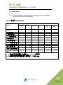
1
® X-Cite 200DC USER‟S GUIDE 2260 Argentia Road Mississauga (ON) L5N 6H7 Canada +1 905.821.2600 www.ldgi-xcite.com Printed in Canada 035-00446R Rev. 1 X-Cite® 200DC User‟s Guide 035-00446R Lumen Dynamics Group Inc. 2011 All rights reserved No part of this publication may be reproduced, transmitted, transcribed, stored in a retrieval system or translated into any language in any form by any means without the prior written consent of Lumen Dynamics Group Inc. Every effort has been made to ensure information in this manual is accurate; however, information in this manual is subject to change without notice and does not represent a commitment on the part of the authors. Trademarks X-Cite®, Intelli-Lamp®, and Closed-Loop Feedback are registered trademarks of Lumen Dynamics Group Inc. All rights reserved. All other product names are trademarks of their respective owners. Table of Contents 1 X-Cite 200DC Message Reference ....................................................................... 1 2 Introduction ............................................................................................................ 2 3 Safety ...................................................................................................................... 3 3.1 Glossary of Symbols........................................................................................... 3 3.2 Safety Precautions ............................................................................................. 4 Getting Started ....................................................................................................... 7 4.1 System Components .......................................................................................... 7 4.2 Front Panel......................................................................................................... 8 4.3 Rear panel.......................................................................................................... 9 Installation/Set-up ................................................................................................ 10 5.1 Installing Lamp Module ..................................................................................... 10 5.2 Inserting/Removing Light Guide ....................................................................... 13 5.3 Installing the Collimating Adapter ..................................................................... 15 Operation .............................................................................................................. 17 6.1 Powering Up/Powering Down ........................................................................... 17 6.2 Illuminating a Specimen ................................................................................... 18 6.3 Front Panel Button Functions ........................................................................... 18 6.4 LED Indicators .................................................................................................. 18 6.5 Display Format Reference ................................................................................ 19 6.6 Adjusting Light Output ...................................................................................... 19 6.7 Viewing Accumulated Lamp Hours ................................................................... 20 6.8 Power Measurement (Optional) ........................................................................ 20 6.9 Warnings and Alarms ....................................................................................... 22 6.10 Clearing Alarms............................................................................................. 22 Shutter Control..................................................................................................... 23 7.1 Shutter Control via Foot pedal .......................................................................... 23 7.2 Shutter control via TTL ..................................................................................... 23 Troubleshooting................................................................................................... 25 8.1 Error Codes ...................................................................................................... 25 8.2 Power Up Failure .............................................................................................. 26 8.3 Lamp Strike Failure .......................................................................................... 26 8.4 Low Light Intensity ............................................................................................ 27 8.5 Shutter Failure .................................................................................................. 27 8.6 LED Display Failure .......................................................................................... 27 8.7 Cooling Fan Failure .......................................................................................... 27 Care and Maintenance ......................................................................................... 28 9.1 General ............................................................................................................ 28 9.2 Liquid Light Guides ........................................................................................... 29 9.3 Lamps .............................................................................................................. 33 4 5 6 7 8 9 9.4 Replacing the Lamp Module ............................................................................. 35 9.5 Air Vents & Filters ............................................................................................. 36 9.6 Replacing the Air Filter ..................................................................................... 38 9.7 Replacing the External Fuses ........................................................................... 39 10 Technical Specifications ..................................................................................... 40 10.1 Electrical ....................................................................................................... 40 10.2 Environmental ............................................................................................... 40 10.3 Lamp ............................................................................................................. 41 10.4 Light Guide.................................................................................................... 42 10.5 General ......................................................................................................... 42 11 Regulatory ............................................................................................................ 43 11.1 Product Safety:.............................................................................................. 43 11.2 China RoHS .................................................................................................. 45 12 Warranty ............................................................................................................... 46 13 Contact Information ............................................................................................. 47 13.1 Replacement Parts and Accessories ............................................................. 47 Table of Figures Figure 1 Front Panel........................................................................................................ 8 Figure 2 Rear Panel ........................................................................................................ 9 Figure 3 Side Panel ....................................................................................................... 10 Figure 4 Lamp Housing ................................................................................................. 11 Figure 5 Lamp connections ........................................................................................... 12 Figure 6 Light Guide Position ........................................................................................ 14 Figure 7 Collimating Adapter ......................................................................................... 16 Figure 8 Iris Adjustment Dial Layout .............................................................................. 19 1 X-Cite 200DC Message Reference Display Message Definition XXXX. Lamp Hours Flashing: ―XXXX‖ Warming Up bulb Lamp Error cool Lamp is too hot to strike Alternating: old / bulb Alternating: end / bulb Old Lamp New Lamp Required SFI Shutter Failure E1 Lamp temperature is too high E4 Internal hardware failure E5 Failure to communicate with Intelli-Lamp E6 Lamp self extinguished E7 Internal system error Description Displays the ―hours of use‖ accumulated by the lamp The lamp is warming up. Warm up time is approximately 4 minutes ref section 6.1 Lamp installed incorrectly /Lamp did not strike. See section 8.3 The lamp will automatically strike when it has cooled to the optimum striking temperature. See section 8.3 The lamp has accumulated over 2500 hours. Lamp may be near end of life. The lamp has reached end of life. The lamp will not strike. The shutter has failed to return to home position. Unit should be restarted. If the error repeats, contact Tech Support. Check ventilation filters and outlets to ensure that no blockage exists. Restart unit and if problem persists replace lamp. If problem continues contact Tech Support Restart unit, if problem persists contact Tech Support Check Intelli-Lamp connection and restart unit. If problem persists try another lamp, if problem still persist contact Tech Support. Let system cool and restart lamp. If it goes out again, replace lamp. If new lamp continues to self-extinguish, contact Tech Support Restart unit, if problem persists contact Tech Support See Section 8 for troubleshooting. 1 035-00446R 2 Introduction The X-Cite 200DC illuminator is the ultimate combination of ease of use and performance. Like the previous X-Cite illuminators, the X-Cite 200DC has the convenience of pre-aligned, long-life Intelli-Lamps, easy installation and compatibility with all major microscope brands. With smooth 0-100% intensity control, a high speed shutter and ultra-stable lamp output, the X-Cite 200DC is an ideal choice for both routine assays and advanced imaging applications. Since 1982, Lumen Dynamics (formerly EXFO) has combined next generation optical engineering, state-of-the-art electronics and fibre-optics to produce sophisticated technologies that employ light. Today Lumen Dynamics is a leading developer of light based systems for sectors ranging from manufacturing to bio-medicine and we are unmatched in our commitment to quality and service. The X-Cite 200DC is a high quality product manufactured in accordance with ISO 9001, CE marked and certified to UL, China RoHS and CSA standards. We suggest that you read this manual to discover all its features, and how to use them. Thank you for choosing X-Cite! 2 035-00446R 3 Safety 3.1 Glossary of Symbols CAUTION - Risk of danger: consult accompanying documents WARNING -Eye damage may result from directly viewing ultraviolet light – protective eye shielding and clothing must be used at all times. Input/Output Signals Input Signal CAUTION – Hot Surface 3 035-00446R 3.2 Safety Precautions Please observe the following precautions during use. This series of cautions, warnings and dangers relate to the operation and maintenance of the X-Cite 200DC. They are also presented throughout this User’s Guide where necessary. Warning Eye damage may result from directly viewing the light produced by the lamp used in this product. Always use protective eyewear and turn the lamp off before removing cover. Caution Never look into the light emitting end of the light guide. The light could severely damage the cornea and retina of the eye if the light is observed directly. Eye shielding must be used at all times as well as clothing to protect exposed skin. Warning Always make sure the light guide is properly inserted into the X-Cite 200DC and the microscope prior to turning on power to the unit. This will minimize the risk of exposure to the UV light. Caution! To prevent damage/ degradation of the light guide, always allow adequate clearance at the front of the X-Cite 200DC unit to prevent kinking or excessive bending. Warning To reduce the risk of fire or shock, always replace the fuses with the same type and rating. Warning Disconnecting of main supply source is only possible by unplugging the power cord. Danger This unit contains HIGH VOLTAGE components. It is recommended that ONLY QUALIFIED TECHNICAL PERSONNEL perform any testing or repairs described in this manual. Disconnect the AC power cord from the unit before opening the cover of this unit. All cover screws must be replaced prior to applying power to the unit, or safety of the unit will be impaired. 4 035-00446R Monitoring the unit during manual operation The level of UV and visible energy supplied by the X-Cite 200DC is sufficient to ignite flammable substances. During manual operation, the unit must be attended at all times by a qualified operator. The unit must not be left unattended while turned on. If an operator leaves the work area of the unit, the lamp power switch must be turned off. Monitoring the unit during Automated operation The level of UV and visible energy supplied by the X-Cite 200DC is sufficient to ignite flammable substances. Therefore, when the unit is operated unattended in an automated environment, an alarm function must be provided by the user to indicate a malfunction in the associated equipment used. Warning Hg – LAMP CONTAINS MERCURY, Manage in Accord with Disposal Laws, see: www.lamprecycle.org or 1-800-668-8752 Danger: Exposure to Mercury represents a health hazard to humans. When unpacking or installing the lamp, always wear protective clothing and a face mask. Operate the lamp inside the X-Cite 200DC housing only. This prevents direct viewing of the arc and in the case of lamp bursting, contains the lamp particles. In the rare instance in which a lamp bursting occurs, and the mercury content is released, the following safety precautions are recommended; all personnel should be immediately evacuated from the area to prevent inhalation of the mercury vapour. The area should be well ventilated for a minimum of 30 minutes. Prior to clean up ensure an „approved-for-mercury‟ respirator mask and non-porous gloves such as latex or rubber are used. After the lamp housing elements have cooled, the mercury residue should be collected with the use of a special absorbing agent available from laboratory equipment suppliers. Listed below are examples of internet web sites for obtaining Mercury Spill Kits; http://www.rosshealthcare.org/Mercon.spill.kits.htm http://www.coleparmer.ca/catalog/product_index.asp?cls=43577 http://www.environmentalexpert.com/technology.aspx?idCategory=2054&word=mercury%20spill%20kits http://www.alibaba.com/products/spill_kit/4.html Warning Should this X-Cite 200DC unit be used in a manner not specified by Lumen Dynamics, the protection provided by the equipment may be impaired. 5 035-00446R Warning The method in which lamps are disposed of must comply with local rules and regulations for disposal of hazardous materials. Lamps may be returned to Lumen Dynamics providing they are returned in their original packaging. Lumen Dynamics will dispose of them in the appropriate manner. Warning This unit is designed for bench top use only! Always ensure that the unit is operated on a hard, stable surface. This will prevent obstruction of the bottom chassis ventilation openings. Any obstruction of these openings could result in a possible over-heating condition. Do not attempt to remove or tamper with the rubber feet located on the bottom of the unit. Caution The lamp module’s operational life can be significantly shortened if it is handled incorrectly. Do not touch the bulb’s glass envelope or the inside surface of the reflector. Skin oils can cause the lamp module to fail prematurely. Caution Prior to opening the unit and handling the lamp module, allow a minimum of 5 minutes for the lamp module to cool down completely. Caution Any electronic equipment connected to the X-Cite 200DC must be comply with the requirements of EN/IEC 60950. Cleaning: Clean the exterior of the unit with a slightly dampened cloth and simple water/ detergent solution only. 6 035-00446R 4 Getting Started 4.1 System Components Carefully unpack the unit and accessories. Ensure that all components are present. Store the packing material for future use. Box Contents: 1. X-Cite 200DC Illumination Unit………………………………………………………………..…… 2. Lamp Module, X-Cite 200DC (012-66000R).…………………………………………………... 3. Microscope Adapter (if ordered)…………………………………………………………………. 4. Liquid Light Guide (3mm x 1.5m or 3mm x 3.0m)……………………………………………… 5. Power Cord, IEC (shielded and grounded)……………………………………………………... 6. CD-ROM, X-Cite 200DC Manuals…………………………………………………..…………….. 7. Quick Start Guide, X-Cite 200DC…………………………………………………………………. 8. Foot Pedal Switch Assembly……………………………………………………………………… 9. Hex Key, 3mm (Lamp access cover)……………………………………………………………. If your packaged unit is missing any of the above components, call Lumen Dynamics at (905) 821-2600 or TOLL FREE 1-800-668-8752. Any additional optional items purchased to customize the unit will also be present. 7 035-00446R 4.2 Front Panel LAMP “ON” STATUS LED LED DISPLAY SHUTTER STATUS LED IRIS ADJUSTMENT DIAL LIGHT GUIDE STATUS LED LIGHT GUIDE PORT SHUTTER ACTIVATION BUTTON POWER ON/OFF SWITCH Figure 1 Front Panel 8 035-00446R 4.3 Rear panel TTL INPUT FOR SHUTTER TTL OUTPUT FOR SHUTTER SYNC AC RECEPTACLE AND FUSE DRAWER FOOT PEDAL INPUT Figure 2 Rear Panel 9 035-00446R 5 Installation/Set-up 5.1 Installing Lamp Module Note: Review Section 2 – Safety Precautions before proceeding 5.1.1 Be sure the AC POWER cord is disconnected from the unit. 5.1.2 Remove the screw from the lamp housing side panel using the 3mm hex tool provided and remove the panel from the unit cover. LAMP HOUSING SIDE PANEL Figure 3 Side Panel 5.1.3 Carefully remove the lamp module from its container, holding only the ceramic component and lamp rim. Caution! The lamp module’s operational life can be significantly shortened if handled incorrectly. Be sure only to handle the ceramic surfaces and the lamp rim. Do not touch the bulb’s glass envelope or the inside surface of the reflector. Skin oils can cause the lamp module to fail prematurely. 5.1.4 As illustrated below, position the lamp facing towards the front of the unit with the POWER leads facing towards you. The lamp should be aligned so that the leading edge of the reflector (lamp rim) fits into the mounting groove on the lamp holder assembly. 10 035-00446R LAMP HOLDER LAMP RIM POWER LEADS CERAMIC COMPONENT Figure 4 Lamp Housing 5.1.5 Make sure the middle of the lamp is in position to fit into the spring clamp. Slide the lamp until it snaps into the spring clamp. The leading edge of the reflector (lamp rim) should fit snugly into the lamp holder recess. SPRING CLAMP 11 035-00446R 5.1.6 Locate the 4-pin Intelli-Lamp sensor connector at the rear of the lamp module and connect it to its mate located on the top of the lamp-housing wall. Tip: The Intelli-Lamp connector will only attach in the correct orientation. If you are having difficulty attaching the connector, try rotating it by 180º. Note: If the Intelli- Lamp connector is not installed correctly, the lamp will not strike and the “bulb” message will display when POWER is turned on to the unit. INTELLI-LAMP CONNECTOR POWER CONNECTOR Figure 5 Lamp connections 5.1.7 Locate power connector with two leads and connect it to its mate located on the side of the lamp-housing wall. CENTER BAR AND LEAD WITHIN CUT-OUT 12 035-00446R 5.1.8 Ensure the lamp anode cooling fin (bar) and lamp power lead, at the front of the lamp, are centered within the lamp holder cut-out. Rotate the lamp as required. 5.1.9 Replace the lamp housing side panel and tighten the fastening screw. Note: If the lamp housing panel is not secured completely the lamp will not strike and the “bulb” message will display when power is turned on to the unit. 5.1.10 Replace the hex tool in the clips underneath the system for future use. Warning This unit is designed for bench top use only! Always ensure that the unit is operated on a hard, stable surface. This will prevent obstruction of the bottom chassis ventilation openings. Any obstruction of these openings could result in a possible over-heating condition. Do not attempt to remove or tamper with the rubber feet located on the bottom of the unit. 5.2 Inserting/Removing Light Guide 5.2.1 Ensure the power is not connected to the X-Cite 200DC unit. 5.2.2 Ensure that the protective end caps are removed from both the input and output ends of the light guide prior to installation. 5.2.3 Remove plastic plug (if present) from the light guide port on the front panel of the X-Cite 200DC. 5.2.4 Holding the light guide by the grey sleeve and strain relief portion only, insert the light guide into the light guide port. Push the light guide in until it seats with a second positive "click". Note: Never grip the light guide during installation or removal in a place other than the reinforced strain relief portion of the light guide. 13 035-00446R LIGHT GUIDE INSERTION LINE LIGHT GUIDE INSERTION LINE GREEN LIGHT GUIDE STATUS LED RED LIGHT GUIDE STATUS LED Figure 6 Light Guide Position Tip: When the light guide is fully inserted, the line on the light guide insertion label will be right up against the light guide port. Also, the LED above the light guide port will illuminate green when POWER is on to the unit. If the light guide is not fully inserted the LED will illuminate red. Note: The shutter will not open if the light guide is not fully inserted. 5.2.5 To remove the light guide, firmly grip the strain relief near the light guide retainer and pull out firmly. Note: The X-Cite 200DC is designed for use with a 3mm liquid light guide. Lumen Dynamics can not guarantee the performance of the X-Cite 200DC if using light guides other than those supplied by Lumen Dynamics. Note: The light guide has a minimum bend radius of 1.6 inches (40.mm). Bending or coiling the light guide tighter than this radius will result in permanent damage to the light guide. 14 035-00446R 5.3 Installing the Collimating Adapter 5.3.1 Ensure that the power is off on the X-Cite 200DC unit. 5.3.2 The existing lamp housing must be removed from the microscope before the collimating adapter can be mounted. Do not discard the existing mounting hardware, since it will be used to secure the collimating adapter to the microscope. 5.3.3 Remove the collimating adapter from its packaging. Note: The collimating adapter has been factory set. No adjustments by the customer are required; however some adapter models are outfitted with centering set screws, for longer light path applications. Separate instructions are included with these models. 5.3.4 Insert the flange portion of the collimating adapter into the lamp port of the microscope. Using the existing hardware, tighten the screw(s) until the flange is fully secured. Note: The installation of the collimating adapter will vary with microscope models. 5.3.5 Remove the protective cap from the output end of the light guide. Insert the light guide into the input portion of the collimating adapter until it is flush with the adjustable insert. Secure the light guide to the collimating adapter by tightening the thumbscrew. Do not over tighten. Note: The light guide has a minimum bend radius of 1.6 inches (40.0mm). Bending or coiling the light guide tighter than this radius will result in permanent damage to the light guide. 15 035-00446R Figure 7 Collimating Adapter Warning! Turning power to the on position without the light guide properly installed in the unit and in the microscope can increase your risk of exposure to UV light. 16 035-00446R 6 Operation 6.1 Powering Up/Powering Down Lamp Warm-Up: The ARC lamp has 3 distinct phases of operation; 1.Ignition. 2. Warm-up. Lumen Dynamics recommends 20 minutes of proper warm-up to ensure a stable optical output. 3. Stable Operation. It is recommended that phase 1 and 2 are not interrupted. This can result in shortened lamp life. The lamp must be allowed to warm-up uninterrupted. 6.1.1 Ensure that the lamp and light guide have been properly installed and that the lamp housing panel is securely fastened. 6.1.2 Plug the X-Cite 200DC unit into a properly grounded AC outlet. Warning! Turning power on to the on position without the light guide properly installed in the unit and in the microscope can increase your risk of exposure to UV light. 6.1.3 Turn on the main POWER switch ―I‖, located on the front panel and check the fan for airflow. 6.1.4 As soon as the LED display turns on, it will display the version of software currently programmed in the unit (i.e. R – X). Once the software version level has been indicated, the display will reset after several seconds to the next display mode. 6.1.5 The lamp will automatically turn on within 45 seconds and the LAMP indicator will illuminate (green). The display will flash during the warm up period for approximately 4 minutes. The display will stop flashing when the warm up period has completed. Wait until the warm up period has completed before using the unit to illuminate a specimen. Lumen Dynamics recommends 20 minutes to ensure a stable output Note: Unit should not be turned off unless the lamp has been on for a minimum of 20 minutes. 17 035-00446R 6.1.6 To power down the unit after use, set the main power switch located on the front panel to ―0‖. Note: If the lamp is turned off, and an attempt is made to turn it back on before it has fully cooled, the “Cool” message will appear on the display and the lamp indicator will be un-lit. The lamp will automatically re-strike when the lamp has cooled, the lamp indicator will illuminate (green). 6.2 Illuminating a Specimen 6.2.1 When the X-Cite 200DC is first powered on, the internal shutter will be in the closed position as a safety precaution. If the shutter is not closed error code SFI will appear on the LED display. 6.2.2 To illuminate a specimen, press and release the SHUTTER button to open the shutter (OPEN LED will turn on). 6.2.3 Use “Iris Adjustment Dial” for intensity adjustment to desired level. 6.2.4 Press the SHUTTER button to close the shutter. The OPEN LED will turn off. 6.3 Front Panel Button Functions Button Condition Description I/O Press on press off Turns unit on ―I‖ Turns unit off ―0‖ SHUTTER Press and release Opens/closes internal shutter 6.4 LED Indicators LED Indicator LIGHT GUIDE LAMP OPEN Status On – green On – red Description The light guide is fully inserted The light guide is not fully inserted On - green The lamp is on Off – no illumination The lamp is off On - green Off – no illumination The shutter is open The shutter is closed 18 035-00446R 6.5 Display Format Reference 6.5.1 The formatting used on the display board is used to identify the unit of measurement or phase of operation. Display Format Definition Description XXXX. Lamp Hours Displays the ―hours of use‖ accumulated by the lamp Warming Up The lamp is warming up. Warm up time is approximately 4 minutes Flashing: ―XXXX‖ 6.6 Adjusting Light Output Figure 8 Iris Adjustment Dial Layout 6.6.1 To adjust light intensity, use the Iris Adjustment Dial and set to desired level by turning. Clockwise to increase light intensity and counter-clockwise to decrease light intensity. 6.6.2 There are no detent stops, motion is smooth starting from 0% and ending at 100%. 0, 12.5, 25, 50, 100% are marked on the fascia around the dial for reference (ref. Figure 8) 6.6.3 Note that as the lamp ages, absolute power at a given setting will decrease. Adjust the intensity as necessary. If monitoring absolute value of lamp output is desired, refer to section 6.8 or contact Lumen Dynamics about purchasing an XCite Optical Power Measurement System (OPMS). 19 035-00446R 6.7 Viewing Accumulated Lamp Hours 6.7.1 The X-Cite 200DC system automatically accumulates the number of hours for which the lamp has been on by saving it to the Intelli-Chip on the lamp, and shows this information on the LED display. The lamp hours are shown when the unit is powered on and after lamp has warmed up. 6.8 Power Measurement (Optional) 6.8.1 If your X-Cite 200DC was purchased with the X-Cite Optical Power Measurement System accessory, power output can be measured at the end of the light guide using the XR2100 or at the specimen plane using the XP750. Note: To learn more about the OPMS or to purchase the OPMS accessory contact Lumen Dynamics. XR2100 Optical Power Meter with Light Guide Input; 1. Install the supplied light guide adaptor corresponding to the size of your light guide into the Optical Input Port of the XR2100 2. Ensure the X-Cite 200DC shutter is closed and set Iris to the desired intensity level. 3. Remove light guide from microscope adapter and insert the light guide end into the light guide adaptor and fasten in place using the supplied thumb screw. 4. Open shutter and turn the XR2100 to ON. 5. Use Relative/Absolute button on the XR2100 to adjust display mode of measurement. XP750 Objective Plane Power Meter Sensor (with upright microscopes); 1. Plug the XP750 multi-pin connector into the XR2100, turn the XR2100 to ON. 2. Place the XP750 onto the stage with the detection window facing up, and approximately centered beneath the microscope objective lens. 3. Secure the XP750 in place using the microscope’s stage clip and the supplied suction-cup ensuring the XP750 is seated firmly and sits flush on the stage. 4. Turn on the epi-fluorescence light source and open the microscope shutter, ensure that the filter cube in the beam path is directing visible light to the microscope stage 20 035-00446R 5. To align the detection window with the visible light from the microscope objective, use the microscope stage x-y controls, ensuring the light is centered within the window. 6. Engage the appropriate objective, filter cube, intensity and other microscope settings and press the „(nm)‟ button on the XR2100 to see the current wavelength setting. XP750 Objective Plane Power Meter Sensor (with inverted microscopes); 1. Plug the XP750 multi-pin connector into the XR2100 turn the XR2100 to ON. 2. Place the XP750 onto the stage with the detection window facing down, and approximately centered beneath the microscope objective lens. The + icon (etched inside a circle) should be facing up which marks the center of the detection window. 3. Secure the XP750 in place using the microscope’s stage clip and the supplied suction-cup ensuring the XP750 is seated firmly and turn on the transmission light source and using the microscope stage x-y controls, center the light on the + icon. 4. Engage the appropriate objective, filter cube, intensity and other microscope settings and press the „(nm)‟ button on the XR2100 to see the current wavelength setting. Note: To learn more about the OPMS or to purchase the OPMS accessory contact Lumen Dynamics. 21 035-00446R 6.9 Warnings and Alarms 6.9.1 The X-Cite 200DC is designed to detect certain conditions that may affect safe or proper functioning. These conditions are categorized as one of two ―alarm types‖ according to the danger they pose to the operator, system or experiment: 1. Critical Safety – continuing may cause harm to the operator or equipment, alarm is an audible 3 beep ―Alarm Condition‖. 2. Function – operation may continue, but depending on specific alarm condition, functionality of unit may be limited or impossible (e.g. lamp too hot to strike) Alarm Condition Alarm Type Other Actions/ Corrections Light guide is not inserted properly and/or removed while shutter is open or an attempt is made to open the shutter LIGHT GUIDE LED turns red, ―3 beep‖ audible alarm Critical Safety Shutter shall automatically close and be disabled from opening until light guide is inserted Lamp failure to strike Display ―BULB‖ Function Lamp too hot to strike Display ―CooL‖ Function Shutter failure ―3 beep‖ audible alarm display ―SF1‖ Lamp overheated ―3 beep‖ audible alarm. Display ―E1‖ Lamp self-extinguish or nonpassive failure ―3 beep‖ audible alarm. Display ―E6‖ Automatically attempts to re-strike lamp when cool Critical Safety If failure to close—lamp turns off Critical Safety Lamp turns off Critical Safety Fan/blower shall shut off 6.10 Clearing Alarms 6.10.1 The X-Cite 200DC provides an audible alarm (3 beeps only) to alert the operator of various error conditions. After the 3 beeps have counted off, the alarm will automatically shut off. 22 035-00446R 7 Shutter Control 7.1 Shutter Control via Foot pedal 7.1.1 For hands-free operation, the X-Cite 200DC is equipped with a foot pedal. The foot pedal is an alternative to the SHUTTER button and can only be used to open and close the internal shutter. To use the foot pedal: 1. Plug the foot pedal into the 3.5mm audio style port labelled FP on the back on the X-Cite 200DC. 2. Place the foot pedal on the floor or another conveniently located flat surface. 3. Power-up the X-Cite 200DC as normal, and wait for the lamp to warm up. 4. Press down on the foot pedal until it clicks to open or close the shutter. 7.2 Shutter control via TTL 7.2.1 For high-speed shutter activation, TTL control can also be used. The plot below shows typical timing values for the X-Cite 200DC internal shutter when controlled by TTL. Note that these values should be used as a guide only, and that actual values will vary slightly from unit to unit. t3 TRIGGER t1 RESPONSE SHUTTER RESPONSE t2 t4 t5 80% SYNC. O/P SYNC OUTPUT Interval t1 t2 t3 t4 t5 Description Delay time, trigger to start of opening Start of opening to 100% open Minimum recommended exposure time (trigger open to trigger close) Delay time, trigger to start of close Start of close to 0% open Time (milliseconds) 4 2 40 4 2 Note: Using values of t3<40ms may result in shutter bounce-back and a brief unintentional exposure period. 23 035-00446R TTL Signal and Shutter Status TTL Shutter Sync high low open closed low high TTL INPUT (BNC) Maximum low-level +0.8VDC Minimum high-level +2.0VDC Maximum high-level +5.5VDC Typical input current: 800uA SYNC OUT (BNC) Maximum low-level +0.8VDC Minimum high-level +4.5VDC Maximum output current: 500uA 24 035-00446R 8 Troubleshooting Service to be completed by qualified repair personnel only! 8.1 Error Codes If the X-Cite 200DC internal monitoring systems identify a problem, an error code will be generated. Definitions and recommended actions are in the following table. Code Error Description E1 Lamp temperature is too high E4 Internal hardware failure E5 Failure to communicate with Intelli-Lamp E6 Lamp self-extinguished E7 Internal system error bulb Lamp Error cool Lamp is too hot to strike Alternating: old / bulb Alternating: end / bulb SFI Old Lamp New Lamp Required Shutter Failure Recommended Action Check ventilation filters and outlets to ensure that no blockage exists. Restart unit and if problem persists replace lamp. If problem continues contact Tech Support. See also section 8.7 Restart unit, if problem persists contact Tech Support Check Intelli-Lamp connection and restart unit. If problem persists try another lamp, if problem still persist contact Tech Support. Let system cool and restart lamp. If it goes out again, replace lamp. If new lamp continues to self-extinguish, contact Tech Support Restart unit, if problem persists contact Tech Support Lamp installed incorrectly /Lamp did not strike. The lamp will automatically strike when it has cooled to the optimum striking temperature The lamp has accumulated over 2500 hours. Lamp may be near end of life. The lamp has reached end of life. The lamp will not strike. The shutter has failed to return to home position. Unit should be restarted. If the error repeats, contact Tech Support. 25 035-00446R 8.2 Power Up Failure If the unit fails to POWER up or function properly, use the following checklist to eliminate the most common causes of problems. Check that: 1. The AC POWER cord is securely plugged into a functional AC wall plug. 2. The AC POWER cord is securely plugged into the AC inlet on the rear of the unit. 3. The main AC POWER switch is in the ON position. 4. Check that the ventilation openings on both the bottom and rear of the unit are not blocked. If the unit still does not power-up: 5. Check both main power fuses by first disconnecting the power cord. Then carefully remove the fuse drawer assembly below the AC inlet on the rear of the unit. If the fuse(s) is/ are open, replace with the same type (5A, 250 V, Fast acting). 8.3 Lamp Strike Failure If the LED display lights and the fan starts, but the lamp will not turn on, check for the following: 1. The LED display indicates the ―bulb‖ message and the system begins to beep. This indicates that no lamp is detected. Check if the lamp has been installed correctly. Refer to section 5.1– Installing the Lamp Module. 2. The LED display indicates the ―bulb‖ message after approximately 45 seconds and the system will beep 3 times as an audible warning. This indicates that the lamp has failed to strike. It may be a result of the lamp reaching end of life, or that the lamp housing panel is not secured properly in place. Press the MODE button to clear the audible alarm. Turn power off to the unit. Check that the lamp housing panel is secured properly. Wait a few minutes and turn the power on to the unit. If it still does not strike, replace the lamp. 3. The LED display indicates the ―Cool‖ message. This indicates the lamp is too hot to strike. The lamp will automatically strike when it has cooled. 26 035-00446R 8.4 Low Light Intensity If the light intensity is too low, check that: 1. The percent iris opening is set high enough, if not turn Iris Adjustment Dial to a higher setting. 2. There are no foreign substances on the emitting end of the light guide. 3. There are no bends, kinks, or other physical damage to the guide. Replace the light guide if there is any physical damage. 4. The lamp has been installed correctly. See section 5.1– Installing the Lamp Module. 5. Check the microscope settings, filter cubes, ND filters, manual stops, polarisers, and position of camera port beam splitters for anything that may be blocking the light path between the X-Cite and eyepieces/camera. It may be necessary to replace the lamp or to replace the light guide. Contact your Lumen Dynamics sales representative for information on purchasing a new lamp or light guide. 8.5 Shutter Failure If the shutter does not open, check that: 1. The light guide is fully inserted; the LED above the light guide port will be illuminated green. The lamp is warmed-up; the display is not flashing. The iris setting is not at 0%. 2. If the LED displays “SF1‖, indicating a shutter failure. POWER down the unit, wait a few minutes and turn POWER on to the unit. If the unit displays a shutter failure again, contact your local Lumen Dynamics Service Center to have your unit serviced. 8.6 LED Display Failure If the LED display does not light: 1. If the fan is functional, POWER down the unit, wait approximately 20 seconds then POWER it up again. 2. If the problem persists, contact your local Lumen Dynamics Service Center. 8.7 Cooling Fan Failure If one or more fans do not work: 1. If the LED display is functional, POWER down the unit, wait approximately 20 seconds then POWER it up again. 2. If the problem persists, contact your local Lumen Dynamics Service Center. 27 035-00446R 9 Care and Maintenance 9.1 General This section contains installation, maintenance and troubleshooting tips to help optimize the lifetime and performance of X-Cite 200DC units and components. This information is intended to supplement the detailed installation and operating instructions found in the X-Cite User Manuals. Topics covered include liquid light guides, lamps, and air vents – the components most likely to affect performance over time and require maintenance or replacement. Note that the lifetime information on components is for typical or average conditions. Depending on the imaging application, more frequent replacement may be required—for example, if a fluorophore’s signal is low to begin with, or is excited by a low power portion of the X-Cite 200DC lamp’s output spectrum. 9.1.1 Operate the unit in a well ventilated area with at least six inches clearance at the rear of the unit for proper air flow. Do not place any objects below the unit, between the feet as this will restrict airflow through the bottom of the front face plate. 9.1.2 For safe operation, use only a grounded outlet. 9.1.3 Avoid physical shocks or jarring to the unit especially while the unit is operating. Such sudden movements reduce the lamp module life. 9.1.4 The lamp module must be operated for a minimum of 20 minutes each time it is turned on to prevent damaging the lamp. Increasing the time between turning the lamp module on and off will maximize lamp life. 9.1.5 Replace the air filter, found under the front face plate, frequently to ensure unrestricted air flow. It is recommended as a minimum that the air filter be replaced every time the lamp module is replaced. Note: restricted airflow can cause the lamp temperature to increase above optimum temperature, significantly reducing lamp life. 9.1.6 When necessary, clean the light emitting end of the light guide using an optical cleaning solution. 9.1.7 Cleaning of unit is not required, however if cleaning is desired, disconnect the AC power cord from the unit and use only a water and simple detergent solution. Ensure that cleaning solution does not come in contact with any optical, moving mechanical or electrical parts. 28 035-00446R 9.2 Liquid Light Guides Tips to Prevent Premature Degradation of Light Guides 9.2.1 Liquid light guides have a typical useful life of 2-3 years/4000 operational hours in the X-Cite 200DC when installed and handled properly. The formation of bubbles is one of the most common reasons for a light guide to degrade prematurely and result in a sudden reduction in illumination intensity. Bubbles form without warning, usually due to overheating and/or mechanical stress to the light guide. Below are some simple tips to avoid overheating and stressing the light guide. 9.2.2 The light guide has a minimum bend radius of 1.6 inches (40.0mm) however, a bend radius of at least 75mm is recommended for a light guide while ―in use‖. Sharper bends can cause heat to build up and cause problems longer term. Bending or coiling the light guide tighter than this radius will result in permanent damage to the light guide. Minimum bend radius to prevent immediate damage to the LLG is 40mm,. 9.2.3 Make sure the light guide is cooled properly during use, and prevent overheating: a. Always fully insert the light guide in to the X-Cite 200DC; this ensures contact with a heat sink to conduct heat away from the light guide. b. Never obstruct the air vents on the X-Cite 200DC. Vents are located at the rear and underside of the unit. c. Do not remove the rubber feet on the X-Cite 200DC or otherwise reduce/block the space between the bottom of the unit and bench top. This may compromise airflow through the unit. d. Ensure that the air being used to ventilate the X-Cite 200DC is approximately ―room temperature‖ (e.g. do not place the X-Cite unit on top of another heatproducing instrument). e. If a heated environmental chamber is being used for live cell imaging, make sure that the X-Cite 200DC and the light guide are located outside of the chamber. 9.2.4 Do not expose the light guide to extreme temperatures (above 35°C, below -5°C) for extended periods of time during use, transport or storage; this may cause degradation of the seals and allow air bubbles to form in the liquid. 9.2.5 Never kink, bend, crush, or stretch the light guide; this type of mechanical stress may cause bubbles to form in the liquid and/or damage to the outer sheath a. Always allow adequate clearance between the light guide port of the X-Cite 200DC and other objects to prevent excessive bending. b. Place the X-Cite 200DC close enough to the microscope so that there is some slack in the light guide and no sharp bends. 29 035-00446R 9.2.6 Never leave an endcap on the output end of the light guide when the other end is connected to the X-Cite 200DC; if the unit is turned on in this condition, the cap will overheat, melt and/or permanently discolour the quartz end of the light guide. 9.2.7 While the X-Cite 200DC is on but not in actual use (i.e. during sample preparation, or between time lapse time points) close the iris/shutter on the XCite; this reduces unnecessary UV photon load on the liquid light guide. (Using only the shutter/stop in the microscope itself protects the specimen, but energy is still passing through the light guide.) Proper handling and installation of liquid light guides 9.2.8 Liquid light guides have a typical useful life of 4000 hours of operation when handled properly and installed in a well maintained X-Cite 200DC. The formation of bubbles is one of the most common reasons for a light guide to degrade prematurely and result in a sudden reduction in illumination intensity. Bubbles can form without warning, and if they occur within the first 1500 to 2000 hours of use, is it typically due to overheating and/or mechanical stress to the light guide. Below are some simple tips to avoid overheating and stressing the light guide; 9.2.9 Always fully insert the light guide in to the X-Cite 200DC (refer to section 5.2); this ensures contact with a heat sink to conduct heat away from the light guide. 9.2.10 Always place the X-Cite 200DC close enough to the microscope so that there is some slack in the light guide and no sharp bends. 9.2.11 Never leave an endcap on the output end of the light guide when the other end is connected to the X-Cite 200DC; if the unit is turned on in this condition, the cap will overheat, melt and/or permanently discolour the quartz end of the light guide. 9.2.12 Do not expose the light guide to extreme temperatures (above 35°C, below -5°C) for extended periods of time during use, transport or storage; this may cause degradation of the seals and allow air bubbles to form in the liquid. 30 035-00446R What does a bubble look like? 9.2.13 Depending on the size and location in the light guide, a bubble may or may not be obvious. To check for bubbles: 9.2.14 Disconnect the LLG from the X-Cite 200DC and microscope adapter. 9.2.15 Hold one end towards a bright window or overhead room light - DO NOT use an X-Cite 200DC or any other focused light source for this test! 9.2.16 Look at the quartz at the other end of the LLG a. Bubble-free: quartz end will appear as a bright, solid circle; you may also be able to see a thin circular outline at the quartz/liquid interface. b. Bubbles at/near the quartz end: appear as dark spots, as small as 0.5mm in diameter or even as larger more defined spheres. c. Bubbles in the middle of the light guide: may not be well-defined spots, but will appear as dark shadows. d. In extreme cases, where the bubble is blocking the entire diameter of the light guide, no light will come through, even when pointing the distal end at a light source. 100% 11.3% 5.2% Appearance and % output of light guides with bubbles relative to an LLG without bubbles (100%). 31 035-00446R Can a bubbled light guide recover? 9.2.17 Yes, light guides with small bubbles can sometimes recover. Disconnect the light guide from the X-Cite 200DC, and leave the light guide undisturbed on a shelf for 1-2 weeks. For this to be effective, it is important to catch the bubble when it is small. When should light guides be replaced? 9.2.18 It is usually time to replace a light guide when: 1. Illumination is low and replacing the lamp does not improve brightness 2. Dark or uneven areas become visible in the field of view (a bubble is blocking part of the light) 3. A section of the light guide becomes noticeably warmer than the rest of the guide (a bubble is blocking transmission of light, forcing the light guide to absorb the energy) 4. It is 2-3 years old OR has been in use for 4000-6000 hours (2-3 lamp changes) 32 035-00446R 9.3 Lamps Spectrum and lifetime 9.3.1 The lamp output and typical output levels over lifetime are shown below. Lamp Output Spectrum X-Cite 200DC 33 035-00446R 9.3.2 It is normal for the output to decline over the first several hundred hours of use and then stabilize at a level ~70% of the initial output for the remainder of the lamp life. If the lower power regions of the output spectra are being used, it may be desirable to replace lamps more frequently to maximize signal levels. X-Cite 200DC Lamp: Typical Degradation 34 035-00446R General tips to help maximize lamp lifetime: 1. Each time the lamp is ignited, the stress on the lamp effectively decreases lamp life by 5 hours, therefore it is recommended to avoid shutting down the unit during lunch or short breaks or between users, if being used in a multi-user lab 2. After lamp ignition, avoid turning the lamp off until it has run for a minimum of 20 minutes 3. Avoid attempting to strike a hot lamp (note: the X-Cite 200DC Intelli-Lamp will prevent this) 4. Avoid unnecessary movement and jarring of the lamp, especially when it is in operation or hot. 5. When changing a lamp: a. Handle the lamp only by the ceramic areas b. Never touch the glass envelope of the bulb (inner stem), the inner surface, or the outer surface of the reflector. If touched, carefully clean the envelope with alcohol. Skin oils can etch the glass and cause premature bulb failure c. Wear cotton gloves or powder free latex/nitrile gloves when handling any lamp 6. Ensure that air filters are kept clear of dust and debris – even a partially blocked filter can reduce lamp lifetime to approximately 25% of what is normally expected. 9.4 Replacing the Lamp Module 9.4.1 The X-Cite 200DC is designed to operate only with the X-Cite 200DC lamp module supplied by an authorized Lumen Dynamics distributor. When the lamp requires replacing, use only: Lumen Dynamics Part # 012-66000R Description X-Cite 200DC/exacte replacement lamp module Refer to section 5.1 for lamp module replacement instructions Refer to section 8 for messages regarding troubleshooting and lamp module replacement. Refer to section 3.1 Glossary of Symbols, for lamp warning information. Refer to section 6.1 Powering Up/Powering Down, powering up/down instructions. 35 035-00446R 9.5 Air Vents & Filters 9.5.1 X-Cite 200DC has several air vents that are an integral part of the cooling system and overall lamp performance. Proper cooling ensures that lamps operate at optimal temperature and pressure for output power, spectrum, lamp life, light guide life and safety. Ensuring adequate cooling 9.5.2 Never obstruct the air vents on the X-Cite 200DC. Vents are located at the rear and underside of the unit. 9.5.3 Always leave clearance for air flow between the X-Cite 200DC and walls or other equipment. Do not remove the rubber feet on the X-Cite 200DC unit or otherwise reduce/block the space between the bottom of the unit and bench top. This may compromise airflow through the unit. 36 035-00446R 9.5.4 Ensure that the air being used to ventilate the X-Cite 200DC is approximately ―room temperature‖ (e.g. do not place the X-Cite 200DC on top of another heatproducing instrument). 9.5.5 If a heated environmental chamber is being used for live cell imaging, make sure that the X-Cite 200DC and the light guide are located outside of the chamber. 9.5.6 Periodically check the air filter at the air intake vent for debris. Replace or clean as necessary 37 035-00446R How to Check/Clean Metal Vents 9.5.7 When unit is OFF and lamp is COOL, unplug power from X-Cite 200DC and turn unit upside down. Visually inspect the metal gratings for lint, dust and other debris. 9.5.8 Debris can be removed from the gratings using a small vacuum cleaner with a crevice tool, or blown out with a can of compressed air. If using compressed air, direct the air flow ACROSS the vents, not perpendicularly (i.e. into the X-Cite 200DC). 9.6 Replacing the Air Filter 9.6.1 The external air filter is located under the front face plate of the X-Cite 200DC. 9.6.2 Turn off the main POWER switch and remove the AC POWER cord from the unit. 9.6.3 Gently slide and pull out the filter. 9.6.4 Push in the replacement filter so that it sits flat in place What happens if filters and vents are not clean? 9.6.5 A complete filter blockage or airflow obstruction generally results in an automatic lamp shutoff within 10-15 minutes of the unit being powered on due to lack of adequate cooling. 9.6.6 A partially clogged filter may allow enough airflow for continued operation, but not for optimal cooling. In this case, the result is usually dramatically reduced lamp life, e.g. 400 hours instead of 2500+ hours. 38 035-00446R 9.7 Replacing the External Fuses 9.7.1 The external (main) fuses are located in the fuse drawer which is located in the AC inlet module on the rear panel. 9.7.2 Turn off the main POWER switch and remove the AC POWER cord from the unit. 9.7.3 Gently pull out the drawer with the aid of a flat-head screwdriver. 9.7.4 Carefully lever one end of each fuse up from its retaining clip with a small flathead screwdriver and lift it out. 9.7.5 Replace the blown fuse(s) only with the same type and rating (F5A, 250V). The rear compartment must contain two active fuses. 9.7.6 Close the fuse drawer. 9.7.7 Reconnect the AC POWER cord. 39 035-00446R 10 Technical Specifications 10.1 Electrical Power Supply: Power Factor Corrected, Universal Input Input Voltage: 100 - 240VAC, 50/60Hz Current: 3.5A max at 120VAC 2.0A max at 240VAC Input Surge: 50A max. (cold start) Protection: Power supply: Short circuit protection Overvoltage protection: 30-50% above nominal output Overload protection: 110-160% of normal rating Fuse Rating: Dual fuse system: each fuse rated at F5.0A 250V, 5x20mm type located in the AC receptacle 10.2 Environmental Operating Conditions Ambient Temperature: 15ºC to 40ºC Altitude: 2000m max. Atmospheric Pressure: 700 to 1060 hPa Relative Humidity: 15% to 95% (non-condensing) Installation Category: II Pollution Degree: 2 Enclosure Rating: IPXO Transport and Storage Conditions Temperature: -40 to +70ºC Relative Humidity: 10% to 100% Atmospheric Pressure: 500 to 1060 hPa 40 035-00446R A B 10.3 Lamp C E D A - Rim of Lamp Reflector . B - Reflector. C - Back Ceramic Mount D - Intelli-Lamp Connector. E - Power Connector Lamp Module Lumen Dynamics 200W Arc Lamp Lamp Module Life 2000 hours Warm Up 20 minutes (min), reference sections 3.1 Glossary of Symbols and 6.1 Powering Up/Powering Down. CAUTION: Use only Lumen Dynamics lamp part number 012-66000R in the X-Cite 200DC unit. 41 035-00446R 10.4 Light Guide Light Delivery Flexible liquid filled light guide 1.5m or 3m in length with a core diameter of 3mm. Custom light guides are also available. Liquid Light Guide End Fitting Liquid Light Guide Dimensions in mm Core d0 3 End Fitting d1 5 End Fitting Radius d2 9 Minimum Bend (mm) 40 Transport and Storage Conditions Temperature: -5°C to 35°C Note: Refer to section 9.2 for tips on maintaining liquid light guides in good working condition. 10.5 General Height : Depth: Width: Weight: 8.2" / 20.6cm 13.3" / 33.8cm 7.1" / 18.0cm 10.8lbs / 4.9kg Note: X-Cite 200DC unit dimensions only, does not include clearance at front of unit for liquid light guide. 42 035-00446R 11 Regulatory 11.1 Product Safety: EN/ IEC 61010-1:2001 Safety Requirements for electrical Equipment for Measurement, Control and Laboratory Use- Part 1: General Requirements CAN/CSA C22.2 No. 61010-1-04 Safety Requirements for Electrical Equipment for Measurement, Control and Laboratory Use Part 1: General Requirements UL 61010-1: 2004 2nd Edition Safety Requirements for Electrical Equipment for Measurement, Control and Laboratory Use Part 1: General Requirements IEC Equipment Class: I Installation Category: II Pollution Degree: 2 Electromagnetic Compatibility: EN 61326-1: 2006/ IEC 61326: 2002 Immunity Testing-Electrical Equipment for Measurement, Control and Laboratory Use-EMC Requirements, Part 1 CISPR 11 :2004/EN 55011 :1998 + A1 & A2 FCC Part 15, Subpart B, Class A Emissions TestingClass A, Group 1, Industrial, Scientific & Medical Equipment Unintentional Radiators CE Marking: Council Directive 73/23/EEC Low Voltage Directive Council Directive 89/336/EEC EMC Directive Council Directive 2002/96/EC WEEE Directive 43 035-00446R FCC Class A Digital Device or Peripheral - Information to User NOTE This equipment has been tested and found to comply with the limits for a Class A digital device, pursuant to Part 15 of the FCC Rules. These limits are designed to provide reasonable protection against harmful interference when the equipment is operated in a commercial environment. This equipment generates, uses, and can radiate radio frequency energy and, if not installed and used in accordance with the instruction manual, may cause harmful interference to radio communications. Operation of this equipment in a residential area is likely to cause harmful interference in which case the user will be required to correct the interference at his own expense. WARNING Changes or modifications not expressly approved by Lumen Dynamics could void the user’s authority to operate the equipment. WEEE Directive (2002/96/EC) The symbol above indicates that this product should not be disposed of along with municipal waste, that the product should be collected separately, and that a separate collection system exists for all products that contain this symbol within member states of the European Union. The equipment that you bought has required the extraction and use of natural resources for its production. It may contain hazardous substances that could impact health and the environment. In order to avoid the dissemination of those substances in our environment and to diminish the pressure on the natural resources, we encourage you to use the appropriate take-back systems. Those systems will reuse or recycle most of the materials of your end life equipment in a sound way. The crossed-out wheeled bin symbol indicated above invites you to use those systems. If you need more information on the collection, reuse and recycling systems, please contact your local or regional waste administration. 44 035-00446R 11.2 China RoHS 11.2.1 The following table contains substance information for the X-Cite 200DC as required by the China RoHS regulations. 有毒和危险物质或元素的名称及内容 有毒和危险物质或元素 部件名称 弧光灯组件: (200瓦) Pb(铅) Hg(汞) Cd(镉) Cr6+(铬6 +) PBB(多溴 化二苯) PBDE(多溴 化二苯脂) o X o ○ ○ ○ 激发组件(密封的) o ○ ○ ○ ○ ○ 缓冲器印刷电路板装配 o ○ ○ ○ ○ ○ 灯具镇流器印刷电路板装配 o ○ ○ ○ ○ ○ 电源印刷电路板装配 o ○ ○ ○ ○ ○ 光阑定位印刷电路板装配 o ○ ○ ○ ○ ○ 正面板/显示器印刷电路板装配 o ○ ○ ○ ○ ○ 输入/输出信号印刷电路板装配 o ○ ○ ○ ○ ○ 挡板驱动印刷电路板装配 o ○ ○ ○ ○ ○ 挡板定位传感器印刷电路板装配 发光二极管模式显示器印刷电路 板装配 o ○ ○ ○ ○ ○ o ○ ○ ○ ○ ○ ○:表示该部件所有的同质材料中有毒或危险物质含量低于SJ/T11363-2006标准的限制要求。 x:表示该部件中至少有一种同质材料中有毒或危险物质含量高于SJ/T113632006标准的限制要求(企业可以在该表格中对基于实际情况所标注的―X‖进一步做技术上的解释。) 45 035-00446R 12 Warranty Lumen Dynamics warrants the original purchaser for a period of one (1) full year, calculated from the date of purchase, that the equipment sold is free from defects in material and workmanship. In the event of a claim under this guarantee, the equipment is to be sent postage and carriage paid, including a description of the fault, to the Lumen Dynamics Service Center. Returned equipment will not be received without a Return Authorization (RA) Number, issued by the appropriate Service Center. In the case of damage caused by wear and tear, careless handling, neglect, by the use of force or in the case of interventions and repairs not carried out by a Lumen Dynamics Service Center, the guarantee ceases to be valid. This guarantee may not form the basis for any claims for damages, in particular not for compensation of consequential damages. The warranty is not transferable. No warranty is extended to perishable items, such as fuses, air filters and light guides. Any claims for units received with defects in material or workmanship must be reported to an authorized Lumen Dynamics Service Center within 30 days from the original date of receipt. Replacement Bulb Warranty If the X-Cite 200DC bulb fails to strike during the warranty period of 2000 hours, the bulb will be replaced under warranty, or a credit will be applied to the purchaser’s account. In the event of a claim under this guarantee, the lamp is to be sent postage and carriage paid, including a description of the fault, to the Lumen Dynamics Service Center. Returned equipment will not be received without a Return Authorization (RA) Number, issued by the appropriate Service Center. Lamps must be purchased from an authorized Lumen Dynamics Representative or Distributor to be eligible for the warranty replacement. This warranty is nontransferable. In the case of damage caused by careless handling, neglect, by the use of force or in the case of interventions and repairs not carried out by a Lumen Dynamics Service Center to the X-Cite 200DC system, the guarantee ceases to be valid. Returning equipment to Lumen Dynamics 1. Please make a note of the problem encountered, the steps followed to isolate the problem and the result of any trouble shooting steps taken. 2. Contact the nearest Lumen Dynamics Service Center to obtain a Return Authorization Number. For your convenience, RA numbers can also be requested on-line at: http://www.ldgi-xcite.com/support-need-serviced.php 46 035-00446R 3. Follow shipping instructions provided by the service technician. The unit should be returned in its original packaging if possible. Please do not ship the unit with the lamp installed. 13 Contact Information Lumen Dynamics Tel: (905) 821-2600 Fax: (905) 821-2055 1-800-668-8752 (USA and Canada) [email protected] www.ldgi-xcite.com www.ldgi-xcitestore.com 13.1 Replacement Parts and Accessories Replacement parts and accessories can be purchased directly from Lumen Dynamics. For ordering and pricing information contact the inside sales department at: [email protected] www.ldgi-xcite.com 1-800-668-8752 Part Number Description 010-00283R X-Cite 200DC Illumination System 012-66000R X-Cite 200DC/Exacte Lamp Module 805-00038 X-Cite Liquid Light Guide 3mm x 1.5m 805-00040 X-Cite Liquid Light Guide 3mm x 3.0m 622-00012R Replacement Air Filter 850-00023R Hex Key, 3mm (lamp access cover) 031-00034R X-Cite 200DC CD Users guide 035-00447R X-Cite 200DC Quick Start English 010-00245R Optical Power Measurement System includes; - X-Cite XR2100 Optical Power Meter (010-00242R) - X-Cite XP750 Objective Plane Power Sensor (010-00241R) 47 035-00446R