1
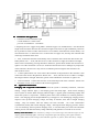
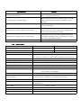
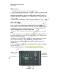
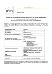
Solar charge controller
User's Manual
I main characteristics
1. Adopting the single chip and special software on the basis of expert control system , realized
the Intelligence Optimization SOC control .
2. Adopting External temperature transmitter to compensate temperature , much precise than
internal temperature transmitter
3. Automatic protect against over charge , over discharge , electronic circuit , overload , all these
protections do not bring any harm to any component , not burn the fuse wire .
4. Taking series connection PWM charge as the main circuit , saving half charging loop voltage
than using the the diode charge .
5. LED shows the battery condition ,users can get the service state directly ,
6. All the control adopt Industry-specific chip , can running free under any cold , hot , humid
circumstance .
7. Adopting audio-visual double LED to show the settings , complete all operating and Settings
by one press button , time alarm and figure display correspond to each other .
8. Making full use of the advanced power source technology , Greatly improved the effective
power of unit area, much more compact structure.
9. The large diameter, big interval terminals, can install 6 mm2 conducting wire , wire interval is
9.5 mm, can enhance the isolation and the installation reliability, wires hard to slipping .
II system specification
This controller designed for solar energy power supply system, dc solar energy lamp system , and
use a special computer chip intelligent controller, complete all operating and Settings by one key
type light touch switch. With the protection against short circuit, overload, unique meter protector
against fraud , automatic shutoff when over charge , over discharge , resume and some other protective
measures , detailed instructions, battery charging state, load and various kinds of fault instructions.
This controller takes samples according to the battery voltage, current, environment temperature
battery capacity by the computer chip , through the special control model calculation, realize the
discharge rate conform to battery characteristics. Temperature compensation of high efficiency, high
accuracy fixed control, used the efficient battery charging mode PWM, ensure the battery in the best
working state , greatly extend the service life of the battery. Has a variety of work patterns, output
model selection, can meet the needs of various users .
III installation and application
1. Controller's fixation should be rigid
overall dimension: 164*97.5mm
pore size of installation : 154*60mm
2. Preparing the wire: suggest using Multi---Strands Copper Core Insulated Wire . First decide the
length of the wire,then decrease the connection length on the basis of right installation position as
far as possible in order to reduce electrical loss. In accordance with electrical current density is no
more than 4A/mm2 to choose the cross--sectional area of copper wire, and strip the controller side
of the lug's insulation about 5mm.
3. First, connect the terminals of the battery in the controller, then connect the other ends to the
battery.Please note + - level, and don't reverse. If the connection is right, the indicator will light,
which can be examined by pressing the button. Otherwise, please check whether the connection is
right or not. If the connection is reverse, it would not burn the fuse wire or damage any component
of the controller. The fuse wire only used as an ultimate protection against the controller own
internal short circuit .
4. Connect photovoltaic wire. First connect the terminals of the photocell in the controller , then
connect the other ends to the photocell. Please note + - level, and don't reverse. If there is sunlight,
the charge indicator will light. Otherwise, please check whether the connection is right or not.
5. Load connection . Connect the load wire to the load output end of the controller . Please note
+ - level,don't reverse, so as not burn with electrical appliances.
IV Application instructions
Charging and overpressure instructions: when the system is normally connected , and been
shining , charge indicator light (1) will display green and steady light , which means charging
circuit system is normal; When charging indicator light (1) appear green but flashing rapidly ,that
means the system is overpressure , solutions please refer to the "Solutions to common problems "
below . The charging process adopted PWM ways, if happen to over discharging, charging need to
improve to the promote charging voltage, and keep 30 minutes, then fall to straight charging
voltage , keep 30 minutes, Then the battery has been activated , can avoid vulcanization
crystallization, finally fall to float charging voltage , and keep the float charging pressure. If there
is no over discharge ,then no promote charging ways , in case the battery loss water. The automatic
control process will make the battery charge efficiently and guarantee or extend its service life.
Battery state directions: when the battery voltage is in normal range, state indicator light (2) will
display green and steady light ; After fully charged the light will display green lights and flash
slowly; When fall to under-voltage ,state indicator light turn to yellow, when the battery voltage
continue to fall to over discharge voltage, state indicator light will turn to red, at this time the
controller will automatically shut off the output, reminding users timely compensate the power.
When the battery voltage return to the normal state, the controller will automatically start the
output , state indicator light 2 changes to green.
Load instructions: when open the load , the load indicator light (3) display steady light . If the
load current over the rated current 1.25 times for 60 seconds, or over the rated current 1.5 times
for 5 seconds, the indicator light (3) will display red and flash slowly, which means overload, the
controller will close the output. When load or load side happen to short circuit ,
the controller will immediately shut off the output, indicator light (3) flash rapidly ,when the
condition mentioned happen , users shall carefully check the connections of the load ,break the
defective load, press the button, 10 seconds later or until the next day ,the controller will back to
normal work, when in the general-purpose controller mode , press the button one time can clear
overload or short circuit instructions, and press again can resume output.
ing mode setting
V work
working
Setting method
methodss: press the switch button for 5 seconds, (mode) shows the figure , digital LED
flash, then loosen the button, then mode convert a number with each press, until the LED digital
do not twinkle then means completed the settings. LED digital shining with each press, the state
can be observed through the displayed LED figures .
Pure light control : when there is no sunlight, light intensity fall down to the substrate, controller
delay 10 minutes , after confirmed the start signal, open the load, load began to work; When
having the sunshine, light intensity ascended above the substrate , controller delay 10 minutes ,
after confirmed the close output signal , output close, load stop working.
s: same activate process as before. When
Light control + delay way
ways:
then shut off, time setting refer to the table below.
load work until the set time
General-purpose controller method : only cancel the light control , time control, output delay
and related functions, keep all other functions, used as general general-purpose controller .
ging methods
Debug
Debugging
methods:: used for debugging systems , same as the pure light control model, only
cancel the 10 minutes of delay which judge the light signal output control , keep all other
functions. If have the light signal then shut off the load output, if not , then connect the load
output . It is convenient to check the correctness of the system installation.
Output mode descriptions: output mode and LED digital displaying setting mode
to each other , relation details refer to the table below .
Working mode Settings table : O = Open
Output mode and
LED display
correspond
; C = Close
Output mode and LED display
Output mode and
LED display
Light control O+light controlC
0
Light control O+7h postpone C
7
Light control O+14h postpone C
14
Light control O+1h postpone C
1
Light control O+8h postpone C
8
Light control O+15h postpone C
15
Light control O+2h postpone C
2
Light control O+9h postpone C
9
Light control O+16h postpone C
16
Light control O+3h postpone C
3
Light control O+10h postpone C
10
Light control O+17h postponeC
17
Light control O+4h postpone C
4
Light control O+11h postpone C
11
Light control O+5h postpone C
5
Light control O+12h postpone C
12
Light control O+6h postpone C
6
Light control O+13h postpone C
13
VI Solutions to common problems :
phenomenon
phenomenonss
solutions
Green charge lamp (1) doesn't shine when the solar
module be shone directly
Please check whether the wire is right on both ends of the
power , contact is reliable or not
System voltage overpressure. Open the battery, check the
battery if the connection reliable, or charging circuits
damaged
Charge lamp (1) twinkle rapidly
Load indicator (3) shining, but no output
Please check whether the electricity appliance connected
correctly and reliable
Load indicator (3) shining rapidly , and no output
Output is short circuit, please check the output circuit,
remove all load, press the switch button, controller will
back to normal output after 30 seconds
Load indicator (3) shining slowly , and no output
Load power over the power rating, please reduce power
consumption equipment, and press the button, controller
will resume output after 30 seconds
State indicator (2) shining red lights, and output
Battery discharge, resume to service after full charged
VII Technic index
Model
NV-12V015
NV-12V020
Rated charge current
15A
20A
Rated load current
15A
20A
System voltage
Overload, short circuit protection
12v/24v/ AUTO.distinguish
over the rated current 1.25 times for 60 seconds, or over the rated current
1.5 times for 5 seconds ≥3 times rated current short circuit protection
No-load consumption
≤6mA
Charging loop pressure drop
≤0.26V
Discharge loop pressure drop
≤0.15V
Overpressure protection
Working temperature
Promote charging voltage
Straight charging voltage
Floating charging
Charge return voltage
Temperature compensation
Under voltage
Over discharge voltage
Over discharge return voltage
Control method
17V ;× 2/24V
Industrial grade : -35℃~+55℃
14.6V ; × 2/24V (maintain time :30 min)
(Only used for over discharge )
14.4V ; × 2/24V (maintain time :30 min)
13.6V ; × 2/24V
(maintain time : until fall to the charging return voltage )
13.2V; × 2/24V
-5mv/℃/2V (promote , straight charging , charge return voltage
compensation )
12.0V ; × 2/24V
11.1v-no-load voltage ; × 2/24V
12.6V; × 2/24V
PWM