1
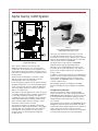
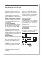
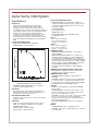
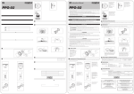
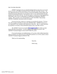
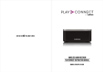
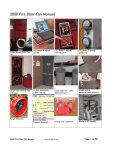
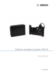
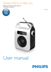
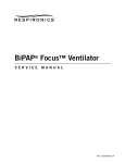
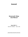
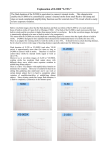
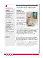
Alpha Sentry CAM System
Features
Patented radon reduction ■
screen
Patented mass flow meter
■
for accurate air flow
measurement
High sensitivity lowers ■
false alarm rate
Optional interface to ■
laboratory-wide computer
for data transfer
Precise radon stripping ■
algorithm
Cleanable, rugged high ■
resolution detector
Patented disposable filter
■
cartridge assembly saves time and labor
Distributed architecture ■
reduces sampling location cost
LCD screen displays ■
spectral data and historical
trends
Continuous self diagnostics
■
ensure system health
Full compliance with ■
ANSI N42.17B
specifications
US Patent 5,128,539
US Patent 5,404,762
US Patent 5,337,603
Description
The Alpha Sentry System
The Alpha Sentry Continuous Air
Monitor (CAM) System resolves
many of the issues facing Alpha
CAM users today. A patented
diffusion screen removes 95% of
the unattached radon daughters
from the air sample (as much as
90% of the radon daughters are
unattached in typical laboratory
environments).
In addition, the spectroscopic
algorithm (which uses a stripping
method instead of ROIs) is
extremely effective at subtracting
out the radon daughter
interference from the transuranic
region of interest.
This physical and mathematical
radon reduction increases the
sensitivity of the Alpha Sentry,
which in turn translates into a lower false alarm rate.
The distributed architecture approach taken by the Alpha Sentry CAM system
enables the user to monitor potential leak situations from a point safely
outside the affected area. Multi-dropping up to eight sampling heads off a
single operator interface (ASM1000), enables the location of the sampling
heads in the room while the ASM1000 resides in the hallway.
Sharing the operator interface resource lowers the cost per sampling
location. It also makes networking to a lab-wide computer easier – there’s
only one connection per eight sampling heads.
In the Alpha Sentry network, the detector and multichannel analyzer
electronics in each sampling head count the activity on the filter and
determine if an acute release has occurred. In addition, the ASM1000 reads
the spectrum from each head at regular time intervals, applies a precise
spectroscopic algorithm, and determines if a chronic release has occurred. In
either case, both the sampling head and the ASM1000 signal an alarm.
The Sampling Head
Based on research conducted by Los Alamos National Laboratory and
Texas A&M University’s Aerosol Laboratory, CANBERRA’s sampling head
represents the most advanced technology available in Alpha CAMs today.
The sampling head contains a patented diffusion screen that removes up to
95% of the newly formed radon daughters particles from the air.
Nuclear Measurement Solutions for Safety, Security and the Environment www.canberra.com
C26929 – 10/05
Alpha Sentry CAM System
Figure 3
In-Line Adapter Allows Direct Connection
of Alpha Sentry Head to Pipe or Duct
Figure 2
Sampling Head Diagram
This is ideal for laboratory environments with
HEPA filtered air which have a low concentration of
condensation nuclei and hence a low attachment rate.
Such facilities typically have high air exchange rates as
well, further increasing the fraction of unattached radon
decay products.
Representative air sampling is ensured by a radial
360° inlet and air channels optimized for uniform
particulate deposition on the filter paper.
In-line monitoring is available with an optional specially
designed manifold. The use of the manifold guarantees
results consistent with the open radial inlet application.
The in-line adapter (Figure 3) connects to any duct or
pipe via 1 in. NPT thread.
The sample is uniformly deposited on a filter encased in
a cartridge. The patented filter cartridges are designed
to save labor and reduce operating costs. When
changing filters, the entire cartridge is easily switched,
rather than handling flimsy filter paper while wearing
gloves. The filter paper within the cartridge is easily
removed for further analysis if needed.
The activity on the filter is counted by a Passivated
Implanted Planar Silicon (PIPS®) detector. This rugged,
cleanable detector is available in two sizes: 450 mm2
and 1700 mm2. The larger detector offers greater
sensitivity due to increased efficiency and greater
possible air flow.
The counts from the detector electronics are stored
in a 256 channel MCA, where they are continuously
monitored for an acute release. Should such an event be
detected, the sampling head annunciates an alarm and
sends its alarm status to the ASM1000.
The alarm device can be either the CANBERRAsupplied optional audio/visual package (driven
internally), or the standard SPDT relay contacts can
be used to drive custom alarm devices. Two LEDs are
present on the head that indicate the counting status –
normal or alarm.
In addition to collecting the spectrum, the sampling head
monitors the flow rate (with a patented mass flow meter),
power supply, and detector voltage. It reports these
values back to the ASM1000, where it is determined if
an alarm condition exists.
The sampling head offer full compliance with ANSI
N42.17B, including the rigorous EMI/RFI susceptibility
tests.
The Alpha Sentry Manager
The operator interface for either a single sampling
head or a network of up to eight sampling heads is the
ASM1000 Alpha Sentry Manager. Its function is two-fold:
to provide graphical and numerical feedback from the
individual heads, and to determine if a chronic release
has occurred.
Using spectroscopic techniques, the ASM1000 strips the
background component due to the 6.0 MeV, 7.68 MeV
and 8.78 MeV radon daughter peaks from the plutonium
region. If the counts in the Pu region are found to
statistically differ from a zero result, the Pu concentration
is calculated, and the DAC-hour value determined.
Alpha Sentry CAM System
This stripping technique is superior to the common ROI
techniques, which use predefined regions and empirical
constants that do not change to reflect changing
conditions.
The analysis can also be set up to detect uranium
instead of plutonium via simple steps in the user interface
of the unit.
The background compensation algorithm is applied to
each spectrum as it is read in from the sampling head.
If the DAC-hour value exceeds the alarm limit, the
ASM1000 will sound an alarm itself, as well as at the
sampling head location where the condition occurred.
The ASM1000 offers an entirely configurable security
system. There are four possible security levels to control
user access. Each menu can be assigned a security
level during system setup. When logging in, only those
menus assigned at the user’s security level will be
accessible. Menus can be assigned multiple levels.
During normal operation, the ASM1000 displays
a graphical status of all the sampling heads attached
to it, showing bar graphs of the flow rate and the
DAC-hour value.
In addition to the DAC-hour alarm, the ASM1000
constantly monitors the flow rate, detector voltage,
filter drawer status (open/closed) and other operational
parameters of the sampling heads and of the network.
If a failure is detected (for example, loss of air flow),
a trouble alarm is annuciated at both the ASM1000 and
individual sampling head locations.
The alarm annunciation is entirely configurable during
system setup. The relay contacts, visual and audible
alarms available at both the sampling head and the
ASM1000, can be configured to annunciate during a
particular condition. For example, during a trouble alarm
the user may choose to illuminate the visual alarm at the
head only, and not annunciate any other alarms.
The ASM1000 contains an LCD display that provides
at-a-glance information for all of the sampling heads
connected to it. A pushbutton keypad completes the
operator interface.
Setup software (Model S578) is available to let a standard
personal computer be used for initial setup, such as
entering alphanumeric IDs for each sampling head.
Software (Model S579) is also available to download
new ASM1000 firmware versions, since the firmware
is resident in reprogrammable non-volatile memory.
The operation of the system through the ASM1000
is entirely menu-driven. Individual head control,
maintenance, configuration and historical trend viewing
are all controlled through easy-to-follow menus.
Both filter changes and performance checks are
automated sequences, with on-screen help to guide
the operator step-by-step. The last filter change date for
each sampling head is tracked automatically by
the ASM1000. User-entered pass/fail criteria tell the
operator whether the unit is still in calibration after
completing a performance check.
Figure 4
Main Screen or Multiple Head Configuration
In the event that the detectable limit is higher than the
alarm limit (due to extreme background conditions), the
ASM1000 replaces the user-entered alarm limit with the
detectable limit and will annunciate an alarm as soon as
the plutonium or uranium is statistically different from the
background.
At any time, the user can look at a detailed display
of an individual spectrum with the touch of a single
button. This screen shows the DAC-hour value, flow
rate, concentration, alarm status, CAM ID, and last
calibration date, in addition to the spectrum. The ability
to view the last alarm spectrum and historical trends is
also provided.
Historical data is stored when the ASM1000 obtains
the spectrum from each sampling head. Counts,
concentration and DAC-hour values are available as
graphical trends. The depth of the history file depends
on the number of sampling heads on the network and
the poll time of the sampling heads. As much as 24 days
of historical data can be stored with a single sampling
head polled every 30 minutes.
Alpha Sentry CAM System
The ASM1000 can be interfaced to a laboratory
computer via the optional RS-485 or RS-232 connection.
This provides uploading of pertinent data (such as
historical trends) for permanent storage and central
monitoring as well as the ability to have the computer
supply the setup configuration.
A single head can be powered directly from the
ASM1000, with no need for external connections.
The head can be located up to 45 m (150 ft) away under
direct power, or up to 1200 m (4000 ft) away via the
RS-485 connection. The latter situation requires local
power to each sampling head.
Multi-dropped CAM Network
Each head in a multiple head configuration requires a
Network Tee Box (NTB) which provides in-line RS-485
and sampling head connections. The NTB contains
individual coding of each sampling head. This type
of connection allows easy installation or removal
of sampling heads on the network. A Network
Terminator (NT) is also required.
The multi-dropped network approach, where up to eight
sampling heads are connected to a single operator
interface (the ASM1000) offers several advantages over
a single head CAM:
Situations can be monitored from a safe location
Potential leaks can be monitored from an ASM1000
located outside the affected area, instead of at the
sampling head location. There is no need to suit up
to enter a potentially contaminated area only to find
it was a false alarm.
Low cost per sampling location
The cost per sampling location is greatly reduced with
up to eight sampling heads sharing the processing
power and operator interface of the ASM1000. This
reduced cost means additional placements are possible
for added protection.
Ease of Networking
With multiple sampling heads already networked to
the ASM1000, there are fewer connections to make
when networking all the CAMs to a laboratory-wide
computer. You need only connect the single ASM1000,
and all the pertinent information from its sampling heads
can be uploaded for further analysis, trending and longterm storage.
External Communications
A standard RS-232 port is provided on the ASM1000 for
output to a printer or setup by a local personal computer
such as a laptop. This connection provides keyboard
support to enter parameters, alarm configuration,
passwords, and alphanumeric CAM identifications into
the Alpha Sentry system.
Operating firmware can easily be updated by
downloading from a personal computer into the flash
resident in the ASM1000.
Host Communications
Host Communications Packages are available options
for the ASM1000. These options include the necessary
hardware, protocol and documentation to communicate
to the ASM1000 via a host computer (Figure 5).
Multiple Alarming Points
Although the sampling heads are connected to a single
ASM1000, the workers are not left unprotected if the
ASM1000 fails. The intelligent sampling heads, each
containing a microprocessor-based MCA, have the
ability to detect an acute release on their own, and to
drive their own alarms. The ASM1000 annunciates
whenever any sampling head on the network is in an
alarm state.
Diagnostics
The ASM1000 contains diagnostics that continuously
check the health of the network and itself. Should a
problem be detected, an alarm will sound to notify users
of any network difficulties.
Network Configuration
There are two different communication scenarios in
the Alpha Sentry system: a single head connected to
an ASM1000, and multiple heads multi-dropped off
an ASM1000.
Figure 5
Example Alpha Sentry Network
Alpha Sentry CAM System
Specifications
SENSITIVITY
Under the following conditions that approximate a
laboratory environment (37 Bq/m3 (1 pCi/L) radon
background, mostly unattached, constant 1 DAC Pu
concentration), the sensitivity is approximately 2 DAC-hours
with 1700 mm2 PIPS, 2.5 DAC-hours with 450 mm2 PIPS.
Under the following conditions that approximate a
non-laboratory environment (37 Bq/m3 (1 pCi/L) radon
background, mostly attached, constant 1 DAC Pu
concentration), the sensitivity is approximately 3.5 DAChours with 1700 mm2 PIPS; 4 DAC-hours with 450 mm2
PIPS.
PARTICLE SIZE DEPOSITION
EQUIVALENT DIAMETER VS. PERCENT
PENETRATION – shown in Figure 6.
Figure 6
Equivalent Diameter vs. Percent Penetration
UNIFORM FILTER DEPOSITION – 9% Coefficient of
Variation for 10 µm AED particles.
EFFICIENCY
Approximately 33% with a 1700 mm2 PIPS detector;
approximately 26% with a 450 mm2 PIPS detector at a
fixed detector to filter spacing of 5 mm.
BACKGROUND REDUCTION
Patented screen removes >95% of newly formed radon
daughter products.
DETECTOR
TYPE – Passivated Implanted Planar Silicon (PIPS).
SIZE – Both 1700 mm2 and 450 mm2 are available.
SYSTEM RESOLUTION –
1700 mm2 PIPS – typically 450 keV;
450 mm2 PIPS – typically 325 keV.
FILTER CARTRIDGE AND FILTER
PRESSURE DROP – 12.44 kPa (50 in. H2O) across
sampling head with AS047 filter paper, at 0.94 x 10⁻³ m3/s
(2 cfm) using 1700 cartridge or 0.47 x 10⁻³ m3/s (1 cfm)
using 450 cartridge.
Filter (Model AS047).
TYPE – Millipore® SS.
PORE SIZE – 3 µm.
ACTIVE DIAMETER – with 1700 PIPS: 42 mm;
with 450 PIPS: 24 mm.
450 mm2
OD – 4.765 cm (1.876 in.)
ID – 2.390 cm (0.941 in.)
Height – 1.91 cm (0.75 in.)
1700 mm2
OD – 4.765 cm (1.876 in.)
ID – 4.191 cm (1.650 in.)
Height – 1.91 cm (0.75 in.)
COMMUNICATIONS
NUMBER OF SAMPLING HEADS – Up to eight on a
single ASM1000.
SINGLE HEAD CABLE LENGTH – 3 m (10 ft) cable
standard; maximum distance for single sampling head
powered directly from ASM1000 is 45 m (150 ft) using
22 gauge wire for the power cable; maximum distance for
single sampling head powered locally is 1200 m (4000 ft).
The latter requires a Model CA2001 Network Terminator.
MULTI-DROPPED HEAD CABLE LENGTH –
Total network distance (RS-485) is 1200 m (4000 ft),
maximum.
COMMUNICATIONS WITH EXTERNAL COMPUTERS
Model ASM01 or ASM02 Communications Package
(hardware, protocol and documentation).
COMMUNICATIONS PORTS
SAMPLING HEAD – RS-485 for communication to
ASM1000.
ASM1000 – RS-232 for PC setup or printer and RS-485
for communication to sampling head standard; second
port optional via Host Computer Interface, Model ASM01
RS-485 Multi-Drop or Model ASM02 RS-232.
PHYSICAL
WEIGHT – Sampling Head: 3.6 kg (8.0 lb); ASM1000:
4.2 kg (9.3 lb).
SAMPLING HEAD – Diameter of head: 17.8 cm (7 in.);
diameter including vacuum connection and door knob:
22.9 cm (9 in.); height: 30.5 cm (12 in.).
ASM1000 – 31.8 cm (12.5 in.) high; 21.6 cm (8.5 in.) wide;
8.9 cm (3.5 in.) deep, with no mounting hardware.
10.36 cm (4.08 in.) deep with feet or 9.60 cm (3.78 in.)
deep with mounting bracket.
VACUUM CONNECTION – Male; for 9.5 mm (3/8 in.)
ID hose.
POWER
SAMPLING HEAD – 24 V ac, 50/60 Hz, <15 W.
ASM1000 – 100–130 V ac, 60 Hz, 40 W. Fuse – 250 V ac
1/2 A Slow Blow.
Alpha Sentry CAM System
ENVIRONMENTAL
OPERATING TEMPERATURE: Sampling Head – 0 to
50 °C; ASM-1000 – 0 to 50 °C.
OPERATING HUMIDITY: Sampling Head – 0-95%
relative, non-condensing; ASM-1000 – 0-95% relative,
non-condensing.
ALARMS
Status –
■ Filter Door Open
Communication Network Down
■
■
■
■
■
■
Low Flow Rate
High Flow Rate
Detector Voltage
Power
Exposure
– Acute
–Chronic
■ Concentration
ASM1000 – Standard.
AUDIBLE – Selectable 90 or 70 dB (2900 Hz) at 60 cm
(2 ft).
VISUAL – Amber (trouble) and Red (exposure), 32.3 x 103
lux (3000 end footcandles), average.
Relay contacts are standard (SPDT) – 0.3 A at 30 V ac
Trouble and Exposure.
Sampling Head – Optional.
Model AS020 CAM Sampling Head Alarm, one per head:
AUDIBLE – Selectable 90 or 84 dB (2900 Hz) at 60 cm (2 ft).
VISUAL – >3 watt-second xenon flash tube.
Relay contacts are standard (SPDT) – 0.3 A at 30 V ac, Trouble and Exposure.
FLOW MEASUREMENT
RANGE – 0.24 x 10⁻³ to 1.42 x 10⁻³ m3/s (0.5 to 3.0 cfm).
RECOMMENDED FLOW SETTING –
0.47 x 10⁻³ m3/s (1 cfm) for 450 mm2 detector.
0.94 x 10⁻³ m3/s (2 cfm) for 1700 mm2 detector.
Meter
TYPE – Hot wire anemometer. Accuracy – ±5%.
ANSI 42.17B COMPLIANCE
ASM1000, AS450R and AS1700R are fully compliant.
UL 61010-1:2004 and CAN/CSA C22.2 No. 61010-1-04
COMPLIANCE
ASM1000, AS450R and AS1700R are fully compliant.
Table 1
RFI/EMI Susceptibility of
Sampling Heads
Test Condition AS1700R
(Standard)
Electric Fields
ANSI N42.17B, Step 7.1.2.2:
30 to 35 MHz sweep
Vertical >100 V/m
Horizontal
>100 V/m
RF Field
ANSI N42.17B, Step 7.1.2.3:
140 MHz
Vertical >100 V/m
Horizontal
>100 V/mv
Microwave Field
ANSI N42.17B, Step 7.2:
915 MHz
Vertical >200 V/m
Horizontal
>200 V/m
Microwave Field
ANSI N42.17B, Step 7.2:
2450 MHz
Vertical >200 V/m
Horizontal
>200 V/m
Electrostatic Fields
ANSI N42.17B, Step 7.3:
5000 V
No Effect
Alpha Sentry CAM System
ASM1000 DISPLAY
SIZE – 16.25 cm (6.4 in.) (diagonal).
TYPE – TFT – LCD with backlight.
RESOLUTION – 640 x 480 VGA.
CONTROL PANEL – 24 pushbuttons.
INFORMATION DISPLAYED –
■ DAC-hour Value.
Flow Rate.
■
■
■
■
■
■
■
■
Concentration (in user-specified units).
Alarm Set Point.
Alarm Status.
Sampling Head ID and Serial Number.
Last Calibration Date for the Sampling Head.
MCA Spectrum.
Time and Date (accurate to 1 minute per month).
■ Total volume through filter.
HISTORICAL DATA STORAGE
(for 30 minute poll time)
One Sampling Head: 24 days
Two Sampling Heads: 12 days
Four Sampling Heads: 6 days
Eight Sampling Heads: 3 days
ASM1000 MENU FUNCTIONS
FILTER CHANGE – Provides automated Filter Change
sequence and Time/Date stamp.
PERFORMANCE CHECK – Provides automated
Performance Check sequence and Pass/Fail indication.
DATA REVIEW – Historical Trends, Alarm Log and
Spectral Data.
SYSTEM SETUP – Parameters, Check Source, Individual
Head Control, Network Configuration and Calibration.
LOG IN/LOG OUT – Allows access to various options
according to password level.
SAMPLING HEADS
AS450R – Radial Inlet with 450 mm2 PIPS.
AS1700R – Radial Inlet with 1700 mm2 PIPS.
ALPHA SENTRY MANAGER
ASM1000 – Alpha Sentry Manager.
PIPS is a registered trademark of CANBERRA Industries, Inc.
Millipore is a registered trademark of Millipore Corporation.
© 2005 CANBERRA Industries, Inc. All rights reserved.
OPTIONS
Model AS020 Alarm Option for Sampling Head.
Model AS010 In-Line Manifold Option for Sampling Head.
Model AS031 Filter Cartridges for 450 mm2 Sampling
Heads, Package of 25.
Model AS032 Filter Cartridges for 1700 mm2 Sampling
Heads, Package of 25.
Model C2000-X Communications Cable (ASM1000 to
Multiple Sampling Heads).
Model C2001-X Communications/Power Cable (ASM1000
to single Sampling Head; consists of C2000-X
and C2003-X).
Model C2002-X Network Access Cable (NTB to head).
Model C2003-X Power Cable (ASM1000 to Single
Sampling Head).
Model C2004 ASM1000/PC Setup Cable; 1.8 m (6 ft)
25-pin to 9-pin.
Model CA2000 Network Tee Box (NTB), includes 3 m
(10 ft) C2002 and CA2001.
Model CA2001 Network Terminator (NT).
Model AS047 Filter Paper, 47 mm; package of 100.
Model AS050 Wall Mounting Bracket for Sampling Head.
Model AS060 Replacement Screen for Sampling Head
package of 2.
Model AS070 Power Supply for Sampling Head
(115 V ac line).
Model AS080 241Am Calibration Check Source for
AS450R Sampling Heads.
Model AS085 241Am Calibration Check Source for
AS1700R Sampling Heads.
Model ASM01 RS-485 Host Computer Interface.
Model ASM02 RS-232 Host Computer Interface.
Model S578 Alpha Sentry PC Setup Software and
cable C2004.
Model S579 Alpha Sentry Configuration and Firmware
Update Software and cable C2004.
ACCESSORIES
Five filter cartridges supplied with each sampling head.
One C2001-10 Cable Set and wall mounting kit supplied
with each ASM1000.
Model AS-MAN Alpha Sentry CAM System User’s Manual;
supplied when requested.