1
8VHU¶VPDQXDO
(QJLQHHU,71DYLJDWRU
&$3
7KLVPDQXDOEHORQJVWR
8VHU¶VPDQXDO
(QJLQHHU,71DYLJDWRU
&$3
$ERXWWKLVPDQXDO
DocID: 1MRK 511 142-UEN
Issue date: June 2004
Revision: A
Data subject to change without notice
© Copyright 2004 ABB. All rights reserved.
&23<5,*+7
We reserve all rights to this document, even in the event that a patent is issued and a different commercial proprietary right is registered. Improper use, in particular reproduction and dissemination to
third parties, is not permitted.
This document has been carefully checked. However, in case any errors are detected, the reader is
kindly requested to notify the manufacturer at the address below.
The data contained in this manual is intended solely for the concept or product description and is not
to be deemed to be a statement of guaranteed properties. In the interests of our customers, we constantly seek to ensure that our products are developed to the latest technological standards.
As a result, it is possible that there may be some differences between the HW/SW product and this
information product.
IndustrialIT
Industrial IT enabled products from ABB are the building blocks for greater productivity, featuring all
the tools necessary for lifecycle product support in consistent electronic form.
0DQXIDFWXUHU
ABB Automation Technologies AB
Substation Automation
SE-721 59 Västerås
Sweden
Telephone: +46 (0) 21 34 20 00
Facsimile: +46 (0) 21 14 69 18
www.abb.com/substationautomation
Contents
Chapter
Page
Introduction ............................................................................................................. 5
Intended use of this manual ................................................................................. 5
Intended audience................................................................................................ 5
Responsibilities ............................................................................................... 5
What is in this manual? ........................................................................................ 5
How to find more information ............................................................................... 6
Application............................................................................................................... 7
CAP 540 Terminal tool box .................................................................................. 7
Requirements .......................................................................................................... 9
Supported terminal versions ................................................................................ 9
Installation ............................................................................................................. 11
Installation of CAP 540 Navigator ...................................................................... 11
Installation of Remote Connection option .......................................................... 14
Uninstallation of CAP 540 Navigator.................................................................. 15
How To Use CAP 540 ............................................................................................ 17
Navigate in CAP 540.......................................................................................... 17
How to Log on............................................................................................... 18
How to build a new project tree..................................................................... 20
How to edit the project tree ........................................................................... 22
Properties...................................................................................................... 24
Parameter setting............................................................................................... 25
Disturbance Handling......................................................................................... 26
Station level .................................................................................................. 26
Terminal level................................................................................................ 27
Disturbance Records List .............................................................................. 28
Disturbance Evaluation ...................................................................................... 33
1MRK 511 142-UEN*1p3rA
Configuration of terminals with CAP 531 ...........................................................34
How to start CAP 531 from terminal level in CAP 540 ..................................35
Import a SMS project tree ............................................................................. 35
Import of an old CAP 531 configuration ........................................................36
Other programs ..................................................................................................38
Time Scheduler .............................................................................................38
Time Synchronization.................................................................................... 41
LED Indications .............................................................................................42
Event List ......................................................................................................43
Tools ..................................................................................................................44
Terminal Emulator.........................................................................................44
File Conversion .............................................................................................45
FTP Client .....................................................................................................45
User defined menus ......................................................................................47
Settings .............................................................................................................. 48
General settings ............................................................................................48
Communication settings................................................................................49
HTML settings ...............................................................................................55
Compress/Decompress......................................................................................55
Exit CAP 540 ......................................................................................................56
Appendix A, Toolbar buttons and menus ...........................................................57
Toolbar buttons ..................................................................................................57
Menus ................................................................................................................58
File ................................................................................................................58
Edit ................................................................................................................58
Settings .........................................................................................................59
Programs....................................................................................................... 59
View .............................................................................................................. 60
System ..........................................................................................................60
Tools .............................................................................................................60
Help...............................................................................................................61
4
1MRK 511 142-UEN*1p3rA
,QWHQGHGXVHRIWKLVPDQXDO
Introduction
,QWURGXFWLRQ
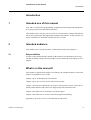
,QWHQGHGXVHRIWKLVPDQXDO
CAP 540 is a collection of programming, configuration and setting tools and libraries
for a range of protection and control terminals.
This manual can be used to get an overview of CAP 540 and its contents and information on PC requirements and supported terminal product families. It also provides necessary information to install the terminal tool box CAP 540.
,QWHQGHGDXGLHQFH
This manual can be used by operators, commissioners and system engineers.
5HVSRQVLELOLWLHV
In order to fully understand the contents of this manual, you should have basic engineering knowledge and specific knowledge in system automation, depending on your
purpose.
:KDWLVLQWKLVPDQXDO"
This manual is organized into chapters according to the intended audience so that each
chapter corresponds to user’s needs.
Chapter 1 gives an introduction to the manual.
Chapter 2 gives an overview of CAP 540 and its contents.
Chapter 3 specifies the requirements for your PC and operative system. It also shows
which product families and releases are supported by this terminal tool box.
Chapter 4 describes how to install the CAP 540 Navigator.
Chapter 5 describes how to use the CAP 540 Navigator functionality.
Appendix A gives an overview of Toolbar buttons and menus.
1MRK 511 142-UEN*1p3rA
5
+RZWRILQGPRUHLQIRUPDWLRQ
Introduction
+RZWRILQGPRUHLQIRUPDWLRQ
The following manuals provide complementary information:
• CAP 531*1.6 Configuration and Programming tool, User’s Manual,
1MRK 511 105-UEN
• PST*1.2 Parameter Setting tool, User’s Manual, 1MRK 511 114-UEN
• REVAL*2.0, User´s Manual, 1MRK 511 053-UEN
6
1MRK 511 142-UEN*1p3rA
&$37HUPLQDOWRROER[
Application
$SSOLFDWLRQ
&$37HUPLQDOWRROER[
CAP
CAP540
540
Navigator
Navigator
Parameter
ParameterSetting
Setting
Disturbance
DisturbanceHandling
Handling
Disturbance
DisturbanceEvaluation
Evaluation
Configuration
Configuration
Option
Option
Remote
RemoteConnection
Connection
Option
Option
Settings
SettingsVisualisation
VisualisationTool
Tool Option
Option
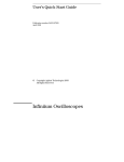
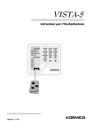
The CAP 540 terminal tool box contains these programming, configuration and setting tools
and libraries for a range of protection and control terminals:
• CAP 540, Navigator
• PST, Parameter Setting Tool
• Disturbance Handling
• REVAL, Disturbance Evaluation
• CAP 531, Configuration and Programming Tool
• Remote Connection
• SVT, Setting Visualization Tool
CAP 540 also contains the User’s Manuals for the tools in pdf-format and Acrobat Reader to
view the manuals.
Internet Explorer 4 is also provided. It is needed for the help system in PST.
1MRK 511 142-UEN*1p3rA
7
&$37HUPLQDOWRROER[
Application
When you install CAP 540 Navigator, you get the following documents:
7DEOH'RFXPHQWV&$3
'RFXPHQW
1XPEHU
CAP 540*1.3 (This document)
1MRK 511 142-UEN
Navigator
User’s Manual
CAP 531*1.6
1MRK 511 105-UEN
Configuration and Programming tool
User’s Manual
PST*1.2
1MRK 511 114-UEN
Parameter Setting tool
User’s Manual
SVT*1.0
1MRK 511 122-UEN
Setting Visualisation Tool
User´s Manual
REVAL*2.0
1MRK 511 053-UEN
Disturbance Evaluation
User´s Manual
Installation and Commissioning manual
8
1MRK 511 123-UEN
1MRK 511 142-UEN*1p3rA
6XSSRUWHGWHUPLQDOYHUVLRQV
Requirements
5HTXLUHPHQWV
7DEOH5HTXLUHPHQWVRQ3&
,WHP
0LQLPXPUHTXLUHG
Processor / Frequency
Pentium / 233MHz
RAM
128 MByte
Disk space
500 MByte
Monitor / Resolution
VGA compatible / 1024 x 768
CD-ROM drive
Needed to install the terminal tool box
7DEOH5HTXLUHPHQWVRQRSHUDWLYHV\VWHPDQGKHOSYLHZHU
2SHUDWLYH6\VWHP
$''21V
+HOSYLHZHU
Windows 95
DCOM 95
Internet Explorer 4 or later
Windows 98
DCOM 98 second edition Internet Explorer 4 or later
Windows NT 4.0
Service Pack 4 or higher
Internet Explorer 4 or later
Windows 2000
–
Internet Explorer 4 or later
Windows XP Professional Service Pack 1
Internet Explorer 4 or later
6XSSRUWHGWHUPLQDOYHUVLRQV
REL 012*1.0
REL 5xx*1.0 and later
REL 100*3.0
REO 5xx*2.1 and later
REG 1xx*3.0
RES 505*2.3 and later
REOR 100*2.2 and *3.0
RET 521*2.0 and later
REB 551*1.1 and later
RED 521*2.0
REC 561*1.0 and later
1MRK 511 142-UEN*1p3rA
9
6XSSRUWHGWHUPLQDOYHUVLRQV
Requirements
10
1MRK 511 142-UEN*1p3rA
,QVWDOODWLRQRI&$31DYLJDWRU
Installation
,QVWDOODWLRQ
This chapter describes how to install the different parts in the CAP 540 Navigator.
1RWH
:KHQLQVWDOOLQJLQ:LQGRZV17:LQGRZVDQG:LQGRZV;3\RXQHHGWRORJRQDV
DGPLQLVWUDWRU
,QVWDOODWLRQRI&$31DYLJDWRU
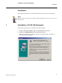
This section describes how to install the CAP 540 Navigator.
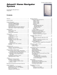
1 Insert the CAP 540 installation CD in the CD-ROM drive of your PC.
2 Double-click &$3VHWXSH[H using Windows Explorer.
Enter your name in the first dialog. This name will appear under “Licensed to:”.
The following dialog appears.
1MRK 511 142-UEN*1p3rA
11
,QVWDOODWLRQRI&$31DYLJDWRU
Installation
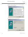
3 Read the message and click 1H[W if you want to continue with the installation.
The License Agreement dialog appears.
4 Click 1H[W and the Destination Location dialog appears.
12
1MRK 511 142-UEN*1p3rA
,QVWDOODWLRQRI&$31DYLJDWRU
Installation
5 Select the drive and the folder where the CAP 540 software shall be installed and
then click1H[W.
The Start Installation dialog appears.
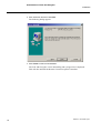
6 Click 1H[W to continue
The CAP 540 software Navigator is now being installed in your computer, showing
you an installation progress bar. Then the following dialog appears.
1MRK 511 142-UEN*1p3rA
13
,QVWDOODWLRQRI5HPRWH&RQQHFWLRQRSWLRQ
Installation
7 Click the )LQLVK button, and the installation is completed.
8 Next step is to install other Terminal Tool Box applications.
Follow the instructions on the screen until the installation is finished.
You may then have to restart the computer.
Acrobat Reader and Internet Explorer.
The CD-ROM also contains Acrobat Reader and Internet Explorer
You have to continue with installing Acrobat Reader if you don’t have this program
installed already on your computer.
The help function in the Parameter Setting Tool uses Internet Explorer.
If you do not have Internet Explorer on your computer, you need to install it.
,QVWDOODWLRQRI5HPRWH&RQQHFWLRQRSWLRQ
This chapter describes how to install the Remote Connection option. The Remote Connection option is only supplied on the CD if ordered.
1 Insert the CAP 540 installation CD in the CD-ROM drive of your PC.
2 Double-click 5HP&RQ6HWXSH[H using Windows Explorer.
3 Click 2. button to start installation.
14
1MRK 511 142-UEN*1p3rA
8QLQVWDOODWLRQRI&$31DYLJDWRU
Installation
8QLQVWDOODWLRQRI&$31DYLJDWRU
This chapter describes how to uninstall the CAP 540 Navigator.
1 Go to the 6WDUWmenu, select 3URJUDPV, then &$3
2 Click 8QLQVWDOO
The uninstall of CAP 540 starts and the following dialog appears.
1MRK 511 142-UEN*1p3rA
15
8QLQVWDOODWLRQRI&$31DYLJDWRU
Installation
3 Click Automatic and then click 1H[W
The following dialog appears.
4 Click )LQLVKto start the uninstallation.
The CAP 540 Navigator is now uninstalling and a progress bar is displayed.
This will also uninstall the Remote Connection option if installed.
16
1MRK 511 142-UEN*1p3rA
1DYLJDWHLQ&$3
How To Use CAP 540
+RZ7R8VH&$3
This section describes how to navigate in CAP 540 and perform Configuration,
Parameter setting, Disturbance Handling and Disturbance Evaluation.
1DYLJDWHLQ&$3
CAP
CAP540
540
Navigator
Navigator
Parameter
ParameterSetting
Setting
Disturbance
DisturbanceHandling
Handling
Disturbance
DisturbanceEvaluation
Evaluation
Configuration
Configuration
Option
Option
Remote
RemoteConnection
Connection
Option
Option
Settings
SettingsVisualisation
VisualisationTool
Tool Option
Option
CAP 540 is used through all stages of normal operation from parameter setting, commissioning and power system disturbance evaluation. It can also be used to clear front
indications, switch setting groups and turn autoreclosure on/off. The engineering work
can be done off-line on the PC. The configuration is prepared and tested before the
commissioning. The system for disturbance handling is prepared and tested during
commissioning.
1MRK 511 142-UEN*1p3rA
17
1DYLJDWHLQ&$3
How To Use CAP 540
+RZWR/RJRQ
In order to use CAP 540 it must be installed in your computer, see How to install CAP
540. When starting CAP 540 the following Log On dialog appears:
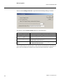
Fill in User Name and Password and click 2.. This dialog contains the possibility to
change the password. Note that the password may have been linked by the Administrator to a certain authority level.
To change password click on button “Change Password”. The following dialog
appears:
Type in User Name, Old Password, New Password and Confirm new Password.
1RWH
,I\RXORJRQIRUWKHILUVWWLPH\RXPXVWDOVRHQWHUWKH³&KDQJH3DVVZRUG´GLDORJWR
FUHDWHDQHZSDVVZRUGEXWGRQRWW\SHDQ\WKLQJLQWKHROGSDVVZRUGWH[WER[
18
1MRK 511 142-UEN*1p3rA
1DYLJDWHLQ&$3
How To Use CAP 540
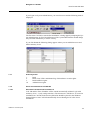
If you logon as a System Administrator, you can select users and the following menu is
displayed:
The first time CAP 540 is started after installation, a dialog appears prompting the System Administrator for User Id and Password. The system administrator should change
this password immediately to ensure security.
If you click 8VHUVthe following dialog appears where you can add/delete users and
define authority levels.
$XWKRULW\OHYHOV
1.
2.
3.
10.
Read
Read, Clear LED’s and Manual trig of disturbance recorder rights.
Read and Write rights.
Administrator rights.
2WKHUVWDUWDOWHUQDWLYHVRI&$3
6WDUWZLWK&RPPDQG/LQH3DUDPHWHU$
CAP 540 and the Time Scheduler will be started automatically without Login with
Authority level = 1 (only read permission). The shortcut of CAP540.exe /A created at
installation in CAP 540 main directory\ShortCut should be placed in the Windows
Startup folder to start CAP 540 automatically when rebooting the PC after Power
breakdown.
1MRK 511 142-UEN*1p3rA
19
1DYLJDWHLQ&$3
How To Use CAP 540
6WDUWZLWK&RPPDQG/LQH3DUDPHWHU%8VHU,G3DVVZRUG
CAP 540 will be started automatically without Login with UserId and Password as
Command Line Parameters. If the UserId or Password is not valid CAP 540 will yet be
started but Authority level will be set to 1 (only read permission).
Create a shortcut of the program file CAP540.EXE on the desktop and type in the target text box of the shortcut e.g. C:\CAP540\CAP540.EXE /B,UserId,Password.
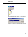
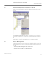
+RZWREXLOGDQHZSURMHFWWUHH
When you have logged on as a first time CAP 540 user the following screen appears.
The Demo project kan not be altered for this reason.
Project can be stored on a local or network drive.
Create a new project by selecting )LOH1HZ3URMHFW. Select Prj1.nbp and type the file
name in the New Project dialog box e.g. a Power Network name like SouthNet. Click
OK. A project structure down to Bay level will be created with default names. Right
click on the nodes and select Add to add more nodes to your project.
20
1MRK 511 142-UEN*1p3rA
1DYLJDWHLQ&$3
How To Use CAP 540
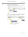
When you have filled in all names your tree may look like below:
The last level is the Terminal level. Right click on a bay and select Add. In the Terminal Modules dialog select a terminal e.g. REL 521*2.3.
Type in a vacant slave number (it must be unique for each terminal that belongs to the
same SPA loop).
1MRK 511 142-UEN*1p3rA
21
1DYLJDWHLQ&$3
How To Use CAP 540
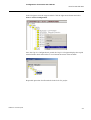
Now the structure may look like this (Example of a complete structure down to Terminal level).
+RZWRHGLWWKHSURMHFWWUHH
5HPRYH
Right click on a node (all nodes except Project) or click on menu Edit and select
Remove. The selected node will now be deleted with all its configuration, setting and
disturbance data.
5HQDPH
Right click on a node (all nodes except Terminal) or click on menu Edit and select
Rename or click on the node name once. Type the new name in the appeared text box.
1RWH
,IWKHSURMHFWLVFUHDWHGLQDSUHYLRXVYHUVLRQRI&$3ORQJILOHQDPHV
!FKDUDFWHUVUHODWHGWRHDFKQRGHQDPHLQWKHSURMHFWVWUXFWXUHDUHQRWVXSSRUWHG
:KHQDQRGHLVUHQDPHGRQO\WKHILUVWFKDUDFWHUVZLOOEHXVHGLQWKHILOHQDPHDQG
WKHVHFKDUDFWHUVPXVWDOVREHXQLTXHIRUWKHQRGHQDPH
22
1MRK 511 142-UEN*1p3rA
1DYLJDWHLQ&$3
How To Use CAP 540
5HDVVLJQ
Right click on a Terminal node or click on menu Edit and select Reassign. In the Terminal Modules dialog select a new Terminal of same type and version as the old one.
&XW
Right click on a node (all nodes except Project and Organization) or click on menu
Edit and select Cut. Click on a node RQHOHYHODERYH the selected node and click on
Paste. The first selected node will now be moved to a location below the second
selected node with a new default name.
1RWH
7KHPHQXLWHP3DVWHZLOORQO\EHYLVLEOHIRUYDOLGQRGHW\SHV
&RS\3DVWH
Right click on a node (all nodes except Project and Organization) or click on menu
Edit and select Copy. Click on a node RQHOHYHODERYH the selected node and click on
Paste. A copy of the first selected node will now be created below the second selected
node with a new default name.
1RWH
7KHPHQXLWHP3DVWHZLOORQO\EHYLVLEOHIRUYDOLGQRGHW\SHV
0RYHLQVHUW
This function is used to reorganize nodes below the same parent node.
Right click on a node (all nodes except Project) or click on menu Edit and select Move.
Click on another node on WKHVDPHOHYHO as the first selected one and click on Insert.
The first selected node will now be moved to a location below the second selected
node.
1RWH
7KHPHQXLWHP,QVHUWZLOORQO\EHYLVLEOHIRUQRGHVEHORZWKHVDPHSDUHQWQRGHDVWKH
ILUVWVHOHFWHGQRGH
1MRK 511 142-UEN*1p3rA
23
1DYLJDWHLQ&$3
How To Use CAP 540
3URSHUWLHV
Right click on a Terminal node or click on menu Edit and select Properties to open the
Terminal Properties dialog, see table below.
24
Terminal Name
Terminal name with version number.
Module Name
Terminal module name.
Node Name
Terminal node name in project tree.
Additional Text
User defined additional text to Terminal node name.
Slave Number
Unique Terminal identification number.
Display Template
Template for viewing disturbances. The template is created in
the Disturbance Evaluation Program REVAL.
Print Template
Template for printing disturbances. The template is created in
the Disturbance Evaluation Program REVAL.
1MRK 511 142-UEN*1p3rA
3DUDPHWHUVHWWLQJ
How To Use CAP 540
3DUDPHWHUVHWWLQJ
CAP
CAP540
540
Navigator
Navigator
Parameter
ParameterSetting
Setting
Disturbance
DisturbanceHandling
Handling
Disturbance
DisturbanceEvaluation
Evaluation
Configuration
Configuration
Option
Option
Remote
RemoteConnection
Connection
Option
Option
Settings
SettingsVisualisation
VisualisationTool
Tool Option
Option
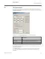
Start Parameter Setting from a terminal node with a right mouse click, see below or
with a left mouse click on menu Programs.
1MRK 511 142-UEN*1p3rA
25
'LVWXUEDQFH+DQGOLQJ
How To Use CAP 540
Click 3DUDPHWHU6HWWLQJ with left mouse button and the Parameter Setting screen
appears. It is also possible to start Parameter Setting by clicking on the Parameter Setting tool bar button.
Continue according to the manual for PST (Parameter Setting).
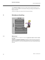
'LVWXUEDQFH+DQGOLQJ
CAP
CAP540
540
Navigator
Navigator
Parameter
ParameterSetting
Setting
Disturbance
DisturbanceHandling
Handling
Disturbance
DisturbanceEvaluation
Evaluation
Configuration
Configuration
Option
Option
Remote
RemoteConnection
Connection
Option
Option
Settings
SettingsVisualisation
VisualisationTool
Tool Option
Option
6WDWLRQOHYHO
Position the cursor on a Station level and click ULJKWPRXVHEXWWRQRUFOLFNRQPHQX
3URJUDPV
Continue with 'LVWXUEDQFH+DQGOLQJ and with any of the active choices in next dialog (Station Disturbance Upload or Station Disturbance File Transfer depending on if
there is a Station PC or not). All new disturbances/files for the selected station will be
uploaded.
26
1MRK 511 142-UEN*1p3rA
'LVWXUEDQFH+DQGOLQJ
How To Use CAP 540
To make communication settings on the station level, see “Communication settings”
on page 49.
7HUPLQDOOHYHO
Position the cursor on Terminal level and click the right mouse button. Continue with
Disturbance Handling and with any of the active choices in next dialog (terminal disturbance list or terminal disturbance file list depending on if there is a station pc or
not). It is also possible to trig the disturbance recorder manually, clear LED’s or clear
all recordings.
1MRK 511 142-UEN*1p3rA
27
'LVWXUEDQFH+DQGOLQJ
How To Use CAP 540
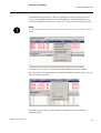
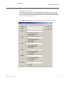
'LVWXUEDQFH5HFRUGV/LVW
Disturbance Records List shows the resulting data in four different displays: the list of
disturbances (or list of disturbance files if you work from a Central PC towards Station
PC) and three other displays of disturbance information data.
28
1MRK 511 142-UEN*1p3rA
'LVWXUEDQFH+DQGOLQJ
How To Use CAP 540
7DEOH'LVWXUEDQFH5HFRUGV/LVW
'DWH
7LPH
6HT1R
Recording Recording Recording
Date
Time
Sequence
Number
6WRUHGLQ
6WDWLRQ3&
6WRUHGLQ
7HUPLQDO
7ULJ6LJQDO
Disturbance
files (see below)
stored locally on
disk (Central PC
or Station PC)
Disturbance
Recording start
files (see below) condition
stored remotely
on disk or terminal (Station PC
or Terminal)
)DXOW
/RFDWLRQ
)DXOW
7\SH
)DXOW
'LUHFWLRQ
Fault Location
in% and km/
miles
Fault type: Fault Direction:
L1-N
Forward
L2-N
Forward beyond
range
L3-N
L1-L2
L2-L3
L3-L1
R = Disturbance file REVAL format (.REV)
T = Disturbance file COMTRADE format (.DAT)
H = Header file REVAL format (.REH)
G = Header file COMTRADE format (.CFG)
D = Disturbance report file (.RSD)
E = Disturbance file EVE format
1MRK 511 142-UEN*1p3rA
29
'LVWXUEDQFH+DQGOLQJ
How To Use CAP 540
'LVWXUEDQFH5HFRUGV/LVWFRQWLQXH
/LQH
/LQH
/HQJWK )UHTXHQF\
Line
Length in
km/miles
6DPSOLQJ 3UHIDXOW
5DWH
7LPH
Line Frequency Sampling
in Hz
Rate in Hz
3RVWIDXOW 3RVWIDXOW 7RWDO
7LPH
7LPH
5HFRUGLQJ
7LPH
Prefault Time Postfault
in ms
Time in ms
(REOR 100)
Postfault
Time in ms
(REOR 100)
5HFRUGLQJ
7LPH/LPLW
&7(DUWK
Total Recording Recording Time CT-Earth: in
Time in ms
Limit in ms
or out
7DEOH$QDORJ&KDQQHOV
1DPH
Channel Channel
number Name:
user
defined
6FDOH
)DFWRU
7ULJ
/RZ
2Q
TransLower trig
former
value in%
Ratio in kV
or A
7ULJ
+LJK
Lower
Higher trig
trigger
value in%
activated
status: Yes
or No
2Q
7ULJ
7ULJ
9DOXH
506
506
3UHIDXOW )DXOW
$FWLYH
Higher
Trigger
activated
status: Yes
or No
Trigger
status:
High or
Low
Channel
value at
trigger
time in kV
or A
RMS Pre- RMS Fault Channel
fault value: value:
enabled:
Yes or
Value/
Value/
No
angle
angle
kV/A/Deg. kV/A/Deg.
7DEOH'LJLWDO&KDQQHOV
Channel number
1DPH
6HWWLQJ
7ULJ2Q
7ULJ9DOXH
$FWLYH
Channel Name:
Normal channel
status:
Trigger enabled:
Value at trigger time:
Yes or No
Open or Closed
Trigger status at trigger time:
user defined
Open = NO
Yes or No
Closed = NC
7DEOH(YHQWV
Event number
1DPH
7LPH
6WDWXV
Event name:
Event time:
Event status:
User defined
hh: mm: ss: ms ms
On or Off
The disturbance records have different colours based on different conditions.
Red
Disturbances/files that have not been uploaded.
Blue
The disturbance was recently uploaded and stays blue until you update the terminal disturbance list. This disturbance then turns black.
Black
The disturbance is “old”
30
1MRK 511 142-UEN*1p3rA
'LVWXUEDQFH+DQGOLQJ
How To Use CAP 540
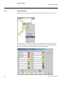
The Disturbance Records List is the list of disturbances and will indicate with UHG
color new not uploaded disturbances and with EOXH new uploaded disturbances. By
clicking the right mouse button on a red row you will get the following pop-up menu:
1RWH
<RXDOVRJHWLQIRUPDWLRQRIIDXOWORFDWLRQDQGIDXOWW\SHLIWKH\DUHDYDLODEOHLQWKHWHU
PLQDO
From this menu you can e.g. upload the selected disturbance from the terminal.
By clicking the right mouse button on an uploaded disturbance (black or blue) you get
the following pop-up menu:
From this menu you can e.g. start Disturbance Evaluation (REVAL) and print
disturbance data.
1MRK 511 142-UEN*1p3rA
31
'LVWXUEDQFH+DQGOLQJ
How To Use CAP 540
Click the left mouse button on an uploaded disturbance to get additional information in
the lower three displays analog channels, digital channels and events, see below.
32
1MRK 511 142-UEN*1p3rA
'LVWXUEDQFH(YDOXDWLRQ
How To Use CAP 540
'LVWXUEDQFH(YDOXDWLRQ
CAP
CAP540
540
Navigator
Navigator
Parameter
ParameterSetting
Setting
Disturbance
DisturbanceHandling
Handling
Disturbance
DisturbanceEvaluation
Evaluation
Configuration
Configuration
Option
Option
Remote
RemoteConnection
Connection
Option
Option
Settings
SettingsVisualisation
VisualisationTool
Tool Option
Option
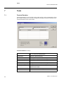
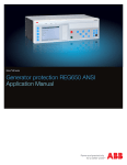
Disturbance Evaluation with the program REVAL can be started by double clicking
the disturbance in the Disturbance Records List, clicking the icon for REVAL in the
toolbar and browse the available files or from the dialog when right clicking an
uploaded disturbance. The chart will appear as below. You can there study the analogue curves and the digital signals.
Refer to the REVAL manual for further guidance.
1MRK 511 142-UEN*1p3rA
33
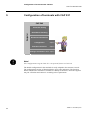
&RQILJXUDWLRQRIWHUPLQDOVZLWK&$3
How To Use CAP 540
&RQILJXUDWLRQRIWHUPLQDOVZLWK&$3
CAP
CAP540
540
Navigator
Navigator
Parameter
ParameterSetting
Setting
Disturbance
DisturbanceHandling
Handling
Disturbance
DisturbanceEvaluation
Evaluation
Configuration
Configuration
Option
Option
Remote
RemoteConnection
Connection
Option
Option
Settings
SettingsVisualisation
VisualisationTool
Tool Option
Option
1RWH
7KH&RQILJXUDWLRQ3URJUDP&$3LVDQRSWLRQDOIHDWXUHLQ&$3
The default configuration in the terminals is easily adapted to the customer’s needs.
The configuration consists of function blocks, logic gates and timers. The function
blocks included in a terminal are available in a library of functions, where the engineer
can pick a function and connect it according to the requirements.
34
1MRK 511 142-UEN*1p3rA
&RQILJXUDWLRQRIWHUPLQDOVZLWK&$3
How To Use CAP 540
+RZWRVWDUW&$3IURPWHUPLQDOOHYHOLQ&$3
Position the cursor on Terminal level and click right mouse button or click on menu
Programs.
Select 7HUPLQDO&RQILJXUDWLRQ. The CAP 531 screen appears. It is also possible to
start Terminal Configuration by clicking on the Terminal Configuration tool bar button.
See the CAP 531 manual for further guidance how to configurate terminals.
,PSRUWD606SURMHFWWUHH
It is possible to import a project tree structure from SMS010, so that the structure from
SMS010 can be reused in CAP 540. It is possible to change the imported structure in
CAP 540.
6HOHFW,PSRUW6063URMHFWLQ&$3)LOHPHQX
6HOHFWWKHILOH&KRLFHVGVFLQWKH606SURMHFW
1MRK 511 142-UEN*1p3rA
35
&RQILJXUDWLRQRIWHUPLQDOVZLWK&$3
How To Use CAP 540
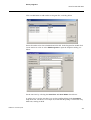
,PSRUWRIDQROG&$3FRQILJXUDWLRQ
Select a terminal in the Navigator, go to the )LOH menu and select ,PSRUW&$3
&RQILJXUDWLRQ. Select an old CAP 531 project.tre file, see below.
In the CAP 531 Navigator select the terminal from which you want to import the configuration. Click the right mouse button and select &RS\7HUPLQDO&RQILJXUDWLRQ.
An arrow appears at the selected terminal as shown below.
36
1MRK 511 142-UEN*1p3rA
&RQILJXUDWLRQRIWHUPLQDOVZLWK&$3
How To Use CAP 540
In the Navigator select the target terminal. Click the right mouse button and select
3DVWH&$3&RQILJXUDWLRQ.
Once the Cap 531 Configuration is pasted, the Cap 531 Navigator displays the copied
terminal with a check mark before it to accentuate the status of the terminal.
Repeat this procedure for all terminals in the CAP 531 project.
1MRK 511 142-UEN*1p3rA
37
2WKHUSURJUDPV
How To Use CAP 540
2WKHUSURJUDPV
In the pull-down menu you find more programs.
7LPH6FKHGXOHU
Is used for Auto Polling i.e. to start Disturbance Handling at predefined times.
You can also decide whether to print the Disturbance by selecting the print-out type in
the $XWR3ULQWbox in the &RPPXQLFDWLRQ6HWWLQJV dialog box, see page 49.
Explanation of letters in Print column.
38
R
Disturbance file REVAL format (.REV)
H
Header file REVAL format (.REH)
D
Disturbance report file (.RSD)
T
Disturbance file COMTRADE format (.DAT)
G
Header file COMTRADE format (.CFG)
No
No Print
1MRK 511 142-UEN*1p3rA
2WKHUSURJUDPV
How To Use CAP 540
Click on Add button to add stations to Program list, see dialog below.
Select all stations to be time scheduled and click OK. In the Program list double click
on one station at a time or select (GLW3URSHUWLHV to open the Properties dialog, see
below.
Set the start time by selecting the 6WDUW+RXU and 6WDUW0LQXWH check boxes.
A quicker way to set the start time is to use the predefined times in the 3HULRGLFLW\
drop down lists. The hours, for example 03, means that the polling is carried out every
third hour, starting at 00:00.
1MRK 511 142-UEN*1p3rA
39
2WKHUSURJUDPV
How To Use CAP 540
Click on menu 6HWWLQJV*HQHUDO to open the General Settings dialog, see below.
The options in the *HQHUDO 6HWWLQJVdialog are described below:
External Trigged Polling
An external event /file triggers the polling.
Time Trigged Polling
The clock triggers the polling (normal function)
Initiate Time Trigged Polling Runs an additional polling in an old SMS010 structure
in additional SMS structure after normal polling.
File SearchingTime Interval The time interval for searching the file when External
Trigged Polling was selected.
Additional SMS Station
Path
The SMS010 path for “Initiate Time Trigged Polling in
an additional SMS structure”.
Click on Start button to start the timer. At the start time the Disturbance Handling Program will start polling all terminals in the station (Station Disturbance Upload).
40
1MRK 511 142-UEN*1p3rA
2WKHUSURJUDPV
How To Use CAP 540
7LPH6\QFKURQL]DWLRQ
Is used when setting up the time synchronization of all terminals in the station connected to the same loop. The time message is sent to all COM ports used by the different stations in the project.
The buttons in the 7LPH6\QFKURQL]DWLRQmenu are described below:
Start Cycling
Manual start of time synchronization cycling (follows the
time cyclicity)
Sync Now
Immediate time synchronization (disregards time cyclicity).
Update Time
The time settings are updated from the PC clock.
Set PC Clock
The PC clock is updated from the time settings.
Exit
Exit from Time Synchronization.
In the 7LPH)RUPDWER[ there are two alternatives, the second option gives more
detailed time information.
In the 7LPH&\FOLFLW\box you set the time interval for the time synchronization.
Ex. 1 Hour and 30 minutes means that time synchronization is performed every
90 minutes.
1MRK 511 142-UEN*1p3rA
41
2WKHUSURJUDPV
How To Use CAP 540
/(',QGLFDWLRQV
Start the LED indications from a terminal node with a right mouse click, see below.
LED Indications is used to show the status of Terminal LED’s. When pressing the
Start/Stop button the communication to the Terminal will start. The communication
will go on continuously until the Start/Stop button is pressed again.
42
1MRK 511 142-UEN*1p3rA
2WKHUSURJUDPV
How To Use CAP 540
(YHQW/LVW
Start Event List from a terminal node with a right mouse click, see below.
Event List is used to show the status of Terminal Events. When pressing the Start button the communication to the Terminal will start reading the Event buffer.
1MRK 511 142-UEN*1p3rA
43
7RROV
How To Use CAP 540
7RROV
7HUPLQDO(PXODWRU
Terminal Emulator is used for fault tracing when setting up the communication. Start
the Terminal Emulator by selecting a terminal in the project structure and then select
Terminal Emulator in the Tools menu.
7HUPLQDO(PXODWRU settings:
44
Send Message
Send a message by typing a SPA code, or use the default
“RF” to check the communication.
Elapsed time
Total time. (Send+Receive)
Send
The program displays the full message that was sent.
Receive
The program displays the full message received.
Respond Time (ms)
Respond time in milliseconds.
Prepared SPA Message
Configures to send short SPA messages.
Full SPA Message
Configures to send full SPA messages.
Other (AT)
Configures to send other commands, normally AT commands to the modem.
Repeat
Number of times the message is sent.
TimeOut
Time out after number of seconds
1MRK 511 142-UEN*1p3rA
7RROV
How To Use CAP 540
There are also two menus in the Terminal Emulator dialog box:
)LOH where you can delete the log file.
9LHZ where you can watch the log file.
The log file is resaved for each sent message and owerwrites the old file.
)LOH&RQYHUVLRQ
Enter which file to convert in the “Source File” field or browse if you need to. Select
the file type you wish to convert to and click on Convert.
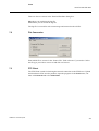
)73&OLHQW
The FTP Client is used for checking the network connection to the FTP Server. Upload
and download of files are also possible. Open the program via the 7RROV menu, continue with 1HWZRUNand select )73&OLHQW.
1MRK 511 142-UEN*1p3rA
45
7RROV
How To Use CAP 540
Items in the )73&OLHQW dialog box:
Server Name
Type in the name of the server to communicate with.
User Name
Type in your own user name on that server.
Password
Type in your password.
Server
Server file list.
Client
Client file list.
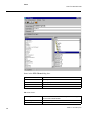
)LOHmenu items:
46
Save Login Data
Saves server name, user name and password settings for
the next FTP Client session.
Delete Log File
Deletes the log file.
Exit
Exit FTP Client.
1MRK 511 142-UEN*1p3rA
7RROV
How To Use CAP 540
&RPPXQLFDWLRQ menu items:
Connect
Connect to the FTP Server
Disconnect
Disconnect from the FTP Server
Upload
Transfer files from client to server.
Download
Transfer files from server to client.
6HWWLQJV menu items:
Protocol
Select FTP or HTTP protocol. The HTTP protocol opens
up an HTML-editor.
Station Log in Data
Retrieves the station log in data for the selected station.
(previously set in Communication settings)
9LHZ menu items:
Log File
View the log file. If the HTTP protocol was selected
above, more menu alternatives are listed.
Release Notes
View the release notes.
8VHUGHILQHGPHQXV
The menu item Customize Menus is used when the user wants to add own menu items
(max 5) to the Tools menu. By clicking on menu Tools/Customize Menus the dialog
below will be displayed.
Add up to five menu items at the bottom of the Tools menu with menu name, program
to be started and visibility which controls the visibility of a menu item depending on
the selected node in the Navigator.
1MRK 511 142-UEN*1p3rA
47
6HWWLQJV
How To Use CAP 540
6HWWLQJV
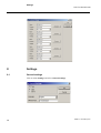
*HQHUDOVHWWLQJV
Click on menu 6HWWLQJV and select *HQHUDO6HWWLQJV.
48
1MRK 511 142-UEN*1p3rA
6HWWLQJV
How To Use CAP 540
PC Type
Select PC type
• Client
Usually a Central PC.
• Server
Usually a Station PC. TCP Server and SPA Server is
started automatically
Language
Select language in the drop down list.
SMS010 Path
Path of SMS 010
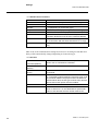
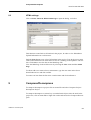
&RPPXQLFDWLRQVHWWLQJV
Click on Settings menu or right click on a station node and select &RPPXQLFDWLRQ
6HWWLQJV. The dialog can only be opened if a station node is selected.
If you have the “Basic version” some alternatives in the dialog box are not applicable.
With the “Remote Connection” option installed, those alternatives are activated.
1MRK 511 142-UEN*1p3rA
49
6HWWLQJV
How To Use CAP 540
• &RPPXQLFDWLRQ3DUDPHWHUV
Serial Port
COM 1 - COM 250
Protocol
SPA, SR10, RAW (only for SMS 010 compability)
Baud Rate
300 - 115200 Baud
Data Bits
7 - 8 (Depending on Connection type)
Parity
ODD, EVEN, NONE (Depending on Connection type)
Echo
IGNORE, NONE, CHECK (only for SMS 010 compability)
Handshake
NONE, RTS-IDLE, RTS/CTS, XON/XOFF (For front-communication RTS-IDLE must be used, otherwise NONE)
TimeOut
Number of seconds before timeout when trying to establish a connection with the terminal and there is no reply.
Retries
Number of attempts to connect in case the terminal is
busy.
Most of the serial communication settings do not have to be changed. Data Bits and
Parity will be automatically changed depending on Connection type.
&RQQHFWLRQ
Central PC-> Station PC
->Terminal (Modem)
50
You work on a Central PC which dials up a Station PC,
which in turn is connected to a terminal.
Central PC-> Terminal
(Modem)
The Central PC is connected to a terminal via modem.
Station PC-> Terminal
(Direct)
There is a direct connection between the Station PC and
the terminal.
Network
Network Connection between a Client PC and a Server
PC. To be able to select Network Connection three conditions must be fulfilled: The project must be located on a
shared network disk, the PC type must be Client and the
Remote Connection option must be installed.
Server Name
Server PC name or IP address
Port Number
The Port number must be equal in Client PC and TCP
Server in Server PC. To view Disturbance Upload Information in web browser the Port number must be 80.
1MRK 511 142-UEN*1p3rA
6HWWLQJV
How To Use CAP 540
• )736HUYHU'DWD
Server Name
FTP Server PC name
User Name
FTP User Id
Password
FTP Password
Default Server File Path
Disturbance files are stored in an identical file structure
on the FTP Server.
Week Directories
The disturbance files are stored on the same path as
below in User Defined, but there is also a directory for
each week of the year.
Example: C:\TEMP\W1...W52
The disturbance files are sorted in the week directories
according to disturbance date.
User Defined
Any given path can be entered for the server (independent of the terminal path).
Send Disturbance Files to Disturbance files are sent to FTP server after disturbance
Server
polling.
Send HTML Files to
Server
HTML files are sent to FTP Server after disturbance polling. HTML files of the disturbance are always created on
the station PC for viewing Disturbance information in a
web browser. The file is overwritten each time by the disturbance polling.
Connection Request Time FTP connection time out in seconds.
Out (s)
• 0RGHP
If you use a modem which is predefined in the 7\SH drop down list you do not have
to change the settings. If you have a modem not included in the list, enter the name
of the modem in the 1HZW\SHfield. In this case you need to make sure that the settings in the ,QLW, &RQQHFWand 1R&RQQHFW fields are correct according to the
modem manual.
1MRK 511 142-UEN*1p3rA
Init
Read the modem manual and enter correct AT commands to establish contact with the modem.
Connect
Read the modem manual and enter correct connect result
codes from the modem.
No Connect
Read the modem manual and enter correct error result
codes from the modem.
Delay (ms)
The time delay between the different AT commands.
Timeout
Indicates number of seconds granted to connect before
there is a connection timeout.
Dial retries
Number of connection retries after timeout.
Phone No
The phone No. to the dial-up station. (Use phone list button for convenience)
51
6HWWLQJV
How To Use CAP 540
Click on $GG0RGHP button to add a new modem.
Click on 5HPRYH0RGHP button to remove the selected modem from the list.
Click on0RGHPLQIR button to get information of modem settings.
Click on 3KRQH/LVW button to open the 3KRQH/LVW dialog box, see below.
To edit an old phone number select a station name, type the new number in the Phone
No text box and click on Edit.
To add a new number type a station name and a phone number in the textboxes and
click on Add.
To remove an item select a station name and click on Remove.
• $XWR3ROOLQJ7LPH6FKHGXOHU
Disturbance and Header
Upload of full disturbance.
Header
Upload of only header.
No Polling
No upload.
Central Polling of
selected station
Possibility to skip polling of this station.
$XWR3ULQW7LPH6FKHGXOHU
52
Disturbance and Header
Print of full disturbance.
Header
Print of header.
No Print
No print.
1MRK 511 142-UEN*1p3rA
6HWWLQJV
How To Use CAP 540
• 'LVWXUEDQFH)LOH)RUPDW
Select the file format REVAL or COMTRADE. The disturbance files are always
stored in REVAL format. If COMTRADE format is selected the REVAL file will be
converted to COMTRADE format and both REVAL and COMTRADE disturbance
files will be stored on the PC disk.
Click on (PDLO6HWWLQJV button to open the Email Settings dialog box, see below.
1MRK 511 142-UEN*1p3rA
53
6HWWLQJV
How To Use CAP 540
Mail Server
Type the server name to mail to.
Subject
Type a subject which characterizes the disturbance.
Email to
Type in the receiver´s Email address.
Email from
Type in your own Email address
Send Disturbance Summary
Send disturbance summary from latest polling as attachment, see example below.
Send Disturbance Files
Send disturbance files from latest polling as attachments.
Send Log Files
Send log files from latest polling as attachments.
Email Filter
When this box is checked Email will only be sent if the
Trig Signal is identical to one of the checked signals in the
Terminal Digital Channels List.
Example of Send Disturbance Summary
54
Station:
Stn 1
Bay:
Bay 1
Terminal:
REL511 V2.0 Line Protection
Terminal type:
REx500 2A
Disturbance Date:
03-11-04
Disturbance Time:
04:55:10.245
Disturbance File:
03110407.REH
Trig:
ZM3-TRIP
Recording Number:
7
Fault type:
L1-N
Fault Location:
37.8%
1MRK 511 142-UEN*1p3rA
&RPSUHVV'HFRPSUHVV
How To Use CAP 540
+70/VHWWLQJV
Click on 7RROV, 1HWZRUN, +70/0DLQ3DJH to open the dialog, see below.
This function creates links to all stations in the project, in order to view Disturbance
Upload Information in a web browser.
Push the 6FDQ button to get a list of all stations in the project. Type in the server name
of the remote Station PC in which the TCP Server is running or local path for each station. Click 6DYH to save the data on the Main Page File.
View the Main Page in the web browser by selecting the 9LHZ menu and then 0DLQ
3DJH.
To edit an old server name select a station name, type the new name in the Server
Name/Path text box and click on Edit.
To remove an item from the list select a station name and click on Remove.
&RPSUHVV'HFRPSUHVV
To compress/decompress a project click on menu File and select Compress Project/
Decompress Project.
To compress/decompress a station, bay or terminal node object select the node in the
project tree, click on menu Edit or right click on the node and select Compress/Decompress.
1MRK 511 142-UEN*1p3rA
55
([LW&$3
How To Use CAP 540
1RWH
7RGHFRPSUHVVDQRGHREMHFWWKHSDUHQWQRGHPXVWEHVHOHFWHG
Different file extensions are used for the node objects:
1RGHREMHFW
)LOHH[WHQVLRQ
Project
.prj
Station
.stn
Bay
.bay
Terminal
.tml
([LW&$3
Click File/Exit to exit CAP 540.
56
1MRK 511 142-UEN*1p3rA
7RROEDUEXWWRQV
Appendix A, Toolbar buttons
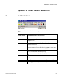
$SSHQGL[$7RROEDUEXWWRQVDQGPHQXV
7RROEDUEXWWRQV
The numbers below the toolbar buttons are represented and explained in the table
below:
1MRK 511 142-UEN*1p3rA
7RROEDU%XWWRQ
1R
7RROEDU%XWWRQ1DPHDQG)XQFWLRQ
1
Open CAP 540 Project.
2
Toggle between the Disturbance File Browser and the regular
Navigator view.
3
Start Disturbance Evaluation program (REVAL).
4
Start Parameter Setting tool, see “Parameter setting” on page 25
for more information.
5
Start Terminal Configuration program, see “How to start CAP
531 from terminal level in CAP 540” on page 35 for more information.
6
Start Time Scheduler program, see page 38 for more information
on the Time Scheduler and Auto polling.
7
Start Terminal Emulator program, see page 44 for more information.
8
Dial
9
Hang-up
10
Display Disturbance Records List to the right of the Navigator.
11
Terminate processes
12
List of logged on users (PC name/User Id)
57
0HQXV
Appendix A, Toolbar buttons
0HQXV
)LOH
0HQX,WHPV
)XQFWLRQ
New Project
Create a new project.
Open Project
Open an old project.
Delete Project
Delete an old project (not the current).
Compress Project
Compress the current project.
Decompress
Project
Decompress an old project.
Import SMS010
Project
Import a project created in SMS010.
Import Cap531
Configuration
Import an old configuration created in Cap 531, terminal by terminal.
Copy Project
Copy the current project.
Convert old Project Convert an old project created in earlier versions of CAP 540 to
support long file names.
Exit
Shut the program down.
(GLW
0HQX,WHPV
)XQFWLRQ
Add
A new node with a default name will be created in the
Navigator.
Remove
Remove the selected node including all it´s contents.
Remove Disturbance Files Remove all disturbance files in the project.
58
Rename
Rename selected node.
Cut
Select a node to be moved.
Copy
Select a node to be copied.
Paste
Move or copy a node.
Move
Select a node to be sorted
Insert
Sort a node
Compress
Compress a station, bay or terminal
Decompress
Decompress a station, bay or terminal
Refresh
Refresh the Navigator.
Properties
List the properties of the selected terminal.
1MRK 511 142-UEN*1p3rA
0HQXV
Appendix A, Toolbar buttons
6HWWLQJV
0HQX,WHPV
)XQFWLRQ
General Settings
Select PC type and language, see page 48 for more
information.
Communication Settings
Start Communication Settings dialog, see page 49
for more information.
3URJUDPV
0HQX,WHPV
)XQFWLRQ
Dial
Dial a predefined phone number.
Hang up
Hang up the connection.
Disturbance Handling
• Station Disturbance upload Upload disturbances of the entire station (all terminals) to Station PC or Central PC, depending on configuration.
1MRK 511 142-UEN*1p3rA
• Station Disturbance File
Transfer
Upload disturbance files from Station PC to Central
PC.
• Terminal Disturbance List
Upload disturbances from terminal to Station PC or
Central PC, depending on configuration.
• Terminal Disturbance File
List
Upload disturbance files from Station PC to Central
PC.
• Manual Trig
Generate a disturbance in the terminal manually.
• Clear LEDs
Manually turn off the yellow LED on the terminal.
• Clear All Recordings
Clear all disturbances in the terminal.
• Disturbance Evaluation
Start Disturbance Evaluation program. Refer to the
REVAL manual for more information.
Parameter Setting
Start Parameter Setting tool, see page 25 for more
information.
Terminal Configuration
Start Terminal Configuration program, see page 35
for more information.
Time Scheduler
Start Time Scheduler program, see “Other programs”
on page 38.
Time Synchronization
Start Time Synchronization program, see page 41 for
more information.
LED Indications
Show terminal LED status, see page 42 for more
information.
Event List
Show terminal events, see page 43 for more information.
59
0HQXV
Appendix A, Toolbar buttons
60
9LHZ
0HQX,WHPV
)XQFWLRQ
Disturbance Records List
Display Disturbance Records List to the right of the
Navigator.
Disturbance File Browser
Display a file system navigator.
Disturbance Communication
Log
Display Disturbance Communication Log
(SPA communication)
Modem Communication Log
Display Modem Communication Log
(Modem communication).
Communication Status Log
Display General Communication Status Log.
General Error Log
Display General Error Log.
6\VWHP
0HQX,WHPV
)XQFWLRQ
Users
This dialog box is for the system administrator and
enables adding and deleting users, see “How to Log
on” on page 18 for more information.
Log On
Open the Log on dialog box, see page 18 for more
information.
Security Mode
Disable all functions in the CAP 540 program.
7RROV
0HQX,WHPV
)XQFWLRQ
Terminate Processes
Ends all processes
SPA Server
This program is only run in a Station PC. The program handles the communication between the
modem port and the SPA port for a Central PC - Station PC connection via modem.
• Modem Port
Select Modem Port in the drop down list.
• SPA Port
Select SPA Port in the drop down list.
• SPA TimeOut
Set the SPA TimeOut in the drop down list.
Terminal Emulator
Start the Terminal Emulator tool, see page 44 for
more information.
File Conversion
Convert files to COMTRADE format, see page 45 for
more information.
1MRK 511 142-UEN*1p3rA
0HQXV
Appendix A, Toolbar buttons
0HQX,WHPV
)XQFWLRQ
Network
• Connect
Connect to Server PC for checking network connection.
• Disconnect
Disconnect from Server PC.
• TCP Server
Start the TCP Server which handles the network
communication in Server PC and transfers HTMLfiles to the client. The TCP Server will be started
automatically if PC type = Server, see page 48 for
more information.
• FTP Client
Start the FTP Client which is used for checking the
network connection to the FTP-server, see page 45
for more information.
• HTML Main Page
Create a main page with links to all stations in the
project to view Disturbance Upload Information in a
web browser, see page 55 for more information.
• Ping
Ping an IP address.
Decompress Zwt
Start CAP 531 to decompress old projects (.zwt)
Customize Menus
Possibility to create up to five user defined menus for
starting optional programs
+HOS
0HQX,WHPV
)XQFWLRQ
Documentation
1MRK 511 142-UEN*1p3rA
• CAP 540 Navigator
CAP 540 User´s Manual
• CAP 531
CAP 531 User´s Manual
• Parameter Setting
PST User´s Manual
• Settings Visualisation
SVT User´s Manual
• Disturbance Evaluation
REVAL User´s Manual
• Modem Info
Modem Info Manual
• Installation and Commissioning
Installation and Commissioning manual
Tutorial
CAP 540 Tutorial
Release Notes
CAP 540 Release Notes
About CAP 540
Version and License Agreement information
61
0HQXV
Appendix A, Toolbar buttons
62
1MRK 511 142-UEN*1p3rA
ABB Automation Technologies AB
License Agreement
NOTICE TO USER: PLEASE READ THIS CONTRACT CAREFULLY. BY USING ALL OR ANY PORTION OF
THE SOFWARE YOU ACCEPT ALL THE TERMS AND CONDITIONS OF THIS AGREEMENT, INCLUDING, IN
PARTICULAR THE LIMITATIONS ON: USE CONTAINED IN SECTION 2; TRANSFERABILITY IN SECTION 4;
WARRANTY IN SECTION 6 AND 7; AND EXPORT RULES IN SECTION 8. YOU AGREE THAT THIS AGREEMENT IS ENFORCEABLE LIKE ANY WRITTEN NEGOTIATED AGREEMENT SIGNED BY YOU. IF YOU DO
NOT AGREE, DO NOT USE THIS SOFTWARE. IF YOU ACQUIRED THE SOFTWARE ON TANGIBLE MEDIA
(e.g. CD) WITHOUT AN OPPORTUNITY TO REVIEW THIS LICENSE AND YOU DO NOT ACCEPT THIS
AGREEMENT, YOU MAY OBTAIN A REFUND OF ANY AMOUNT YOU ORIGINALLY PAID IF YOU: (A) DO NOT
USE THE SOFTWARE AND (B) RETURN IT, WITH PROOF OF PAYMENT, TO THE LOCATION FROM WHICH
IT WAS OBTAINED WITHIN THIRTY (30) DAYS OF THE PURCHASE DATE.
1. Definitions. "Software" means (a) all of the contents of the files, disk(s), CD-ROM(s) or other media with which
this Agreement is provided, including but not limited to (i) ABB or third party computer information or software; (ii)
related explanatory written materials or files ("Documentation"); and (iii) fonts; and (b) upgrades, modified versions, updates, additions, and copies of the Software, if any, licensed to you by ABB (collectively, "Updates").
"Use" or "Using" means to access, install, download, copy or otherwise benefit from using the functionality of the
Software in accordance with the Documentation. "Permitted Number" means one (1) unless otherwise indicated
under a valid license (e.g. Corporate Software License) granted by ABB. "Computer" means an electronic device
that accepts information in digital or similar form and manipulates it for a specific result based on a sequence of
instructions. "Terminal" means protection and control terminal with serial communication supported by the Software. By "ABB" this document is referring to ABB Automation Technologies AB, Substation Automation, Västerås,
Sweden.
2. Software License. As long as you comply with the terms of this Software License Agreement (this "Agreement"), ABB grants to you a non-exclusive license to Use the Software for the purposes described in the Documentation. Some third party materials included in the Software may be subject to other terms and conditions,
which are typically found in a "Read Me" file located near such materials.
2.1. General Use. You may install and Use a copy of the Software on your compatible computer, up to the Permitted Number of computers.
2.1.1. Single License. The Single Software License Agreement grants the user to install the software on a single
corporate computer.
2.1.2. Corporate License. Customers with a Corporate License are granted to install the software on any number
of corporate computers without a limitation on the maximum Permitted Number of computers.
2.2. Backup Copy. With Single Licence you may make one backup copy of the Software, provided your backup
copy is not installed or used on any computer. You may not transfer the rights to a backup copy unless you transfer
all rights in the Software as provided under Section 4. The Corporate License grants the User to make backup
copies of the software without limitation to the maximum Permitted Number.
2.3. Home Use. You, as the primary user of the computer on which the Software is installed, may also install the
Software on one of your home computers. However, the Software may not be used on your home computer at the
same time the Software on the primary computer is being used.
2.4. No Modification. You may customize or extend the functionality of the installer for the Software as specifically
allowed by instructions found at www.abb.com/substationautomation or (e.g., installation of additional plug-in and
help files). You may not otherwise alter or modify the Software or create a new installer for the Software. The Software is licensed and distributed by ABB for viewing, changing and up/downloading parameters and configuration
files for ABB's terminals. You are not authorized to integrate or use the Software with any other software.
3. Intellectual Property Rights. The Software and any copies that you are authorized by ABB to make are the
intellectual property of and are owned by ABB. The structure, organization and code of the Software are the valuable trade secrets and confidential information of ABB and its suppliers. You may not copy the Software, except as
set forth in Section 2 ("Software License"). Any copies that you are permitted to make pursuant to this Agreement
must contain the same copyright and other proprietary notices that appear on or in the Software. Unless specifically and expressly permitted by ABB, you agree not to modify, adapt or translate the Software. You also agree not
to reverse engineer, de-compile, disassemble or otherwise attempt to discover the source code of the Software.
Trademarks shall be used in accordance with accepted trademark practice, including identification of trademarks
owners’ names. Trademarks can only be used to identify printed output produced by the Software and such use of
any trademark does not give you any rights of ownership in that trademark. Except as expressly stated herein, this
Agreement does not grant you any intellectual property rights in the Software and all rights not expressly granted
herein are reserved by ABB.
4. Transfer. You may not, rent, lease, sublicense or authorize all or any portion of the Software to be copied onto
another user’s computer except as may be expressly permitted herein. You may, however, transfer all your rights
to Use the Software to another person or legal entity provided that: (a) you also transfer this Agreement, the Software and all other software or hardware bundled or pre-installed with the Software, including all copies, Updates
and prior versions, and all copies of data files, to such person or entity; (b) you retain no copies, including backups
and copies stored on a computer; and (c) the receiving party accepts the terms and conditions of this Agreement
and any other terms and conditions upon which you legally purchased a license to the Software. Notwithstanding
the foregoing, you may not transfer education, pre-release, or not for resale copies of the Software.
5. Multiple Environment Software / Multiple Language Software / Dual Media Software / Multiple Copies/ Bundles / Updates. If the Software supports multiple platforms or languages, if you receive the Software on multiple
media, if you otherwise receive multiple copies of the Software, or if you received the Software bundled with other
software, the total number of your computers on which all versions of the Software are installed may not exceed
the Permitted Number. You may not, rent, lease, sublicense, lend or transfer any versions or copies of such Software you do not Use. If the Software is an Update to a previous version of the Software, you must possess a valid
license to such previous version in order to Use the Update. You may continue to Use the previous version of the
Software on your computer after you receive the Update to assist you in the transition to the Update, provided that:
the Update and the previous version are installed on the same computer; the previous version or copies thereof
are not transferred to another party or computer unless all copies of the Update are also transferred to such party
or computer; and you acknowledge that any obligation ABB may have to support the previous version of the Software may be ended upon availability of the Update.
6. Pre-release Product Additional Terms. If the product you have received with this license is pre-commercial
release or beta Software ("Pre-release Software"), then the following Section applies. To the extent that any provision in this Section is in conflict with any other term or condition in this Agreement, this Section shall supersede
such other term(s) and condition(s) with respect to the Pre-release Software, but only to the extent necessary to
resolve the conflict. You acknowledge that the Software is a pre-release version, does not represent final product
from ABB, and may contain bugs, errors and other problems that could cause system or other failures and data
loss. Consequently, the Pre-release Software is provided to you "AS-IS", and ABB disclaims any warranty or liability obligations to you of any kind. WHERE LEGALLY LIABILITY CANNOT BE EXCLUDED FOR PRE-RELEASE
SOFTWARE, BUT IT MAY BE LIMITED, ABB’S LIABILITY AND THAT OF ITS SUPPLIERS SHALL BE LIMITED
TO THE SUM OF FIFTY DOLLARS (U.S. $50) IN TOTAL. You acknowledge that ABB has not promised or guaranteed to you that Pre-release Software will be announced or made available to anyone in the future, that ABB has
no express or implied obligation to you to announce or introduce the Pre-release Software and that ABB may not
introduce a product similar to or compatible with the Pre-release Software. Accordingly, you acknowledge that any
research or development that you perform regarding the Pre-release Software or any product associated with the
Pre-release Software is done entirely at your own risk. During the term of this Agreement, if requested by ABB,
you will provide feedback to ABB regarding testing and use of the Pre-release Software, including error or bug
reports. If you have been provided the Pre-release Software pursuant to a separate written agreement, such as an
ABB Agreement for Unreleased Products, your use of the Software is also governed by such agreement. You
agree that you may not and certify that you will not sublicense, lease, loan, rent, or transfer the Pre-release Software. Upon receipt of a later unreleased version of the Pre-release Software or release by ABB of a publicly
released commercial version of the Software, whether as a stand-alone product or as part of a larger product, you
agree to return or destroy all earlier Pre-release Software received from ABB and to abide by the terms of the User
License Agreement for any such later versions of the Pre-release Software. Pre-release software may be delivered separately or together or as part of a released product.
7.LIMITATION OF LIABILITY. ABB IS NOT LIABLE FOR ANY DAMAGES TO YOUR PC AND/OR LAN (LOCAL
AREA NETWORK) CAUSED BY THE SOFTWARE. IN NO EVENT WILL ABB OR ITS SUPPLIERS BE LIABLE
TO YOU FOR ANY DAMAGES, CLAIMS OR COSTS WHATSOEVER OR ANY CONSEQUENTIAL, INDIRECT,
INCIDENTAL DAMAGES, OR ANY LOST PROFITS, SAVINGS, BUSINESS, REVENUE, GOODWILL, ANTICI-
PATED SAVINGS, EVEN IF AN ABB REPRESENTATIVE HAS BEEN ADVISED OF THE POSSIBILITY OF SUCH
LOSS, DAMAGES, CLAIMS OR COSTS OR FOR ANY CLAIM BY ANY THIRD PARTY, FITNESS FOR A PARTICULAR PURPOSE. THE FOREGOING LIMITATIONS AND EXCLUSIONS APPLY TO THE EXTENT PERMITTED BY APPLICABLE LAW IN YOUR JURISDICTION. ABB’S AGGREGATE LIABILITY AND THAT OF ITS
SUPPLIERS UNDER OR IN CONNECTION WITH THIS AGREEMENT SHALL BE LIMITED TO THE AMOUNT
PAID FOR THE SOFTWARE.
8. Export Rules. You agree that the Software will not be shipped, transferred or exported into any country or used
in any manner prohibited by the United States Export Administration Act or any other export laws, restrictions or
regulations (collectively the "Export Laws"). In addition, if the Software is identified as export controlled items
under the Export Laws, you represent and warrant that you are not a citizen, or otherwise located within, an
embargoed nation (including without limitation Iran, Iraq, Syria, Sudan, Libya, Cuba, North Korea, and Serbia) and
that you are not otherwise prohibited under the Export Laws from receiving the Software. It is expressly agreed
that the Software shall not be used by you for planning, construction, maintenance, operation or use, directly or
indirectly, in nuclear power plants, missile technology, chemical or biological weapons applications or flight, navigation or communication of aircraft or ground support equipment. All rights to Use the Software are granted on
condition that such rights are forfeited if you fail to comply with the terms of this Agreement.
The interpretation and application of these licence terms and conditions shall be governed by the laws of Sweden.
Disputes between you and ABB arising from these licence terms and conditions shall be resolved by a Swedish
court, in the first instance by the Stockholm District Court.
If you have any questions regarding this Agreement or if you wish to request any information from ABB please use
the address and contact information included with this product to contact the ABB office serving your jurisdiction.
1MRK 511 142-UEN
$%%$XWRPDWLRQ7HFKQRORJLHV$%
Substation Automation
SE-721 59 Västerås
Sweden
Telephone: +46 (0) 21 34 20 00
Facsimile: +46 (0) 21 14 69 18
Internet: www.abb.com/substationautomation
Printed on recycled and ecolabelled paper