1
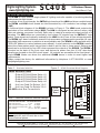
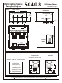
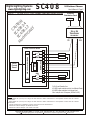
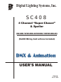
Digital Lighting Systems, Inc.
SC408
4 Channel “Super-Chaser”
& Speller
(SC408-12/SC408-24/SC408-120/SC408-22)
(SL408 Wiring Instructions Included)
USER'S MANUAL
SC408-UM
Rev. E - 04/03
Digital Lighting Systems
www.digitallighting.com
SC408
16 Pattern Chaser
User's Manual - Page1 1
General Description
The SC408 is a four-channel single-phase AC lighting controller capable of producing dazzling
and spectacular light shows.
It consists of two circuit boards, the INT04 logic board and the LDM load driver module board.
The INT04 and LDM circuit boards are interconnected by a 10-conductor low-voltage cable
(LVC).
A functional block diagram of the SC408 is shown in Figure 1. The LDM board contains the
equivalent of four solid-state relays (SSR) The LDM is configured as two pairs of relays, with
each pair sharing one power line feed. Each relay is rated at a maximum output current of 8
Amperes. The SSR relays are controlled by low-voltage DC signals from the INT04 SC logic
board. These signals are optically-isolated by the LDM circuitry from all line voltage elements.
The INT04 logic board contains a powerful microprocessor programmed to generate 16 userselectable light sequences or patterns at an adjustable rate (the SC408 is also available with a
“SPELLER” pattern or custom patterns upon request). A rotary selector on the INT04 is used to
select the chase pattern and a second one is used to set the rate or chase speed. Patterns and
speed can be monitored by four LED's that represent the outputs of the SC408. The INT04 is
mounted on the back of the front cover and derives its power from the 10 VAC step down
transformer located on the LDM circuit board. All controls are accessible at the front panel. A
single SC408 Master can drive four additional SL408 slaves in order to meet higher load
requirements.
Please contact the factory for additional information by telephone 1-877-264-8391 or email
[email protected]
Figure 1 - SC408 Functional Block Diagram
NAME DESCRIPTION
LDM Load Driver Module
2
SSR2
SSR3
Terminal Maximum
Relay Load Current
1 to 4
Input Current For Relays 1 & 2 H1
Input Current For Relays 3 & 4 H2
Input Voltage
H1-H2
1
NEUTRAL BUS
INT04
Control
Board
Table 2 - Absolute Maximum Electrical Ratings
Electrical Characteristic
H1
SSR1
SSR's OPTICAL ISOLATORS
1
Output Of Solid-State Relay #1
2
Output Of Solid-State Relay #2
3
Output Of Solid-State Relay #3
4
Output Of Solid-State Relay #4
H1
Hot Line Feed For Relays 1 & 2
H2
Hot Line Feed For Relays 3 & 4
N1-N6 Neutral Bus Connections.
10 VAC
Transformer
Table 1 - Terminals Definition
N1
N2
N3
N4
N5
N6
3
8 Amps.
20 Amps.
20 Amps.
240 VAC, 1-Phase.
SSR4
4
H2
J3
NOTE
Line Inputs H1 and H2 must be on the
same electrical phase.
7588 NW 8th Street, Miami, Fl. 33126
Copyright
8 pin Connector for Slave units
Tel: 305-264-8391 or 1-877-264-8391
Fax: 305-261-6637
2003 Digital Lighting Systems, All rights Reserved Specifications are subject to change without notice. Printed in U.S.A.
SC408
Digital Lighting Systems
www.digitallighting.com
16 Pattern Chaser
User's Manual - Page1 2
Figure 2 - SC408 Detail
Bottom View
8.30"
(211 mm)
1/2” and 3/4” Conduit Knockouts
Top View
J1
Data
Only
1.9"
(48 mm)
2"
(51 mm)
2.15"
(55 mm)
Low Voltage Ports
4.12"
(105 mm)
2"
(51 mm)
1.150"
(29 mm)
8-Position
2.15"
(55 mm)
1.575"
1.500"
1.500"
(40 mm) (38 mm) (38 mm)
5" (127 mm)
SC408 ( LDM) Load Driver Module
N1 N2 N3 N4 N5 N6
3 4 H2
T1
T4
1
3
2
4
INT04
11.75" (298 mm)
11.07" (281 mm)
H1 1 2
S2 S1
LED OUTPUT
MONITORS
T2
LED's
W1
J3
10 VAC
Transformer
8
Pattern and Speed
Selectors
1 2 3 4
OPTO-ISOLATORS
1
2
3
W2
J1
1 10
5" (127 mm)
4
T3
J2
1 10
1
SC408 Front Cover
J1
Figure 3 - SC408 INT04
Components Side
Solder Side
(Components with dashed outline
are mounted on the rear of the board)
Table 3 - INT04 Circuit Legend
2
4
1
5
5
6
F 012
D
BC E
F 012
D
BC E
S2
789A
Copyright
3
1
789A
7588 NW 8th Street, Miami, Fl. 33126
4
3456
Microprocessor.
Nonvolatile Memory.
Communications Chip.
Quartz Crystal.
Power Supply Capacitor.
Voltage Regulator.
Signal & Power Connector.
Output LED Monitors.
Speed/Pattern Selectors.
INT04
3
2
3456
1
2
3
4
5
6
7
8
S1-2
INT04
S1
S1
S2
8
8
S3
7
Tel: 305-264-8391 or 1-877-264-8391
6
7
Fax: 305-261-6637
2003 Digital Lighting Systems, All rights Reserved Specifications are subject to change without notice. Printed in U.S.A.
Digital Lighting Systems
www.digitallighting.com
SC408
16 Pattern Chaser
User's Manual - Page1 3
A- ENCLOSURE INSTALLATION
Install the SC408 enclosure in a well ventilated area where the ambient temperature will remain
between 40ºF and 104ºF for full load operation. The enclosure location can be near the electric service
panel or close to the loads, whichever is more convenient.
B- LINE VOLTAGE WIRING
(Please refer to Figures 5, 6 & 7)
All Line and Neutral wires must have adequate gauges to carry the load and
the common currents.
All wires must have Copper Conductors with 90ºC Wire Insulation.
!
!
!
!
!
!
Select two 20-Amp. breakers from the same 120 VAC phase in the service panel.
Connect the above breakers to terminals H1 & H2 respectively. If the total load does not exceed
16 Amps., a single breaker may be used and terminals H1 & H2 may be jumpered together with a
#12 AWG wire.
Connect 2 Neutral wires from the service panel to N3 & N4 respectively.
Bring a Common wire and a Return wire, from each of the loads to the SC408. A single Common
wire may be used provided the wire gauge is adequate for carrying the required total load
current.
Connect the Common wires from load #1 through load #4 to any position on the Neutral Bus (N1
- N6).
Connect the Return wires from load #1 through load #4 to terminals 1 through 4 respectively.
C- MASTER-SLAVE SYSTEM WIRING
The SC408 can control four additional SL408 slave units. The slaves contain the Load Driver Module
(LDM) without the INT04 logic control board. This configuration is helpful when the load capacity of the
SC408 master is exceeded and all loads must be synchronized together. The slave is daisy-chained to
the master via low-voltage 5-conductor cables (JJ88) provided by the factory. The SC408 and SL408
are wired identically.
Section A
Loads 1 to 4
Section B
Loads 1 to 4
Section C
Loads 1 to 4
MASTER
SLAVE
SLAVE
SC408
SL408
SL408
1 2 3 4
JJ88
Low Voltage
Control Cable
J1
J1
J2
Figure 4 - SC408 to Sl408 - Master/Slave Connection
7588 NW 8th Street, Miami, Fl. 33126
Copyright
Tel: 305-264-8391 or 1-877-264-8391
J1
J2
To additional Slaves
Fax: 305-261-6637
2003 Digital Lighting Systems, All rights Reserved Specifications are subject to change without notice. Printed in U.S.A.
SC408
Digital Lighting Systems
www.digitallighting.com
16 Pattern Chaser
User's Manual - Page1 4
SC408-120 General Wiring Instructions for 120V version.
Wiring Notes
0 DO NOT EXCEED 960 W (8 Amps. ) per circuit output @ 120VAC.
0 SC408 chaser packs may be fed by one or two 20 A (maximum) branch circuits and may have up to four
separately switched loads.
0 Both breakers must be on the same power phase.
0 CAUTION: DO NOT attempt to parallel outputs to increase capacity.
0 Installations must conform to local and/or NEC code requirements.
0 Each load must have its own Neutral wire for full load operation.
0 All line voltage wires must have copper conductors of adequate Gauge with 90° C wire insulation.
NOTE
The SL408 output wiring is identical to the SC408. SL408 slaves do not have the INT04 control board.
The SL408 Load Driver Board (LDM) does not have a transformer.
Earth Ground
LDM Load Driver Module
SSR2
ON
1
LOAD #1
2
LOAD #2
NEUTRAL BUS
N1
10 VAC
Transformer
INT04
Control
Board
Electrical
Distribution Panel
H1
SSR1
SSR's OPTICAL ISOLATORS
SC C
A
M 408 UT
od -1 IO
el 20 N
sO V
NL AC
Y
Figure 5 - SC408 Typical 120 VAC Wiring.
SSR3
SSR4
N2
N3
N4
N5
ON
2x20 A - 120 VAC
Breakers
On Same Phase
To Distribution Panel
Neutral Bus
N6
3
LOAD #3
4
LOAD #4
H2
For Full Load Operation Use:
#12 AWG copper conductor wire for Line & Neutral Feeds.
#14 AWG copper conductors in/out to each load.
Max. Load: 8 Amperes (960W at 120 VAC).
7588 NW 8th Street, Miami, Fl. 33126
Copyright
Tel: 305-264-8391 or 1-877-264-8391
Fax: 305-261-6637
2003 Digital Lighting Systems, All rights Reserved Specifications are subject to change without notice. Printed in U.S.A.
SC408
Digital Lighting Systems
www.digitallighting.com
16 Pattern Chaser
User's Manual - Page1 5
SC408-220 General Wiring Instructions for 220-240V version.
Wiring Notes
0 DO NOT EXCEED 1920 W (8 Amps. ) per circuit output @ 240VAC.
0 SC408 chaser packs may be fed by one or two 20 A (maximum) branch circuits and may have up to four
separately switched loads.
0 Both breakers must be on the same power phase.
0 CAUTION: DO NOT attempt to parallel outputs to increase capacity.
0 Installations must conform to local and/or NEC code requirements.
0 Each load must have its own Neutral wire for full load operation.
0 All line voltage wires must have copper conductors of adequate Gauge with 90° C wire insulation.
NOTE
The SL408 output wiring is identical to the SC408. SL408 slaves do not have the INT04 control board.
The SL408 Load Driver Board (LDM) does not have a transformer.
Earth Ground
LDM Load Driver Module
SSR2
ON
1
LOAD #1
2
LOAD #2
NEUTRAL BUS
N1
10 VAC
Transformer
INT04
Control
Board
Electrical
Distribution Panel
H1
SSR1
SSR's OPTICAL ISOLATORS
SC C
A
M 408 UT
od -2 IO
el 20 N
sO V
NL AC
Y
Figure 5 - SC408 Typical 220 VAC Wiring.
SSR3
SSR4
N2
N3
N4
N5
ON
2x20 A - 220 VAC
Breakers
On Same Phase
To Distribution Panel
Neutral Bus
N6
3
LOAD #3
4
LOAD #4
H2
For Full Load Operation Use:
#12 AWG copper conductor wire for Line & Neutral Feeds.
#14 AWG copper conductors in/out to each load.
Max. Load: 8 Amperes (1920W at 240 VAC).
7588 NW 8th Street, Miami, Fl. 33126
Copyright
Tel: 305-264-8391 or 1-877-264-8391
Fax: 305-261-6637
2003 Digital Lighting Systems, All rights Reserved Specifications are subject to change without notice. Printed in U.S.A.
www.digitallighting.com
16 Pattern Chaser
Figure 7 - SC408-24/12 Low Voltage Load and Power Wiring
User's Manual - Page1 6
Electrical
Distribution Panel
C
SC AU
TIO
S
4
M C4 08 N
od 0 -2
el 8-1 4
sO 2
NL
Y
NEUTRAL
ON
SC408
Digital Lighting Systems
PRIMARY
24v or 12v
Transformer
SECONDARY
X1
X4
LDM Load Driver Module
H1
SSR2
1
LOAD #1
2
LOAD #2
NEUTRAL BUS
N1
Voltage Divider
Network
INT04
Control
Board
SSR's OPTICAL ISOLATORS
SSR1
SSR3
SSR4
N2
N3
N4
N5
N6
3
LOAD #3
4
LOAD #4
H2
For Full Load Operation Use:
#12 AWG copper conductor wire for Line & Neutral Feeds.
#14 AWG copper conductors in/out to each load.
Max. Load per circuit : 8 Amperes (192W at 24 VAC).
NOTES
1 With SC408-24 you may use a single 24 VAC-800 VA or better transformer or two separate 24 VAC-400 VA or better
transformers.
2 With SC408-12 you may use a single 12 VAC-400 VA or better transformer or two separate 12 VAC-200 VA or better
transformers.
3 Follow transformer's installation & wiring instructions from manufacturer.
4 Maximum Load Per Output: 96 Watts at 12 VAC.
5 Maximum Load Per Output: 192 watts at 24 VAC.
7588 NW 8th Street, Miami, Fl. 33126
Copyright
Tel: 305-264-8391 or 1-877-264-8391
Fax: 305-261-6637
2003 Digital Lighting Systems, All rights Reserved Specifications are subject to change without notice. Printed in U.S.A.
Digital Lighting Systems
www.digitallighting.com
SC408
16 Pattern Chaser
User's Manual - Page1 7
Controls
The controls consist of two rotary 16-position (0-9 and A-F) selectors. S2 (Mode) is
used for selecting the desired chase pattern. Positions 0 and F contain special patterns.
The SC408 outputs can be turned to static ON by selecting F. When 0 is selected, the
SC408 goes into an automatic pattern change mode. All other positions cause the
SC408 to play a single pattern indefinitely. S1 is used to select one of 16 individual
chase rates (Rate). Minimum speed is achieved by selecting position 0. Speed doubles
with each subsequent selector position.
Indicators
LED indicators 1 to 4 indicate the status (On-Off) of their corresponding outputs.
Figure 9 - SC408 Front Panel Indicators and Control Selectors
INT16 Control Board
Mounted On Back Side
S2
S1
Rate
Mode
LED’s
1 2 3 4
CAUTION
Use a small screw
d r i v e r f o r
a d j u s t i n g
selector positions
in order to avoid
damaging the
tips.
Output
Indicators
7588 NW 8th Street, Miami, Fl. 33126
Copyright
Tel: 305-264-8391 or 1-877-264-8391
Fax: 305-261-6637
2003 Digital Lighting Systems, All rights Reserved Specifications are subject to change without notice. Printed in U.S.A.
Digital Lighting Systems
www.digitallighting.com
SC408
16 Pattern Chaser
User's Manual - Page1 8
Patterns for SC408
1
Light Chase
1
2
Fill & Swipe Forward
3
Fill & Swipe Back
5
4
Light Bounce
Dark Bounce
A
Circuits
2 3 4
Step 1:
Step 2:
Step 3:
Step 4:
Step 5:
Step 6:
Step 7:
Step 8:
6
7
8
9
Dark Chase
Flip-Flop
Flash All
Flash Light Chase
B
Spring Back
C
Flash Dark Chase
D
Crawl Forward
Spring Forward
E
F
Crawl Back
All On
0
Auto Cycle
Patterns 1-F
4 x each
then repeat
7588 NW 8th Street, Miami, Fl. 33126
Copyright
KEY:
ON
OFF
Tel: 305-264-8391 or 1-877-264-8391
Fax: 305-261-6637
2003 Digital Lighting Systems, All rights Reserved Specifications are subject to change without notice. Printed in U.S.A.
LIMITED WARRANTY
Digital Lighting Systems, warrants to the purchaser that its
products have been carefully manufactured and inspected and
are warranted to be free from defects of workmanship and
materials when used as intended. Any abuse or misuse contrary
to normal operation shall void this warranty.
Upon request, replacement unit(s) will be shipped as soon as
available. Unless immediate shipment of replacement
merchandise is requested, Digital Lighting Systems will not
ship replacement merchandise until defective merchandise is
received, inspected, and determined to be defective.
Digital Lighting Systems' obligation under this warranty shall be
limited to replacement or repair of any units as shall within one
year of date of invoice from Digital Lighting Systems, prove
defective; and Digital Lighting Systems shall not be liable for
any other damages, whether direct or consequential. The
implied warranties of merchantability and fitness for a
particular purpose are limited to the duration of the
expressed warranty. Some states do not allow the exclusion of
the limitation of incidental or consequential damages, so the
above limitation or exclusion may not apply to you. This
warranty gives you specific legal rights, you may also have other
legal rights which vary from state to state.
No labor charges in connection with warranty problems will
be reimbursed by Digital Lighting Systems without prior
written approval from the factory.
Defective merchandise may be returned to Digital Lighting
Systems, prepaid, after prior notification has been given and
approval obtained for the return. To obtain prior approval for the
return of the defective items, contact your local Digital Lighting
Systems distributor, representative, or:
Digital Lighting Systems, Inc.
Attn: Customer Service Department
7588 NW 8th Street
Miami, FL 33126
(305) 264-8391
Digital Lighting Systems distributors and representatives have
no authority to change this warranty without written permission.
Digital Lighting Systems reserves the right to determine the
best method of correcting warranty problems.
Digital Lighting Systems, Inc.
7588 NW 8th Street
Miami, FL 33126
www.digitallighting.com
Tel
Fax
e-m
305-264-8391
305-261-6637
[email protected]
Printed in U.S.A.
April 2003