1
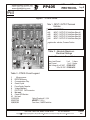
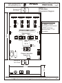
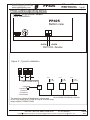
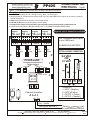
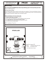
Digital Lighting Systems, Inc.
PROTOCOL
PP405
Four Dimmer or Switch Packs
4 x 5 A. Inputs / 4 x 5 A. outputs 12VDC and 24 VDC
USER'S MANUAL
PP405-UM
04/08
Digital Lighting Systems, Inc.
www.digitallighting.com
PP405
4-Channel Dimmer Pack
PROTOCOL
Page 1
GENERAL DESCRIPTION
The PP405 is a 4-channel PROTOCOL compatible dimmer pack. It is
equivalent to four solid-state relays (SSR's) and a INT04 Logic assembled
on a single circuit board. Power is fed to the PP405-DMX from FOUR 5
Amps. DC Voltage Power Supplies . Each solid state relay is rated for a
maximum output current of 5 amperes. The PP405 has an open frame U
shaped enclosure. The logic signals are optically-isolated from all line
voltage elements. An external step-down 120 VAC to 8 - 12 VAC/ 300mA
transformer is required to supply power to the Logic of the PP405.
ThePROTOCOL DATA BUS control cable is hardwired to the PP405. Several
Dimmer packs may be daisy-chained together. Each PP405 may be easily
set to a unique address with 2 hexadecimal selectors Each of the PP405
outputs may be independently configured to dim or switch from the PSCXX
wall stations.
PP405 is available PP405-12DC for operation in ( 8VDC to 15 VDC range)
and PP405-24 DC for operation in ( 18VDC to 28 VDC range ) to provide full
range dimming to LEDs and other VDC loads.
SWITCHING ONLY LOCK - (See Page 6 for more information)
A PP405 maybe locked by a hardware jumper into switching only. . Please see
Page6 for location of this jumper.
12302 SW 128th Court, Miami, Florida 33186
Copyright
Tel: 305-969-8442
2003 Digital Lighting Systems, All rights Reserved Specifications are subject to change without notice. Printed in U.S.A.
PP405-UM
04/08
Digital Lighting Systems, Inc.
PP405
www.digitallighting.com
4-Channel Dimmer Pack
PROTOCOL
Page 2
PP405
Figure 1 - PP405 Detail
CH 1
16
19
CH 2
CH 3
20
Table 1 - INPUT / OUTPUT Terminals
Definition
CH 4
21
22
17
NAME
CH 1
CH 2
CH 3
CH 4
DESCRIPTION
INPUT / OUTPUT Of Solid-State Relay #1
INPUT / OUTPUT Of Solid-State Relay #2
INPUT / OUTPUT Of Solid-State Relay #3
INPUT / OUTPUT Of Solid-State Relay #4
Negative side switches, Common Positive
11
12 2
13
3
15
14
18
Table 2 - Absolute Maximum
Electrical Ratings
1
S3
6
Electrical Characteristic TerminalMaximum
S1 4
S2
10
9
5
8
7
Relay Load Current
Input Current
Input Voltage 8 to12 VDC
Or
20 to 26 VDC
1 to 4 5 Amps.
1 to 4 5 Amps.
PP405-12DC
PP405-24DC
Table 3 - PP405 Circuit Legend
1
Microprocessor.
2
EEPROM Memory
3
Communications Chip.
4
Quartz Crystal.
5
Power Supply Capacitor.
6
Voltage Regulator.
7
PROTOCOL DATA connector.
8
Not used
9
Output LED Monitors.
10 Not used
11,12,13,14
Optical Couplers # 1,2,3,4
15,16,17,18
MOSFET # 1,2,3,4
19,20,21,22
Fuse 5mm ,5 AMPS fast blow
12302 SW 128th Court, Miami, Florida 33186
Copyright
Tel: 305-969-8442
2003 Digital Lighting Systems, All rights Reserved Specifications are subject to change without notice. Printed in U.S.A.
PP405-UM
04/08
Digital Lighting Systems, Inc.
PP405
www.digitallighting.com
Ch: 2
Ch: 3
Mechanical Installation
PP405-DMX-xxDC
3
6.25 in
Optocouplers
1
2
3
EEPROM
Memory
1
Page 3
Ch: 4
5 A.
Fuse
2
PROTOCOL
Figure 3 PP405-DMX
Dimensional Diagram
Mounting hole
For # 6 screw
Ch: 1
4-Channel Dimmer Pack
V1.0
DE
DE
BC
9A
78
BC
F 0 12
3 45 6
3 45 6
9A
78
-
F 0 12
4
High
address
Microprocessor
S2
4
RS485
Communication
INT04
The PP405 modules
are designed to be mounted
in NEMA enclosures
Mounting Holes : 7” O.C.
( by others).
S1
Channel Indicators
1
D- D+
Mounting hole
For # 6 screw
1.50 in
4.30 in
12302 SW 128th Court, Miami, Florida 33186
Copyright
Tel: 305-969-8442
2003 Digital Lighting Systems, All rights Reserved Specifications are subject to change without notice. Printed in U.S.A.
PP405-UM
04/08
Digital Lighting Systems, Inc.
4-Channel Dimmer Pack
PP405
www.digitallighting.com
PROTOCOL
Page 4
PP405 Control Logic Wiring Methods
Figure 4 PP405 Dimmer Network
Ports Connections.
PP405
Buttom view
- DATA
+DATA
PROTOCOL Data Bus
Figure 5 - Typical Installation
INPUTS
INPUTS
To Loads
9 VAC POWER & DATA
PP405
9 VAC
External Power
Transformer
(For Stations &
Control Modules)
INPUTS
To Loads
PP405
To Loads
PP405
DB44
2 Twisted-Pair (4-Wire) Network Cable
May be GENERAL CABLE #C3362 or Equivalent
The same Low voltage AC transformer could be used
for the logic supply of all PP405 as long as it has the Amps
rating required ( 200MA/ PP405)
12302 SW 128th Court, Miami, Florida 33186
Copyright
Tel: 305-969-8442
2003 Digital Lighting Systems, All rights Reserved Specifications are subject to change without notice. Printed in U.S.A.
PP405-UM
04/08
Digital Lighting Systems, Inc.
4-Channel Dimmer Pack
PP405
www.digitallighting.com
PROTOCOL
Page 5
Figure 9 - PP405-DMX-24DC/PP405-DMX-12DC GENERAL WIRING INSTRUCTIONS:
Wiring Notes
0 DO NOT EXCEED 120W @ 24 VDC or 60 W @ 12 VDC (5 Amps. ) per dimmer output
0 All wiring between the controller and other dimmers (DATA bus) is low voltage (NEMA Class 2) and may be run with One, twisted pair,
shielded #22 AWG wire.
0 PP405-DMXdimmer Modules may be fed by 4 Class 2 Power supplies
0 CAUTION: DO NOT attempt to parallel outputs to increase capacity.
0 Installation must conform to local and/or NEC code requirements and must be performed by a qualified electrician.
0 POWER EACH LOAD DIRECTLY BEFORE CONNECTING IT TO THE PP405 TO ENSURE PROPER WIRING.
Power
supply
#2
IN OUT
-
- -
+
Ch: 1
Power
supply
#3
IN OUT
IN OUT
- -
+
Ch: 2
5 A.
Fuse
Power
supply
#4
IN OUT
- -
+
Ch: 3
5 A.
Fuse
-
+
Ch: 4
5 A.
Fuse
5 A.
Fuse
PP405-xxDC
2
Negative side is dimmed or switched
3
Optocouplers
USE 4 independent power supplies
of up to 5 AMPS each.
The NEGATIVE IS SWITCHED
TYPICAL CHANNEL CONNECTION
24 VDC
OR
12 VDC
+
LOAD
Power
supply
#1
IN
1
2
3
1
RS485
Communication
INT04
V1.0
4
4
1
DE
BC
9A
78
BC
78
9A
-
F 0 12
34 56
F 0 12
3456
DE
Microprocessor
S2
- + + -
S1
Channel Indicators
1
D- D+
2
3
4
- ++ -
TERMINAL #
1 = INPUT - (Negative )
2 = INPUT +(Positive )
3 = OUTPUT + ( Positive )
4 = OUTPUT - ( Negative )
Violet + DATA
Copyright
PROTOCOL DATA BUS
Connect to other PROTOCOL devices
Red - DATA
Tel: 305-969-8442
12302 SW 128th Court, Miami, Florida 33186
PP405-UM
2003 Digital Lighting Systems, All rights Reserved Specifications are subject to change without notice. Printed in U.S.A.
04/08
Digital Lighting Systems, Inc.
4-Channel Dimmer Pack
PP405
www.digitallighting.com
PROTOCOL
Page 6
Address Setting
Up to 63 individually zoned PP405 dimmer packs may be installed per system and their DATA BUS input daisychained using standard twisted pair cables. Different addresses ranging from 1 to 63 may be selected for each
dimmer. See table on page 10
Non-Dim Output Setting
All of the PP405 outputs may be locked for non-dim (switch only) operation. This prevents inadvertent dimming, or
damage, of loads that cannot be dimmed, such as contactors, mechanical relays, motors, non-dim fluorescent, etc...
Figure 8 shows the location for installing the non-dim (ND1) jumper.
BEFORE ENERGIZING THE PP405 MAKE SURE:
0 Loads are tested before connecting to dimmers.
0 PP405 has been properly grounded.
0 All line voltage screw terminals are properly tightened to prevent hot spots.
0 Low voltage data lines connections are properly insulated.
0 Low voltage data lines polarity is observed throughout the system.
0 The PP405 is set to the right address.
PP405 Installation Check List
PP405-xxDC
2
3
Optocouplers
1
2
3
RS485
Communication
INT04
1
4
4
V1.0
78
C DE
F 012
3456
9 AB
78
9 AB
-
F 012
3456
S2
C DE
Microprocessor
Jp7
S1
Channel Indicators
Jumper
for
switch only
Non-Dim Jumper ND1
Installed
Removed
4 Outputs are Non-Dim (Switch Only)
Normal Dimmers Output.
Unit is shipped without ND1 jumper
1
D- D+
Figure 8 - PP405 Address & Mode Selection.
12302 SW 128th Court, Miami, Florida 33186
Copyright
Tel: 305-969-8442
2003 Digital Lighting Systems, All rights Reserved Specifications are subject to change without notice. Printed in U.S.A.
PP405-UM
04/08
Digital Lighting Systems, Inc.
www.digitallighting.com
PP405
4-Channel Dimmer Pack
PROTOCOL
Page 7
PP405 Address Selection Information
00 INVALID ADDRESS
01 set S2,S1 to 0,1
02 set S2,S1 to 0,2
03 set S2,S1 to 0,3
04 set S2,S1 to 0,4
05 set S2,S1 to 0,5
06 set S2,S1 to 0,6
07 set S2,S1 to 0,7
08 set S2,S1 to 0,8
09 set S2,S1 to 0,9
10 set S2,S1 to 0,A
11 set S2,S1 to 0,B
12 set S2,S1 to 0,C
13 set S2,S1 to 0,D
14 set S2,S1 to 0,E
15 set S2,S1 to 0,F
16 set S2,S1 to 1,0
17 set S2,S1 to 1,1
18 set S2,S1 to 1,2
19 set S2,S1 to 1,3
20 set S2,S1 to 1,4
21 set S2,S1 to 1,5
22 set S2,S1 to 1,6
23 set S2,S1 to 1,7
24 set S2,S1 to 1,8
25 set S2,S1 to 1,9
26 set S2,S1 to 1,A
27 set S2,S1 to 1,B
28 set S2,S1 to 1,C
29 set S2,S1 to 1,D
30 set S2,S1 to 1,E
31 set S2,S1 to 1,F
32 set S2,S1 to 2,0
33 set S2,S1 to 2,1
34 set S2,S1 to 2,2
35 set S2,S1 to 2,3
36 set S2,S1 to 2,4
37 set S2,S1 to 2,5
38 set S2,S1 to 2,6
39 set S2,S1 to 2,7
40 set S2,S1 to 2,8
41 set S2,S1 to 2,9
42 set S2,S1 to 2,A
43 set S2,S1 to 2,B
44 set S2,S1 to 2,C
45 set S2,S1 to 2,D
46 set S2 S1 to 2,E
47 set S2,S1 to 2,F
48 set S2,S1 to 3,0
49 set S2,S1 to 3,1
50 set S2,S1 to 3,2
51 set S2,S1 to 3,3
52 set S2,S1 to 3,4
53 set S2,S1 to 3,5
54 set S2,S1 to 3,6
55 set S2,S1 to 3,7
56 set S2,S1 to 3,8
57 set S2,S1 to 3,9
58 set S2,S1 to 3,A
59 set S2,S1 to 3,B
60 set S2,S1 to 3,C
61 set S2,S1 to 3,D
62 set S2,S1 to 3,E
63 set S2,S1 to 3,F
NOTES:
00 Decimal (S2,SI = 0,0) is not allowed on any device.
Max Independent PP405 Address: 63 Decimal (S2,S1 = 3,F)
Additional units could be slaved to existing addresses by adding 4 to the S2
address Example : S2,S1 = 55 will be slaved to 15
12302 SW 128th Court, Miami, Florida 33186
Copyright
Tel: 305-969-8442
2003 Digital Lighting Systems, All rights Reserved Specifications are subject to change without notice. Printed in U.S.A.
PP405-UM
04/08
LIMITED WARRANTY
Digital Lighting Systems, warrants to the purchaser that its
products have been carefully manufactured and inspected and
are warranted to be free from defects of workmanship and
materials when used as intended. Any abuse or misuse contrary
to normal operation shall void this warranty.
Upon request, replacement unit(s) will be shipped as soon as
available. Unless immediate shipment of replacement
merchandise is requested, Digital Lighting Systems will not
ship replacement merchandise until defective merchandise is
received, inspected, and determined to be defective.
Digital Lighting Systems' obligation under this warranty shall be
limited to replacement or repair of any units as shall within two
years of date of invoice from Digital Lighting Systems, prove
defective; and Digital Lighting Systems shall not be liable for
any other damages, whether direct or consequential. The
implied warranties of merchantability and fitness for a
particular purpose are limited to the duration of the
expressed warranty. Some states do not allow the exclusion of
the limitation of incidental or consequential damages, so the
above limitation or exclusion may not apply to you. This
warranty gives you specific legal rights, you may also have other
legal rights which vary from state to state.
No labor charges in connection with warranty problems will
be reimbursed by Digital Lighting Systems without prior
written approval from the factory.
Digital Lighting Systems distributors and representatives have
no authority to change this warranty without written permission.
Digital Lighting Systems reserves the right to determine the
best method of correcting warranty problems.
Defective merchandise may be returned to Digital Lighting
Systems, prepaid, after prior notification has been given and
approval obtained for the return. To obtain prior approval for the
return of the defective items, contact your local Digital Lighting
Systems distributor, representative, or:
Digital Lighting Systems, Inc.
Attn: Customer Service Department
12302 SW 128th ct,
Miami, FL 33186
(305) 969-8442
Digital Lighting Systems, Inc.
12302 SW 128th ct,
Miami, FL 33186
(305) 969-8442
www.digitallighting.com
Tel (305) 969-8442
Fax (305) 969-8675
e-m [email protected]
Printed in U.S.A.04/ 2008