1
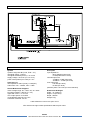
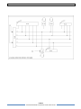
PS 680
SIX CHANNEL POWER SUPPLY
WITH AUX MATRIX
USER MANUAL
Issue 2010 © ASL Intercom BV
DESIGNED AND MANUFACTURED BY:
ASL INTERCOM B.V.
ZONNEBAAN 42
3542 EG UTRECHT
THE NETHERLANDS
PHONE: +31 (0)30 2411901
FAX: + 31 (0)30 2667373
E-MAIL: [email protected]
WEB: www.asl-inter.com
CONTENT OF THIS USER MANUAL
1.0
SAFETY INSTRUCTIONS ......................................................... 3
2.0
GENERAL DESCRIPTION PS 680 ........................................... 4
3.0
UNPACKING ............................................................................. 4
4.0
MECHANICAL INSTALLATION ................................................. 4
5.0
WARRANTY .............................................................................. 4
7.0
FRONT PANEL CONTROLS ..................................................... 5
8.0
REAR PANEL CONTROLS & CONNECTORS ......................... 6
9.0
PARTY LINE, TECHNICAL CONCEPT ..................................... 7
10.0
CABLING ................................................................................... 7
11.0
EARTHING CONCEPT .............................................................. 8
12.0
TECHNICAL SPECIFICATIONS PS 680 ................................... 8
13.0
SYSTEM CONFIGURATION ..................................................... 9
PAGE 2
User Manual PS 680 / Issue 2010 © ASL Intercom BV
1.0
SAFETY INSTRUCTIONS
Please always follow these instructions to help ensure against injury to yourself
and/or damage to the system
1. Read all safety and operating instructions
before you operate the apparatus.
2. Retain all safety and operating instructions
for future reference.
3. Heed all warnings on the apparatus and in
the safety and operating instructions and
follow all installation and use instructions.
4. Follow all installation, operating and use
instructions
5. Unplug the apparatus from the AC power
outlet before cleaning. Use only a damp cloth
for cleaning the exterior of the apparatus.
6. Do not use accessories or attachments not
recommended by the manufacturer, as they
may cause hazards and void the warranty.
7. Do not operate this apparatus in high
humidity areas or expose it to water or
moisture.
8. Do not place the apparatus on an unstable
cart, stand, tripod, bracket or table. The
apparatus may fall, causing serious personal
injury and damage to the apparatus.
9. Do not block or cover any openings in the
apparatus. These are provided for ventilation
and protection from overheating. Never place
the apparatus near any heat sources such as
radiators, heat registers, stoves, or other
apparatus (including amplifiers) that produce
heat. Do not place the apparatus in an
enclosure such as a cabinet without proper
ventilation.
10. Operate the apparatus using only the type of
power source indicated on the marking label.
Unplug the apparatus‟ power cord by
gripping the power plug, not the cord.
11. Insert the plug properly. Do not defeat the
safety purpose of the polarized or groundingtype plug. An American polarized AC line
plug has two blades with one wider than the
other. This plug will fit only one way into the
power outlet. This is a safety feature. If you
are unable to insert the plug fully into the
outlet, try reversing the plug. If the plug still
fails to fit, contact an electrician to replace
the obsolete outlet. A grounding type plug
has two blades and a third grounding prong.
The wide blade or the third prong are
provided for your safety. If the provided plug
does not fit into your outlet, consult an
electrician to replace the obsolete outlet.
12. Route power supply cords so that they are
not likely to be walked on or pinched by
items placed upon or against them. Pay
particular attention to cords at plugs,
convenience receptacles, and the point
where they exit from the apparatus.
13. Do not overload wall outlets or extension
cords, as this can result in a risk of fire or
electrical shock.
14. Unplug this apparatus during lightning storms
or when unused for long periods of time.
15. Never insert objects of any kind into the
apparatus through openings, as the objects
may touch dangerous voltage points or short
out parts. This could cause fire or electrical
shock.
16. Refer all servicing to qualified service
personnel. Servicing is required when the
apparatus has been damaged in any way,
such as when the power-supply cord or plug
is damaged, liquid has been spilled or
objects have fallen into the apparatus, the
apparatus has been exposed to rain or
moisture, does not operate normally, or has
been dropped.
PAGE 3
User Manual PS 680 / Issue 2010 © ASL Intercom BV
2.0
GENERAL DESCRIPTION PS 680
The PS 680 is designed to be a six channel power
supply in an ASL intercom system and can be used
in portable as well as fixed applications.
It incorporates two adjustable auxiliary signal inputs
and uses only 1U of 19” rack space. The unit is
ideal for use in applications where standard
microphone cable is available and ease of setup is
of paramount importance.
Inside the unit are 2 switch mode power supply
modules, which are fully protected and can together
drive at least 20 Pro Series beltpacks or 10 Pro
Series speaker stations (or a combination)
operating at full power.
The Auxiliary Matrix:
On the rear panel of the PS 680 are 2 inputs for
external audio signals, so-called „auxiliary‟ or „AUX‟
signals. Each AUX signal may be injected to each
of the 6 intercom channels, with for each channel a
volume control for each AUX signal. With master
volume control knobs on the front panel the overall
level of each AUX signal to the intercom channels
may be adjusted. Each AUX input may be switched
to either line or mic level. When mic level is
3.0
If any are missing, contact your dealer.
ASL has taken great care to ensure that this
product reaches you in flawless condition.
After unpacking the unit please inspect for any
physical damage to the unit, and retain the shipping
carton and relevant packing materials for use
should the unit need returning.
If any damage has occurred, please notify your
dealer immediately so that a written claim can be
initiated.
Please also refer to the warranty section of this
manual.
MECHANICAL INSTALLATION
A vertical rack space of 1U (1.75”/ 44,5 mm) is
required for the PS 680. It is not necessary to
provide rear support by extra bracing or shelving.
Adequate ventilation must be provided by allowing
sufficient space around the sides and rear of the
unit to ensure free circulation of air.
5.0
Remote Mute Control:
The Mic Mute and Buzzer Mute push buttons on the
front panel of the PS 680 allow for sending these
mute signals to all channels simultaneously. In case
it is required that these signals can also be sent to
each channel separately, an external switch box is
needed which can be connected to a D-25
connector on the rear panel.
UNPACKING
The shipping carton contains the parts listed below:
The PS 680
Mains power cable
Spare fuses
4.0
selected, +30V phantom power is available at the
referring AUX input connector.
Fully electronic switching increases reliability and
allows for a Mic Mute and Buzzer Mute function:
By pushing the “All Mics Off‟ button on the
front panel the microphones of the stations
connected to the PS 680 are muted. At
each user station the microphone may be
switched again by pushing a TALK button.
By pushing the „All buzzers Off‟ button on
the front panel all buzzers of the stations
connected to the PS 680 are muted. To
abolish the „all buzzers off‟ status of all
these stations, this button has to be pushed
again.
Forced cooling is not required.
The power supply regulator is mounted on the rear
of the unit. After a period of time it will feel hot to the
touch. This is quite normal, and should be no cause
for alarm.
WARRANTY
This unit is warranted by ASL Intercom to the
original end-user purchaser against defects in
workmanship and materials in its manufacture for a
period of one year from the date of shipment to the
end-user.
Faults arising from misuse, unauthorized
modifications or accidents are not covered by this
warranty. If the unit is faulty, it should be sent in its
original packing to the supplier or your local ASL
dealer, with shipping prepaid. A note must be
included stating the faults found and a copy of the
original suppliers invoice.
PAGE 4
User Manual PS 680 / Issue 2010 © ASL Intercom BV
6.0
MAINS POWER
WARNING: This appliance must be earthed
The PS 680 may be connected to a mains power
outlet of 100 - 240 Volts, 50 – 60 Hz, 150 watts.
The outlet should have a clean earth. Avoid using
mains outlets which also power dimmer controlled
lighting equipment.
Fuse type for all voltages: T 1250
The wires in the mains lead are color coded in
accordance with the following code:
Green-and-yellow:
Earth / safety ground
Blue:
Neutral
Brown:
Live
In case the colors of the wires in the mains lead do
not correspond with the colored markings
identifying the terminals in your plug, proceed as
follows:
The wire which is colored green-and-yellow
must be connected to the terminal in the
plug which is marked with the letter „E‟, or
by the earth symbol or colored green.
The wire which is colored blue must be
connected to the terminal which is marked
with the letter „N‟ or colored black.
7.0
The wire which is colored brown must be
connected to the terminal which is marked
with the letter „L‟ or colored red.
Safety Earth
The green-and-yellow wire of the mains cord must
always be connected to the electrical installation
safety earth or ground. It is essential for personal
safety as well as for proper operation of the PS 680
and the connected user stations. This wire is
internally connected to all exposed metal surfaces
of the PS 680. Any rack framework into which this
unit is mounted should be connected to the same
grounding circuit.
Powering Up Procedure
Make sure that the red power switch on the
left side of the front panel is OFF.
Connect the power cord to the rear of the
station.
Plug the other end of the power cord into a
properly grounded mains outlet.
Turn on the power with the red button.
The red overload LED lights up for about 3
seconds and then extinguishes. Now the
green power LED is lit, indicating the PS
680 is active
FRONT PANEL CONTROLS
1
POWER ON/OFF switch
Mains power push button for switching ON and OFF
the internal power supplies
3
POWER LED
This LED illuminates if line power is supplied by the
internal power supply
2
OVERLOAD LEDs
There is an overload LED for channel A, C and E
(powered by PSU 1) and an overload LED for
channel B, D and F (powered by PSU 2).
An overload LED illuminates if a circuit breaker has
shut off the 30V DC line power due to overload.
A cause for overload can be too many user stations
connected or a short-circuit in the interconnecting
cables. The circuit breaker resets automatically 3
seconds after the cause of the overload has been
removed, restoring the line power. During shortcircuit the overload LED flashes every 3 seconds.
Every time mains power is switched on the LED is
lit for a few seconds.
4
ALL MICS ON/OFF button
With this push button all microphones of the
connected stations can be muted
5
ALL BUZZERS ON/OFF button
With this push button all buzzers of the connected
stations can be muted
6
AUX MASTER VOLUME control knobs
These knobs adjust the level of each aux input
signal to the intercom lines
7
AUX MATRIX trimmers
These trimmers control the volume of each AUX
input signal as sent to each channel A - F
PAGE 5
User Manual PS 680 / Issue 2010 © ASL Intercom BV
8.0
REAR PANEL CONTROLS & CONNECTORS
8
LINE connectors A - F
These XLR-3 connectors are for connecting the 8
intercom party lines (standard microphone cable)
Pin assignments :
pin 1: 0V / ground shield
pin 2: +30V power wire
pin 3: audio wire
To activate a mic of buzzer mute, the switch box
connects the required pins of the D-25 connector to
ground. See D-25 pin layout below.
9
AUX INPUT connectors
These two XLR-3 Aux inputs are electronically
balanced and accept audio levels between –18dBu
to +22dBu on line level and –38dBu to +2dBu on
mic level.
Pin assignments :
pin 1: 0V / ground
pin 2: signal +
pin 3: signal 10
MIC / LINE switches
With these switches Line level or Mic level for each
AUX input can be selected. When mic level is
selected, a +30V DC phantom power is supplied to
pins 2 and 3 of the AUX input connector.
11
MIC GAIN trimmers
These trimmers adjust the sensitivity of the AUX
input when mic level is selected.
12
FUSE holder
The fuse protects the PS 680 against severe internal
damage, in case of malfunction of the internal power
supplies.
Before replacing the fuse the mains cord must
be removed. The fuse has to be T 1250 mA for
all mains voltages 100 – 240V AC.
13
MAINS inlet
IEC Mains connector. For correct wiring see section
6.0.
14
Using this switch box Mic or Buzzer mute signals
can be sent to all channels simultaneously OR to
each channel separately.
REMOTE MUTE CONTROL + AUX
OUTPUTS connector
The Mic Mute and Buzzer Mute push buttons on the
front panel of the PS 680 allow for sending these
mute signals to all channels simultaneously.
In case it is required that these mute signals can
also be sent to each channel separately, an external
switch box is needed which may be connected to
this D25 connector.
The external switch box is made to order. Specific
requirements of the user as far as for instance type
of switches can be fulfilled.
On the D-25 connector are also available the
unbalanced AUX signals, on pin 2 and 3. It concerns
the pre-amplified signals taken after the AUX master
volume controls (#6) before they are sent to the Aux
matrix. Use high impedance loads only (minimum
20 kΩ); lower loads may disrupt the AUX signals to
the intercom lines.
Pin layout of the D-25 connector:
1
2
3
4
5
6
7
8
9
10
11
12
13
14
15
16
17
18
19
20
21
22
23
24
25
Ground (0V)
Unbalanced AUX signal 2
Unbalanced AUX signal 1
+30V DC (max. load 1A )
+30V DC (max. load 1A)
+9V DC (max. load 50 mA )
Mic mute all channels
Mic mute channel F
Mic mute channel E
Mic mute channel D
Mic mute channel C
Mic mute channel B
Mic mute channel A
Ground (0V)
Ground (0V)
Ground (0V)
not used
not used
Buzzer mute all channels
Buzzer mute channel A
Buzzer mute channel B
Buzzer mute channel C
Buzzer mute channel D
Buzzer mute channel E
Buzzer mute channel F
Please note that the +9V DC supply is NOT
short-circuit protected !
PAGE 6
User Manual PS 680 / Issue 2010 © ASL Intercom BV
9.0
PARTY LINE, TECHNICAL CONCEPT
User stations in an ASL intercom system are
connected via one or several 'party lines'. A party
line offers two way („full duplex‟) communication and
consists of standard microphone (multi-pair) cable.
One wire is used as an audio line, one as a power
line and the screen of the cable functions as
earth/return.
Current drive is used for signal transfer. Each station
utilizes a current amplifier to amplify the microphone
signal and place it on the common audio line where,
due to the constant line impedance (situated in the
power supply between XLR pin 3 and 1), a signal
voltage is developed which can be further amplified
and sent to the headphones or loudspeakers.
10.0
This principle has three advantages:
the use of a single audio line allows several
stations to talk and listen simultaneously
due to the high bridging impedance offered
by each station, the number of stations on
the party line has no influence on the level
of the communications signal
power and audio to the intercom stations
use the same cable
The Call signal is also sent as a current on the audio
line. It develops a DC potential over the line
impedance which will be sensed by each station and
interpreted as a Call signal.
CABLING
The intercom line connectors are of the XLR-3 type. Audio and Call signals are on pin 3, DC power is on pin 2
and pin 1 is connected to the shield of the cable which functions as the common return for audio and power.
The audio signal is transferred in an unbalanced way (see „Party Line, Technical Concept‟).
To avoid earth loops (hum), the possible effect of electromagnetic fields and to minimize power loss, certain rules
have to be obeyed when installing the cabling of an intercom system :
Use high quality cable
Use high quality microphone cable (shielded two
conductor cable, minimum 2x 0.30 mm2).
In case multi-pair microphone cable is used, it
should be of high quality and each pair should
consist of two conductors (minimum 2x 0.15 mm2)
with separate shield and an overall shield.
Keep cables parallel as much as possible
When two (multi channel) units in a network are
connected by more than one cable, make sure that
these cables are parallel to each other over the
whole distance between those units. When using
multi-pair cable, parallelism is ensured in the best
possible way.
Use flexible cable
Use flexible single and multi-pair microphone cable
instead of cable with solid cores, especially when
the cable is subjected to bending during operation or
installation.
Avoid closed loops
Always avoid that intercom cables are making a
closed loop. So-called 'ring intercom' should not
physically be cabled as a ring..
Cable screens to XLR pin 1
The screen of each separate microphone cable
and/or the screen of each single pair in a multi-pair
cable, should be connected to pin 1 of each XLR-3
connector. Do not connect these screens to the
metal housing of ASL unitst or XLR-3 wall boxes.
See section „Earthing Concept‟.
Connect metal cable trunks, wall boxes and
overall multi-pair cable screens to clean earth
Metal cable trunks, metal wall boxes and overall
multi-pair cable screens should be interconnected
and, at the 'central earth point' in the intercom
network only, be connected to a clean earth or a
safety earth. (see section „Earthing Concept‟).
Keep metal connection boxes and cable trunks
or pipes isolated from other metal parts
Metal trunks or pipes for intercom cables and metal
connection boxes should be mounted in such a way
that they are isolated from any other metal housing
or construction part.
Keep cables away from electromagnetic sources
Keep intercom cables away from high energy
cables, e.g. 115/230/400V mains power or dimmer
controlled feeds for spotlights. Intercom cables
should cross high energy cables at an angle of 90º
only. Intercom cables should never be in the same
trunks as energy cables.
Place power supply in a central position
In case of a system powered by a separate power
supply: In order to diminish power losses, place the
power supply as close as possible to where most
power consumption occurs, in other words most
user stations are placed.
ASL powered units to a 'clean' mains outlet
Master stations or power supplies should be
connected to a mains outlet with a clean earth.
Other audio equipment may be connected to this
mains outlet, but avoid using an outlet which also
powers dimmer controlled lighting systems.
In case of more complex installations, don't hesitate
to contact us for advice.
PAGE 7
User Manual PS 680 / Issue 2010 © ASL Intercom BV
11.0
EARTHING CONCEPT
12.0
TECHNICAL SPECIFICATIONS PS 680
System
dynamic range: 80 dB (1 kHz, THD < 1%)
call signal (send): +2.8 mA
call signal threshold (receive): +2.4V DC
supply voltage: +30 V DC (12 V to 32 V)
power interrupt time (mic mute): 0.1 sec
Intercom Line
line impedance: 350 Ω (1kHz), 2.2 kΩ (DC)
audio level: nom. –18 dBu, max. +4 dBu
Switch Mode Power Supplies
mains voltage range: 90 – 240 V AC, 50 - 60Hz
DC output voltage: +30V DC (+/- 5%)
ripple and noise: < 11 mV rms
max. output power: 2x 45 watt
circuit-breaker delay time: 0.2 sec.
automatic reset time: 3.0 sec.
Aux Inputs
Input impedance:
30 kΩ (balanced line level)
4.6 kΩ (balanced mic level)
nominal input level:
-18 dBu to +6 dBu (line level)
-38 dBu to –14 dBu (mic level)
max. input level:
+22 dBu (line level)
+2 dBu (mic level)
phantom power +30 V DC (mic level selected)
Dimensions & Weight
Width: 19" (483mm)
Height: 1U (44.5mm)
Depth: 250mm
Weight: 2 Kg
0 dBu defined as 775 mV into open circuit
ASL reserves the right to alter specifications without prior notice
PAGE 8
User Manual PS 680 / Issue 2010 © ASL Intercom BV
13.0
SYSTEM CONFIGURATION
PAGE 9
User Manual PS 680 / Issue 2010 © ASL Intercom BV


![User Manual PS 260 [ASL]](http://vs1.manualzilla.com/store/data/005875222_1-79f7ffd37f8e6cc3732f57605cc0b82b-150x150.png)
![User Manual PS 260 [ASL]](http://vs1.manualzilla.com/store/data/006916739_1-983cb380987130e2fe2cf762515f3398-150x150.png)
![User Manual PS 430 [ASL]](http://vs1.manualzilla.com/store/data/005978378_1-af53a31d0469f4c1b9fb526270e34a3a-150x150.png)
![User Manual PS 260 [ASL]](http://vs1.manualzilla.com/store/data/005985662_1-3f2d644a9ec4c6b19392498f7dfdae07-150x150.png)
![User Manual BS 15 [ASL]](http://vs1.manualzilla.com/store/data/005996459_1-9378f5a1cc1ed113f3d71e1dad6bbd12-150x150.png)
![User Manual PS 260 [ASL]](http://vs1.manualzilla.com/store/data/005945478_1-a7dc8230481a9f04873ba664e1b890b7-150x150.png)
![User Manual PS 260 [ASL]](http://vs1.manualzilla.com/store/data/005887031_1-132c7eb8ac96774a27528798f7f3ad09-150x150.png)