1
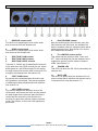
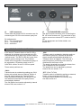
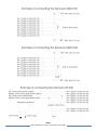
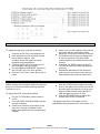
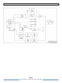
PS 155
INTERFACE TO SIMPLEX („PUSH TO TALK‟)
WIRELESS INTERCOM
USER MANUAL
Issue 2011 © ASL Intercom BV
DESIGNED AND MANUFACTURED BY:
ASL INTERCOM BV
ZONNEBAAN 42
3542 EG UTRECHT
THE NETHERLANDS
PHONE: +31 (0)30 2411901
FAX: +31 (0)30 2667373
E-MAIL: [email protected]
WEB: www.asl-inter.com
CONTENT OF THIS USER MANUAL
1.0
2.0
3.0
5.0
6.0
7.0
8.0
9.0
10.0
11.0
12.0
13.0
14.0
15.0
GENERAL DESCRIPTION ............................... 3
UNPACKING ......................................... 3
WARRANTY .......................................... 3
FRONT PANEL CONTROLS .............................. 4
REAR PANEL CONNECTORS ............................ 5
RECEIVE AND TRANSMIT MODE ......................... 5
THE CABLE TO THE WIRELESS UNIT ...................... 6
SIDE TONE ADJUSTMENT PROCEDURE (PARTY LINE) ........ 8
VOX ADJUSTMENT PROCEDURE ......................... 8
INTERNAL CONTROLS ................................. 9
TECHNICAL SPECIFICATIONS ........................... 9
PROBLEM SOLVING .................................. 10
POSSIBLE SYSTEM CONFIGURATIONS ................... 11
BLOCK DIAGRAM PS 155 .............................. 12
PAGE 2
User manual PS 155 / Issue 2011 © ASL Intercom BV
.
1.0
GENERAL DESCRIPTION
The PS 155 is designed to be a single channel
audio interface between simplex („push to talk‟)
wireless intercom systems and ASL wired (party
line) intercom systems.
The unit is housed in a strong steel tabletop case.
Located on the front panel are volume controls
(send and receive), side tone adjustment
trimmers, a test tone switch, VOX adjustment
trimmers and TX controls.
The PS 155 contains an audio interface which
splits the audio on the wired intercom party line
into an audio output and an audio input. Via the
audio output the audio of the party line is sent to
the wireless intercom system. Via the audio input
the audio of the wireless system is sent to the
party line. Audio output and audio input can be
separately volume controlled by a SEND
respectively a RECEIVE volume knob. Both the
output and the input are transformer balanced.
2.0
ASL has taken great care to ensure this product
reaches you in flawless condition.
If the internal Transmit Switch of the PS 155 is
triggered, the wireless unit goes from „receive
mode‟ to „transmit mode‟.
There are 3 ways to trigger the Transmit Switch,
to be selected by a 3-position switch in the TX
CONTROL section of the PS 155 front panel. See
section 7.0.
After unpacking the unit please inspect for any
physical damage to the unit, and retain the
shipping carton and relevant packing materials for
use should the unit need returning.
If any damage has occurred, please notify your
dealer immediately so that a written claim can be
initiated. Please also refer to the warranty section
of this manual.
WARRANTY
This unit is warranted by ASL Intercom to the
original end-user purchaser against defects in
workmanship and materials in its manufacture for
a period of one year from date of shipment to the
end-user.
4.0
To connect the PS 155 to a wireless intercom
system, a special cable is needed. In this user
manual it is assumed that the cable is connected
to a simplex („push to talk‟) wireless intercom
station (Motorola, Kenwood or other make),
hereinafter called “the wireless unit”.
UNPACKING
The shipping carton contains the parts listed
below:
the PS 155
this user manual
a Sub-D 9 connector (cable part)
If any are missing, contact your dealer.
3.0
The built-in test tone generator assists obtaining
the best possible side tone rejection in the audio
interface section. The tone generator is activated
by pushing the recessed switch at the front panel.
Faults arising from misuse, unauthorized
modifications or accidents are not covered by this
warranty. If the unit is faulty it should be sent in its
original packing, to the supplier or your local ASL
dealer, with shipping prepaid. A note must be
included stating the faults found and a copy of the
original suppliers invoice.
INSTALLATION
This PS 155 is powered (30V DC) by an ASL
master station or separate power supply, via the
intercom connection cable (the party line).
Connect this cable to the LINE connector on the
rear panel. Use professional microphone cable
with 2 wires and 1 shield only.
The PS 155 is fully protected against wiring
mistakes (reverse power) or short-circuit in the
intercom connecting cable.
To connect the PS 155 to the wireless unit a
special cable is needed, to be connected to the
Sub-D9 connector on the rear panel. For the pin
configuration of this connector and further details,
see section 8.0.
PAGE 3
User manual PS 155 / Issue 2011 © ASL Intercom BV
.
5.0
FRONT PANEL CONTROLS
1
RECEIVE volume knob
This knob is for adjusting the level of the audio
that is received from the wireless unit
2
SEND volume knob
This knob is for adjusting the level of the audio
that is sent to the wireless unit
3
4
5
SIDE TONE LOW trimmer
SIDE TONE HIGH trimmer
SIDE TONE LEVEL trimmer
Trimmers 3, 4 and 5 are for adjusting the rejection
of the side tone; the LEVEL trimmer for the whole
audio spectrum, the HIGH trimmer for fine tuning
the high frequencies and the LOW trimmer for fine
tuning the low frequencies. See section 9.0
6
TEST TONE button
By pushing this recessed button the built-in test
tone generator is activated. The test tone assists
in obtaining the best possible side tone rejection.
See section 9.0
8
VOX RELEASE trimmer
After the audio signal of the intercom party line
falls below the set VOX level, the wireless unit
stays in transmit mode for a period of time that is
preset by this trimmer. See section 10.0 for the
VOX adjustment procedure.
9
TX CONTROL select switch
This switch has the positions VOX, CALL and
PTT, each indicating the way the wireless unit is
triggered to go from receive mode to transmit
mode. See section 7.0
10
POWER LED
This LED is lit when the PS 155 is powered by the
intercom line.
11
Rx/Tx LED
This LED is lit green when the wireless unit is in
receive mode and lit red when the wireless unit is
in transmit mode. See also section 7.0.
7
VOX LEVEL trimmer
This trimmer adjusts the detection level of the
VOX switch. As soon as the VOX circuitry detects
an audio signal on the intercom party line that is
louder than the level set by this trimmer, the
wireless unit goes from receive mode to transmit
mode. See section 10.0 for the VOX adjustment
procedure.
PAGE 4
User manual PS 155 / Issue 2011 © ASL Intercom BV
.
6.0
REAR PANEL CONNECTORS
12
LINE connectors
These male and female XLR-3 connectors are for
connecting the PS 155 to the intercom party line.
Pin assignments:
Pin 1: 0 V / ground shield
Pin 2: +30 V power wire
Pin 3: audio wire
7.0
13
TO TRANSCEIVER connector
This Sub-D 9 pole connector is for connecting the
PS 155 to the wireless unit. The connector is also
used to connect an external PTT switch to the PS
155.
For pin assignment and further details, see
section 8.0.
RECEIVE AND TRANSMIT MODE
If the internal Transmit Switch of the PS 155 is
triggered, the wireless unit connected to the PS
155 (see section 8.0) goes from „receive mode‟ to
„transmit mode‟. The Rx/Tx LED (#11) goes from
being lit green to being lit red. The Transmit
Switch can be triggered in three different ways, to
be selected by a 3-position switch in the TX
CONTROL section of the PS 155 front panel.
These switch positions are:
„CALL‟
Transmit mode is enabled by pushing any CALL
button at the wired intercom stations. Detect of
this Call signal triggers the Transmit Switch.
When this option is selected, the buzzers of all
user stations connected to the party line are
automatically disabled.
The Call Detect level can be adjusted by internal
trimmer R29, see section 11.0.
„VOX‟
Transmit mode is enabled by detecting audio on
the intercom party line. As soon as this audio
signal exceeds an adjustable threshold, the
Transmit Switch is triggered. The VOX has a
special frequency contouring circuit which is
optimized for the human voice.
The attack (threshold) level and the release time
can be adjusted at the front panel.
The attack time can be adjusted by internal
trimmer R9, see section 11.0.
„PTT‟ (Push To Talk)
Transmit mode is enabled by pushing an external
button, to be connected to the PS 155.
This push button should be momentary only.
See also section 8.0
PAGE 5
User manual PS 155 / Issue 2011 © ASL Intercom BV
.
8.0
THE CABLE TO THE WIRELESS UNIT
This section describes the connection between
the PS 155 and the wireless unit and the
connection between the PS 155 and an external
PTT switch.
At the wireless unit the connection cable is
plugged into the connector which is normally
used to connect a speaker/microphone device.
At the PS 155 the cable is plugged into Sub-D9
connector at the rear panel.
Pin assignment of the Sub-D9 connector:
Pin 1: Audio input Pin 2: Audio input +
Pin 3: PTT button switch
Pin 4: Transmit switch (Common)
Pin 5: Transmit switch (Normally Open)
Pin 6: Transmit switch (Normally Closed)
Pin 7: Ground/shield
Pin 8: Audio output +
Pin 9: Audio output Pin 1 and 2 :
The Audio Input is transformer balanced,
decoupled with capacitors to obtain a high DC
resistance. If the wireless unit uses asymmetric
signal transport then the audio input - (pin 1) is to
be connected to the ground of the wireless unit
and (if necessary) to pin 7 of the Sub-D 9
connector.
Pin 8 and 9 :
The Audio Output is transformer balanced,
decoupled with capacitors to obtain a high DC
resistance. If the wireless unit uses asymmetric
signal transport then the output - (pin 9) is to be
connected to the ground of the wireless unit and
(if necessary) to pin 7 of the Sub-D9 connector.
The gain of the Audio Output can be adjusted by
internal trimmer R4, see section 11.0.
Pin 3 and 7 :
An external PTT (Push To Talk) button may be
connected to these pins of the Sub-D9 connector.
By pushing the PTT button the wireless unit is
triggered to go from receive mode to transmit
mode. De PTT button only works if the TX
CONTROL select switch (#9) is set in position
“PTT:”
Pins 4, 5 and 6 :
The Transmit Switch contacts are located
between these pins of the sub-D9 connector.
Normally Open:
Most wireless units need a contact to be
closed to go from receive mode to
transmit mode. Use pin 4 and 5. Some
wireless units need to see a special DC
resistance. Ask the manufacturer of the
wireless intercom system to advise you on
what value of the resistor to use. Usually
the resistor is to be mounted in the
Common wire of the Transmit Switch
contacts. See also drawings below.
Normally Closed:
Some wireless units need a contact to be
opened to go from receive to transmit
mode. Use pin 4 and 6.
Important notices:
Use high quality cables and connectors
Make sure that all interconnecting cables
are properly shielded. This to avoid RF
interference of the wireless intercom system
and the wired ASL intercom system
If possible, use a balanced audio
connection to and from the wireless unit.
Using a cable assembly from the wireless
intercom manufacturer is to be preferred.
Make sure that the connections made to the
wireless unit are according to the
specifications of its manufacturer
Always use the by ASL supplied Sub-D9
connector cable part; this connector is
shielded
To avoid RF interference, place the wireless
unit not to close to the PS 155 and the
intercom cables. But the connection cable
should not be too long.
PAGE 6
User manual PS 155 / Issue 2011 © ASL Intercom BV
.
PAGE 7
User manual PS 155 / Issue 2011 © ASL Intercom BV
.
9.0
SIDE TONE ADJUSTMENT PROCEDURE (PARTY LINE)
To adjust the side tone, proceed as follows:
Connect the PS 155 to the wireless unit
If the wireless unit has a volume control
turn it down to approx. 10%;
a volume that is too high may cause
problems such as distortion
Connect the PS 155 to the party line of
the wired ASL intercom system
Put the SEND and RECEIVE volumes of
the PS 155 in the 12 o‟clock position
Push the „Test Tone‟ button with a pen or
pencil
10.0
Listen to one of the wireless units (not the
one which has the connection cable)
Adjust the 3 side tone trimmers so that at
the wireless unit the test tone listen level
is set to a minimum. First the LEVEL
trimmer and then the HIGH and the LOW
trimmer.
If needed, the SEND volume of the PS
155 can be turned up while adjusting the
trimmers
Repeat the adjustment of the trimmers
over and over until you are sure that you
have obtained the minimum listen level
VOX ADJUSTMENT PROCEDURE
Before starting this procedure make sure that the
party line side tone has been properly adjusted
(see section 9.0) !
To adjust the VOX, proceed as follows:
Put the TX CONTROL select switch to
“VOX”
Turn the LEVEL and RELEASE trimmers
counter clockwise
Connect an intercom user station to the
party line, connect a headset to that
station and speak into the microphone of
headset
With the LEVEL trimmer adjust the audio
level on the party line to which the PS 155
should trigger the wireless unit to go from
receive mode to send mode (the Rx/Tx
LED changes from green to red)
With the RELEASE trimmer adjust the
release time of the VOX switch
The attack time of the VOX switch can be
adjusted by internal trimmer R9, see section 11.0.
PAGE 8
User manual PS 155 / Issue 2011 © ASL Intercom BV
.
11.0
INTERNAL CONTROLS
To access the internal trimmers the PS 155 needs to be opened. Before doing so, disconnect the unit of all
other equipment. Open the PS 155 by removing the two screws of the cover at either side. Then connect
the PS 155 to the intercom party line and to the wireless unit.
OUTPUT GAIN trimmer (R4)
With this trimmer the output gain can be adjusted.
The trimmer is located on the PCB board at the
left, near to the transformers.
To increase the gain, turn clockwise.
To decrease the gain, turn counter clockwise.
VOX DETECT trimmer (R9)
With this trimmer the attack time of the VOX
switch can be adjusted. Proceed as follows:
Set the TX CONTROL select switch to
position “VOX”
Connect a user station to the intercom
party line and connect a headset to that
station
Speak into the headset microphone
First adjust the LEVEL and RELEASE
trimmers at the front panel
Then adjust the attack time with trimmer
R9
12.0
CALL DETECT trimmer (R29)
With this trimmer the CALL detect level can be
adjusted. Proceed as follows:
Set the TX CONTROL select switch at the
front panel in the position CALL
Connect a user station to the intercom
party line
Press and hold a CALL button on that user
station
Turn trimmer R29. If the trimmer is turned
too much counter clockwise the internal
Transmit Switch is triggered every second
(this is also shown by the Rx/Tx LED). If
the trimmer is turned too much clockwise
the internal Transmit Switch has a very
long release time when the CALL button of
the connected station is released. Try to
find a suitable position for the trimmer in
between those two points.
TECHNICAL SPECIFICATIONS
Side Tone (party line)
Rejection : 0 – 35 dB adjustable
Dimensions & Weight
Width: 90 mm / Height: 38 mm
Depth: 124 mm / Weight: 260 grams
PAGE 9
User manual PS 155 / Issue 2011 © ASL Intercom BV
.
13.0
PROBLEM SOLVING
PROBLEM
CAUSE
CHECK
PS 155 does not respond
No power supply or defective
cable of the wired intercom
Wired intercom power supply and party
line cable
No audio of the wireless
system to the party line
„Receive‟ volume is too low
„Receive‟ volume knob
Cable not properly connected
Cable to the wireless unit
PS 155 not (properly) connected
Cable to the wired intercom
„Send‟ volume too low
„Send‟ volume knob
Volume on wireless unit too low
Volume knob of the wireless unit
Cable to wireless unit not properly
connected
Cable to the wireless unit
PS 155 not (properly) connected
TX Control not in the position PTT
Cable to the wired intercom
Change the TX Control switch to PTT
Connection of the external switch
not properly done
Connection of the external PTT switch
Connection between wireless unit
and PS 155 incorrect.
TX Control switch not in the
position VOX
The cable and the details of both units..
VOX level too low
Turn the VOX level trimmer clockwise
Audio level on the wired intercom
line too low
Increase the audio level on the wired
intercom by speaking louder and closer
into the microphone.
Turn the VOX trimmer counter
clockwise
No audio from the party
line to the wireless system
Wireless unit does not
respond to the external
PTT switch
Units do not respond to
VOX
In VOX mode the units
stays in transmit mode
In VOX mode the signal is
briefly interrupted
After reception of audio
from the wireless unit the
PS 155 switches to
transmit briefly
The audio on the party line
changes when the PS 155
changes transmit and
receive mode
(interference/distortion).
VOX level too sensitive
Put the TX Control switch in the
position VOX
Bad side tone rejection
Re-adjust the side tone trimmers again
Level of the wireless unit is too
high
VOX level not sensitive enough
Turn the volume control of the wireless
unit down.
Turn the VOX LEVEL trimmer clockwise
Release time too short
Bad side tone rejection
Turn the VOX RELEASE trimmer
clockwise.
Re-adjust the side tone trimmers again.
Input signal is too high
Turn down the „Receive‟ level
Input signal is too high
Turn down the volume of the wireless
unit.
Turn down one or both levels
Send and/or Receive volume too
high
Improperly connected cable.
Check cables and connections.
Bad sidetone rejection
Re-adjust the side tone trimmers again
PAGE 10
User manual PS 155 / Issue 2011 © ASL Intercom BV
.
14.0
POSSIBLE SYSTEM CONFIGURATIONS
A
B
A
B
PAGE 11
User manual PS 155 / Issue 2011 © ASL Intercom BV
.
15.0
BLOCK DIAGRAM PS 155
PAGE 12
User manual PS 155 / Issue 2011 © ASL Intercom BV
.

![User Manual PS 430 [ASL]](http://vs1.manualzilla.com/store/data/005978378_1-af53a31d0469f4c1b9fb526270e34a3a-150x150.png)

![User Manual PS 150 [ASL]](http://vs1.manualzilla.com/store/data/005768686_1-8816d5b7fb10913376d12c46f49c4ab8-150x150.png)

![User Manual PS 260 [ASL]](http://vs1.manualzilla.com/store/data/005875222_1-79f7ffd37f8e6cc3732f57605cc0b82b-150x150.png)
![User Manual PS 260 [ASL]](http://vs1.manualzilla.com/store/data/005887031_1-132c7eb8ac96774a27528798f7f3ad09-150x150.png)