1
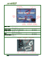
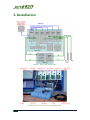
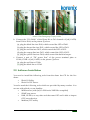
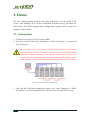
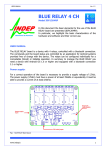
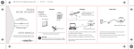
JetI/O 6500 Demo Box
User Manual
First Edition, June 2008
Korenix Technology Co., Ltd
www.korenix.com
Tel: +886-2-8219-3000
Fax:+886-2-8219-3300
Copyright Notice
Copyright© 2008 Korenix Technology Co., Ltd.
All rights reserved.
Reproduction without permission is prohibited.
Information provided in this manual is intended to be accurate and reliable.
However, the original manufacturer assumes no responsibility for its use, or
for any infringements upon the rights of third parties that may result from its
use.
The material in this document is for product information only and is subject
to change without notice. While reasonable efforts have been made in the
preparation of this document to assure its accuracy, Korenix assumes no
liabilities resulting from errors or omissions in this document, or from the use
of the information contained herein.
Korenix reserves the right to make changes in the product design without
notice to its users.
Acknowledgments
Korenix is a registered trademark of Korenix Technology Co., Ltd.
All other trademarks or registered marks in the manual belong to their
respective manufacturers.
2
www.korenix.com
Table of Contents
1.
2.
OVERVIEW ..................................................................................................................................4
1.1.
STANDARD PACKAGE LIST .....................................................................................................4
1.2.
OPTION...................................................................................................................................9
INSTALLATION ........................................................................................................................10
2.1.
2.1.1.
Setup The Demo Plate..................................................................................................... 11
2.1.2.
JetI/O 6510 Wiring ......................................................................................................... 11
2.1.3.
JetI/O 6511 Wiring.......................................................................................................... 11
2.1.4.
JetI/O 6512 Wiring .........................................................................................................12
2.1.5.
JetI/O 6520 Wiring .........................................................................................................12
2.1.6.
JetI/O 6550 Wiring .........................................................................................................12
2.2.
3.
4.
HARDWARE INSTALLATION ................................................................................................... 11
SOFTWARE INSTALLATION ....................................................................................................13
DEMO ..........................................................................................................................................14
3.1.
GETTING START....................................................................................................................14
3.2.
BASIC FUNCTION DEMONSTRATION .....................................................................................15
3.2.1.
JetI/O 6510 .....................................................................................................................15
3.2.2.
JetI/O 6511, JetI/O 6512.................................................................................................16
3.2.3.
JetI/O 6520 .....................................................................................................................16
3.2.4.
JetI/O 6550 .....................................................................................................................16
3.3.
SNMP MANAGEMENT AND ACTIVE ALARM .........................................................................17
3.4.
JETI/O 6550 LOGIC RULES ...................................................................................................18
3.5.
JETI/O 6550 PEER-TO-PEER I/O ...........................................................................................18
3.6.
OPC SERVER DEMONSTRATION............................................................................................20
3.7.
MODBUS/TCP DEMONSTRATION ..........................................................................................21
FURTHER SUPPORT................................................................................................................ 22
[email protected]
3
1. Overview
JetI/O 6500 Demo Box is designed to demonstrate JetI/O 6500 series products.
It is compact, portable. It presents the best results for customers, and
impresses them with product introduction as well as live demonstration.
1.1. Standard Package List
The JetI/O 6500 Demo Box includes the following items:
Item Name
Description
Q’ty
Demo Box
Portable demo box
1
JetI/O 6510
Intelligent I/O Server
8-CH Analog Input
1
JetI/O 6511
Intelligent I/O Server
8-CH Thermocouple Input
1
JetI/O 6512
Intelligent I/O Server
4-CH RTD Input
1
4
www.korenix.com
Picture
JetI/O 6520
Intelligent I/O Server
4-CH Analog Output
1
JetI/O 6550
Intelligent I/O Server
14-CH DI + 8-CH DO
1
JetNet 4008
Plug and play Ethernet switch
to connect JetI/O devices and
your PC/NB together
1
DR-4524
24VDC power module
1
Demo kit
y
y
y
y
y
y
y
1
DO LED x 4
DI LED x 6
Switch for DI x 6
Voltage meter x1
Knob for AI x1
24V DC terminal
A built-in Beeper
[email protected]
5
y 5 Wiring Cables:
1. DI Cable
(0) Black
(1) Brown
(2) Red
(3) Orange
(4) Yellow
(5) Green
2. DO Cable
(0) Black
(1) Brown
(2) Red
(3) Orange
(4) Yellow
3. AI Cable
(+)Red
(-)Orange
4. AO Cable
(+)Black
(-)Brown
6
www.korenix.com
5. PWR Cable
(+)Red
(-)Black
Thermocouple
Temperature detection with
JetI/O 6511
1
RTD
Temperature detection with
JetI/O 6512
1
Demo Plate
y Din-Rail x 2
y AC power input socket and
switch(110 to 240V AC)
y AC to DR-4524 (black, red,
green): to deliver power
from the AC power input to
the DR-4524
y DC from DR-4524 (black,
red): to transfer DC power
from DR-4524 to the power
terminal plate
y Power Terminal plate: DC
power terminal for JetI/O
and JetNet devices.
1
(see below)
[email protected]
7
Power Cords
USA plug x1
Euro plug x1
2
(See below)
Acrylic Stand
To sustain the demo plate
2
(See below)
Sensor Holders
One pair for Thermocouple
One pair for RTD
4
(See below)
Keys
Keys for the demo box
2
(See below)
6
(See below)
Ethernet cables 50cm x 4
100cm x 2
8
www.korenix.com
1.2. Option
For peer-to-peer I/O demonstration, one more JetI/O 6500 is need.
Item Name
JetI/O 6550
Description
Intelligent I/O Server
14-CH DI + 8-CH DO
Q’ty
Picture
1
[email protected]
9
2. Installation
Picture 1: The System Architecture
Picture 2: The Overview of JetI/O 6500 Demo Box
10
www.korenix.com
2.1. Hardware Installation
2.1.1. Setup The Demo Plate
a. Mount DR-4524 to the lower din-rail.
b. Connect the lines of “AC to DR-4524” (black, red, green) to L, N, and
Ground of DR-4524.
c. Connect the lines of “DC from DR-4524” (red, black) to V+ and V- of
DR-4524.
d. Mount JetI/O 6510, 6511, 6512, 6520, 6550 and JetNet 4008 to the upper din
-rail.
e. Assemble the “DC power line” (the red and black pair) to the terminal
block of each device, and plug the terminal block into each device’s power
socket.
f. Connect JetI/O 6510, 6511, 6512, 6520, 6550 to JetNet 4008 by the Ethernet
cables.
2.1.2. JetI/O 6510 Wiring
Connect the “AI cable” of the Demo Kit to CH0 of
JetI/O6510:
a. plug the red line into V0+
b. plug the orange line to V0-
Picture 3: The Wiring of JetI/O 6510
2.1.3. JetI/O 6511 Wiring
Connect the thermocouple to CH0 of JetI/O 6511:
a. plug the red end into V0+
b. plug the blue end into V0-
Picture 4: The Wiring of JetI/O 6511
[email protected]
11
2.1.4. JetI/O 6512 Wiring
(1) step a
(2) step b~d
Picture 5: Wiring Steps of JetI/O 6512
Connect the RTD sensor to CH0 of JetI/O 6512:
a. short EXC0+ and SEN0+ and short SEN0- and EXC0-, as above picture (1)
b. plug the red end of the RTD to EXC0+
c. plug one of the blue ends of the RTD to SEN0d. plug the other blue end of the RTD to AGND
2.1.5. JetI/O 6520 Wiring
Connect the “AO cable” of the Demo Kit to CH1 of
JetI/O6520:
a. plug the black line into VO1+
b. plug the brown line to AGND
Picture 6: The Wiring of JetI/O 6520
2.1.6. JetI/O 6550 Wiring
a. Connect the “DI Cable” of the Demo Kit to DI channels of JetI/O 6550,
from DI0 to DI5, as the picture (1) above
(a) plug the black line into DI0
(b) plug the brown line into DI1
(c) plug the red line into DI2
(d) plug the orange line into DI3
(e) plug the yellow line into DI4
(f) plug the green line to DI5
12
www.korenix.com
(1) Step a. DI wiring
(2) Step b. DO wiring
(3) Step c. COM wiring
Picture 7: The Wiring Steps of JetI/O 6550
b. Connect the “DO Cable” of the Demo Kit to DO channels of JetI/O 6550,
from DO0 to DO4, as the picture (2) above
(a) plug the black line into DO0, which control the LED of DO0.
(b) plug the brown line into DO1, which control the LED of DO1.
(c) plug the red line into DO2, which control the LED of DO2.
(d) plug the orange line into DO3, which control the LED of DO3.
(e) plug the yellow line into DO4, which control the built-in beeper.
c. Connect a pair of “DC power line” of the power terminal plate to
COM+/COM- of JetI/O 6550, as the picture (3) above
(a) plug the red line to COM+
(b) plug the black line to COM-
2.2. Software Installation
You need to install the following tools from the demo box CD for the live
demo:
y
Block IO Utility
y
Block IO OPC Server
You also need the following tools which are provided by many venders. You
can use with which you are familiar:
y
MIB browser (with JetI/O 6500 series’ MIB files compiled)
y
SNMP trap server
y
HMI, SCADA, or any other tool that runs OPC and is able to import
OPC server devices.
y
Modbus/TCP utility
[email protected]
13
3. Demo
The live demonstration includes the basic functions of each model, OPC
server, and Modbus/TCP control. Simplified instructions are provided for
each demo. For detail step-by-step configuration, please refer to the user
manual of each model.
3.1. Getting Start
a. Connect your laptop or PC to JetNet 4008.
b. Use the “Device Discovery” function of “Block IO Utility” to search all
JetI/O devices.
“Device Discovery” can discover all the JetI/O devices on the same
physical LAN, even the IP address setting is not correct. Please make
sure the IP address setting of your laptop and the JetI/O devices are
correct (for this demo topology, all the IP addresses should be on the
same subnet), so that you can monitor and control the JetI/O devices.
Picture 8: The default IP configuration
c. Once all the IP address setting are correct, use “scan” function of “Block
IO Utility” to scan and add the JetI/O devices into the lift-side tree view.
14
www.korenix.com
3.2. Basic Function Demonstration
Picture 9: Real-time monitor and control by Block IO Utility
Picture 10: Basic function demonstration by Demo Kit
Purpose:
Instructions:
Use “Block IO Utility” for real-time data acquisition of each
model, and to control the output value of JetI/O 6520 and
JetI/O 6550.
Select one of the devices in the tree view, monitor and
control the channel of the device. The detail demo
programs are described below:
3.2.1. JetI/O 6510
In the “Data” page of JetI/O 6510 configuration:
You can monitor the real-time value of CH0 and adjust the “knob” on the
[email protected]
15
“Demo Kit”. See the value changes when you tuning the knob.
3.2.2. JetI/O 6511, JetI/O 6512
In the “Data” page of JetI/O 6511 and JetI/O6512 configuration:
You can monitor the real-time temperature detected by the thermocouple or
RTD on CH0. Hold the thermocouple or RTD, or put the sensors into
hot/cold water to see the value of CH0 changes with the detected
temperature.
3.2.3. JetI/O 6520
In the “Analog Outputs” page of JetI/O 6520 configuration:
You can control the output voltage on CH0 by configuring the “Output
Range” and “Value” through Block IO Utility. See the voltage meter on the
Demo Kit changes with your setting.
You can control the slew rate of the output voltage on CH0 by “Set Slew Rate”
on the “General” page of JetI/O 6520. Change the output voltage on CH0 by
Block IO Utility. Depending on the slew rate, the voltage meter will change
with your setting more quickly or slowly.
3.2.4. JetI/O 6550
Picture 11: The Data page of JetI/O 6550
In the “Data” page of JetI/O 6550 configuration:
You can monitor the states of Digital Input channels. Turn on (up) and turn
off (down) the “DI Switch” on the Demo Kit, the DI indicator in the “Data”
page will turn on (red) and off (white).
You can also monitor and control the states of Digital Output channels. Click
16
www.korenix.com
the DO indicators of “DO 0”, “DO 1”, “DO 2”, “DO 3”, the “DO LED” on the
Demo Kit should be turn on/off. Click the DO indicators to turn on/off “DO
4”, the beeper built-in the Demo kit should start/stop beeping.
In the “I/O Configuration” page of JetI/O 6550 configuration:
You can change the operating mode of DI channel to “Event Counter” mode.
It counts how many times you turn on/off the “DI switch” on the Demo Kit.
You can also change the operating mode of DO channel to “Pulse Output”
mode. The “DO LED” blinks with the pulse output.
3.3. SNMP Management and Active Alarm
SNMP Management
Purpose:
Use a MIB browser for real-time data acquisition of each
Instructions:
model, and to control the output value of JetI/O 6520 and
JetI/O 6550.
Compile the MIB files of JetI/O 6500 series into your MIB
browser. You can demonstrate the real-time monitor and
control in the previous section “Basic Function
Demonstration” by the MIB browser.
Active Alarm
Picture 12: The Alarm configuration page of JetI/O 6510
Purpose:
Instructions:
Use a SNMP trap server to receive active alarm from JetI/O
6510, 6511, 6512, and 6550.
Enable channel alarm and configure high/low alarm value.
Set the SNMP trap IP to your PC/NB. If the value of the
[email protected]
17
channel exceeds the high alarm value or drops below the
low alarm value, you can receive active alarm from your
SNMP trap server at once.
3.4. JetI/O 6550 Logic Rules
Picture 13: JetI/O 6550 “Condition & Go” Configuration
Purpose:
Instructions:
In the “Alarm” page of JetI/O 6550, you can configure
“Condition & Go” logic rules which make its DO/Pulse
channels react to the logic conditions of DI/Counter events.
The logic condition can also trigger SNMP traps.
Configure your logic rules. For example, to send pulse
output on DO4 to alarm the built-in beeper when the state
of DI0 switch is turn from OFF to ON.
3.5. JetI/O 6550 Peer-to-Peer I/O
You need more than one JetI/O 6550 for this Peer-to-Peer I/O
demonstration.
18
www.korenix.com
Picture 14: JetI/O 6550 Peer-tp-Peer I/O Topology
Picture 15: JetI/O 6550 Peer-tp-Peer I/O Configuration
[email protected]
19
Purpose:
Installation:
Instructions:
In the “Alarm” page of JetI/O 6550, you can also configure
peer-to-peer I/O which maps the states of DI channels of
one JetI/O 6550 (Transmitter) to the states of DO channels
of another JetI/O 6550 (Receiver).
As shown in picture 14, peer-to-peer I/O installation is
highlighted in red lines. The Transmitter monitors its DI
channels and sends the DI states to the Receiver, which in
turn changes the state of its DO channels.
In the “Alarm” page, enable peer-to-peer I/O for both the
transmitter and receiver. Configure the mapping rules on
receiver. For example, the receiver’s DO0 and DO1 will
change with the state of transmitter’s DI0 and DI1. After
configuring the mapping rules, you can connect the two
JetI/O 6550s each other by an Ethernet cable without
linking to the JetNet 4008. The JetI/O 6550s can act by
themselves without any further control from the PC/NB.
3.6. OPC Server Demonstration
Purpose:
Instructions:
20
Demonstrate the interoperability of JetI/O through the
OPC technology.
Add-in the OPC server of each JetI/O devices by “Block IO
OPC Server Utility” and than you can connect your OPC
client to the servers. Get/Set channel values of JetI/O
through your OPC client.
www.korenix.com
3.7. Modbus/TCP Demonstration
Picture 16: Modbus/TCP monitor and control by Terminal of Block IO Utility
Purpose:
Instructions:
Monitor and control JetI/O series by Modbus/TCP protocl.
Use the “Terminal” function of Block IO Utility or your
Modbus/TCP tool to get/set control values by Modbus
commands.
[email protected]
21
4. Further Support
Korenix Technologies Co., Ltd.
9F, No. 100-1, Ming-Chuan Rd., Shing Tien City, Taipei, Taiwan
Tel: +886-2-82193000
Fax: +886-2-82193300
Business service: [email protected]
Customer service: [email protected]
22
www.korenix.com