1
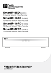
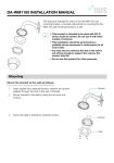
Video
Encoder
Operation Manual
DE-1104
DE-1108
Powered by
Before reading this manual
English
This operation manual contains basic instructions on installing and using DirectIP™ Video Encoder, an IDIS product.
Users who are using this product for the first time, as well as users with experience using comparable products, must read
this operation manual carefully before use and heed to the warnings and precautions contained herein while using the
product. Safety warnings and precautions contained in this operation manual are intended to promote proper use of the
product and thereby prevent accidents and property damage and must be followed at all times.
Once you have read this operation manual, keep it at an easily accessible location for future reference.
• The manufacturer will not be held responsible for any product damage resulting from the use of unauthorized parts and
accessories or from the user’s failure to comply with the instructions contained in this operation manual.
• It is recommended that first-time users of DirectIP™ Video Encoder and individuals who are not familiar with its use seek
technical assistance from their retailer regarding product installation and use.
• If you need to disassemble the product for functionality expansion or repair purposes, you must contact your retailer and
seek professional assistance.
• Both retailers and users should be aware that this product has been certified as being electromagnetically compatible for
commercial use. If you have sold or purchased this product unintentionally, please replace with a consumer version.
Safety Precautions
CAUTION
RISK OF ELECTRIC SHOCK
DO NOT OPEN
CAUTION: TO REDUCE THE RISK OF ELECTRIC SHOCK,
DO NOT REMOVE COVER (OR BACK).
NO USER-SERVICEABLE PARTS INSIDE.
REFER SERVICING TO QUALIFIED SERVICE PERSONNEL.
The lightning flash with arrowhead symbol, within an equilateral triangle, is intended to alert the user to the presence of
uninsulated "dangerous voltage" within the product’s enclosure that may be of sufficient magnitude to constitute a risk of electric
shock.
The exclamation point within an equilateral triangle is intended to alert the user to the presence of important operating and
maintenance (servicing) instructions in the literature accompanying the appliance.
2
Safety Precautions
All the safety and operating instructions should be read before the
appliance is operated.
2. Retain Instructions
The safety and operating instructions should be retained for future
reference.
3. Cleaning
Unplug this equipment from the wall outlet before cleaning it. Do not use
liquid aerosol cleaners. Use a damp soft cloth for cleaning.
4. Attachments
Never add any attachments and/or equipment without the approval of the
manufacturer as such additions may result in the risk of fire, electric shock or
other personal injury.
5. Water and/or Moisture
Do not use this equipment near water or in contact with water.
6. Ventilation
Place this equipment only in an upright position. This equipment has an
open-frame Switching Mode Power Supply (SMPS), which can cause a fire
or electric shock if anything is inserted through the ventilation holes on the
side of the equipment.
7. Accessories
Do not place this equipment on an unstable cart, stand or table. The
equipment may fall, causing serious injury to a child or adult, and serious
damage to the equipment. Wall or shelf mounting should follow the
manufacturer’s instructions, and should use a mounting kit approved by
the manufacturer.
English
Important Safeguards
1. Read Instructions
13. Servicing
Do not attempt to service this equipment yourself. Refer all servicing to
qualified service personnel.
14. Damage requiring Service
Unplug this equipment from the wall outlet and refer servicing to qualified
service personnel under the following conditions:
A. When the power-supply cord or the plug has been damaged.
B. If liquid is spilled, or objects have fallen into the equipment.
C. If the equipment has been exposed to rain or water.
D. If the equipment does not operate normally by following the operating
instructions, adjust only those controls that are covered by the operating
instructions as an improper adjustment of other controls may result in
damage and will often require extensive work by a qualified technician to
restore the equipment to its normal operation.
E. If the equipment has been dropped, or the cabinet damaged.
F. When the equipment exhibits a distinct change in performance - this
indicates a need for service.
15. Replacement Parts
When replacement parts are required, be sure the service technician has
used replacement parts specified by the manufacturer or that have the
same characteristics as the original part. Unauthorized substitutions may
result in fire, electric shock or other hazards.
16. Safety Check
Upon completion of any service or repairs to this equipment, ask the service
technician to perform safety checks to determine that the equipment is in
proper operating condition.
17. Field Installation
This installation should be made by a qualified service person and should
conform to all local codes.
18. Correct Batteries
This equipment and cart combination should be moved with care. Quick
stops, excessive force, and uneven surfaces may cause the equipment and
cart combination to overturn.
8. Power Sources
This equipment should be operated only from the type of power source
indicated on the marking label. If you are not sure of the type of power,
please consult your equipment dealer or local power company.
You may want to install a UPS (Uninterruptible Power Supply) system for
safe operation in order to prevent damage caused by an unexpected power
stoppage. Any questions concerning UPS, consult your UPS retailer.
9. Power Cords
Operator or installer must remove power and TNT connections before
handling the equipment.
10. Lightning
For added protection for this equipment during a lightning storm, or when
it is left unattended and unused for long periods of time, unplug it from the
wall outlet and disconnect the antenna or cable system. This will prevent
damage to the equipment due to lightning and power-line surges.
11. Overloading
Do not overload wall outlets and extension cords as this can result in the risk
of fire or electric shock.
12. Objects and Liquids
Never push objects of any kind through openings of this equipment as they
may touch dangerous voltage points or short out parts that could result in a
fire or electric shock. Never spill liquid of any kind on the equipment.
Warning: Risk of explosion if battery is replaced by an incorrect type.
Dispose of used batteries according to the instructions.
19. Tmra
A manufacturer’s maximum recommended ambient temperature (Tmra)
for the equipment must be specified so that the customer and installer may
determine a suitable maximum operating environment for the equipment.
20. Elevated Operating Ambient Temperature
If installed in a closed or multi-unit rack assembly, the operating ambient
temperature of the rack environment may be greater than room ambient.
Therefore, consideration should be given to installing the equipment in an
environment compatible with the manufacturer’s maximum rated ambient
temperature (Tmra).
21. Reduced Air Flow
Installation of the equipment in the rack should be such that the amount of
airflow required for safe operation of the equipment is not compromised.
22. Mechanical Loading
Mounting of the equipment in the rack should be such that a hazardous
condition is not caused by uneven mechanical loading.
23. Circuit Overloading
Consideration should be given to connection of the equipment to supply
circuit and the effect that overloading of circuits might have on over current
protection and supply wiring. Appropriate consideration of equipment
nameplate ratings should be used when addressing this concern.
24. Reliable Earthing (Grounding)
Reliable grounding of rack mounted equipment should be maintained.
Particular attention should be given to supply connections other than direct
connections to the branch circuit (e.g., use of power strips).
3
English
In-Text
Symbol
Type
Caution
Note
Description
Important information concerning a specific function.
Useful information concerning a specific function.
User’s Caution Statement
Caution: Any changes or modifications to the equipment not expressly approved by the party responsible for compliance
could void your authority to operate the equipment.
FCC Compliance Statement
THIS EQUIPMENT HAS BEEN TESTED AND FOUND TO COMPLY WITH THE LIMITS FOR A CLASS A DIGITAL DEVICE, PURSUANT TO PART 15 OF THE
FCC RULES. THESE LIMITS ARE DESIGNED TO PROVIDE REASONABLE PROTECTION AGAINST HARMFUL INTERFERENCE WHEN THE EQUIPMENT IS
OPERATED IN A COMMERCIAL ENVIRONMENT. THIS EQUIPMENT GENERATES, USES, AND CAN RADIATE RADIO FREQUENCY ENERGY AND IF NOT
INSTALLED AND USED IN ACCORDANCE WITH THE INSTRUCTION MANUAL, MAY CAUSE HARMFUL INTERFERENCE TO RADIO COMMUNICATIONS.
OPERATION OF THIS EQUIPMENT IN A RESIDENTIAL AREA IS LIKELY TO CAUSE HARMFUL INTERFERENCE, IN WHICH CASE USERS WILL BE REQUIRED
TO CORRECT THE INTERFERENCE AT THEIR OWN EXPENSE.
WARNING: CHANGES OR MODIFICATIONS NOT EXPRESSLY APPROVED BY THE PARTY RESPONSIBLE FOR COMPLIANCE COULD VOID THE USER’S
AUTHORITY TO OPERATE THE EQUIPMENT. THIS CLASS OF DIGITAL APPARATUS MEETS ALL REQUIREMENTS OF THE CANADIAN INTERFERENCE
CAUSING EQUIPMENT REGULATIONS.
WEEE (Waste Electrical & Electronic Equipment)
Correct Disposal of This Product
(Applicable in the European Union and other European countries with separate collection systems)
This marking shown on the product or its literature, indicates that it should not be disposed with other household wastes at the
end of its working life. To prevent possible harm to the environment or human health from uncontrolled waste disposal, please
separate this from other types of wastes and recycle it responsibly to promote the sustainable reuse of material resources.
Household users should contact either the retailer where they purchased this product, or their local government office, for
details of where and how they can take this item for environmentally safe recycling.
Business users should contact their supplier and check the terms and conditions of the purchase contract. This product should
not be mixed with other commercial wastes for disposal.
4
English
Copyright
© 2014 IDIS Co., Ltd.
IDIS Co., Ltd. reserves all rights concerning this operation manual.
Use or duplication of this operation manual in part or whole without the prior consent of IDIS Co., Ltd. is strictly prohibited.
Contents of this operation manual are subject to change without prior notice for reasons such as functionality enhancements.
Registered Trademarks
IDIS is a registered trademark of IDIS Co., Ltd.
Other company and product names are registered trademarks of their respective owners.
The information in this manual is believed to be accurate as of the date of publication. We are not responsible for any problems resulting
from the use thereof. The information contained herein is subject to change without notice. Revisions or new editions to this publication
may be issued to incorporate such changes.
The software included in this product contains some Open Sources. You may obtain the complete corresponding source code from us.
See the Open Source Guide on the software CD (OpenSourceGuide\OpenSourceGuide.pdf ) or as a printed document included along with
the User’s Manual.
5
Table of Contents
English
1
2
6
Part 1 - Introduction
7
Product Features. . . . . . . . . . . . . . . . . . . . . . . . . . . . . . . . . . . . . . . . . . . . . . . . . . . . . . . . . . . . . . . . . . . . . . . . . . . . 7
Accessories. . . . . . . . . . . . . . . . . . . . . . . . . . . . . . . . . . . . . . . . . . . . . . . . . . . . . . . . . . . . . . . . . . . . . . . . . . . . . . . . . . 9
Overview. . . . . . . . . . . . . . . . . . . . . . . . . . . . . . . . . . . . . . . . . . . . . . . . . . . . . . . . . . . . . . . . . . . . . . . . . . . . . . . . . . . 9
Part 2 - Miscellaneous
11
Troubleshooting. . . . . . . . . . . . . . . . . . . . . . . . . . . . . . . . . . . . . . . . . . . . . . . . . . . . . . . . . . . . . . . . . . . . . . . . . . . . 11
Specifications. . . . . . . . . . . . . . . . . . . . . . . . . . . . . . . . . . . . . . . . . . . . . . . . . . . . . . . . . . . . . . . . . . . . . . . . . . . . . . 11
Part 1 - Introduction
English
Product Features
This video encoder compresses live video from analog cameras and transmits the video over Ethernet connections. This
encoder offers the following features:
• 4/8 composite video input connectors
• Multi-streaming for monitoring and recording
• H.264 compression algorithm
• Four levels of video compression and various video compression resolutions
• DirectIPTM protocol supported
• Convenient firmware upgrades via network
• Firmware duplication and autorecovery functions to enhance system stability
• Event detection functions: motion, video loss, tampering
• 4-channel audio in
• Support of PTZ camera control via RS485 interface
• Configuration of encoder settings and integrated management of multiple encoders on the NVR (Network Video
Recorder)
This manual covers the 4- and 8-channel video encoders. The video encoders are identical except for the number of cameras
that can be connected. For simplicity, the illustrations and descriptions in this manual refer to the 8-camera model.
7
Video Encoder Connection Diagram
English
Analog Camera
NVR (Network Video Recorder)
AUDIO OUT
2
HDMI
VGA OUT
NETWORK
CLIENT
RS -232
4
A/1 A/2 A/3 A/4 G Tx Rx
B
D
F
H
Video Encoder
1
3
eSATA
NC C NO ARI G
AUDIO IN
RS-485
- +
Ext.
A
C
VIDEO IN
CAUTION : TO REDUCE THE RISK OF ELECTRIC SHOCK.
DO NOT REMOVE COVER (OR BACK).
NO USER-SERVICEABLE PARTS INSIDE.
REFER SERVICING TO QUALIFIED
SERVICE PERSONNEL.
CAUTION
CAUTION : TO REDUCE THE RISK OF ELECTRIC SHOCK.
DO NOT REMOVE COVER (OR BACK).
NO USER-SERVICEABLE PARTS INSIDE.
REFER SERVICING TO QUALIFIED
SERVICE PERSONNEL.
RISK OF ELECTRIC SHOCK
DO NOT OPEN
E
G
VIDEO IN / PoE
CAUTION
RISK OF ELECTRIC SHOCK
DO NOT OPEN
VIDEO IN / PoE
VIDEO IN
AUDIO IN
NC C NO ARI G
RS-485
- +
Ext.
A
C
E
G
NETWORK
CLIENT
B
D
F
H
eSATA
1
3
2
4
Video Encoder
VGA OUT
AUDIO OUT
HDMI
A/1 A/2 A/3 A/4 G Tx Rx
RS -232
NVR (Network Video Recorder)
Analog Camera
100-240V~
Types of Cables
RS485 Communication Cable
Analog BNC Cable
H
D
F
E
B
NETWORK
CLIENT
RS -232
Ext.
3
4
2
HDMI
VGA OUT
AUDIO OUT
AUDIO IN
RISK OF ELECTRIC SHOCK
DO NOT OPEN
CAUTION
CAUTION : TO REDUCE THE RISK OF ELECTRIC SHOCK.
DO NOT REMOVE COVER (OR BACK).
NO USER-SERVICEABLE PARTS INSIDE.
REFER SERVICING TO QUALIFIED
SERVICE PERSONNEL.
eSATA
1
NC C NO ARI G
A/1 A/2 A/3 A/4 G Tx Rx
RS-485
- +
VIDEO IN
A
C
VIDEO IN / PoE
G
Video Encoder
Analog Camera
Video Encoder
8
NVR (Network Video Recorder)
LAN Cable (Data + DC48V Power)
100-240V~
English
Accessories
Upon unpacking the product, check the contents inside to ensure that all the following contents are included.
• Video Encoder
• User Guide and Instruction Manual (This document)
Overview
Front Panel
1
1
Power LED
2
Network LED
3
2
3
Factory Reset Switch
1 Power LED
Displays system operating status
2 Network LED
Displays network connection status
LED Status Indications
LED
Status
Off
Power LED
Blinking
Network LED
Blinking
On
Description
No power connection
System booting or upgrading
System operating
Normal network connection
3 Factory Reset Switch
Use to return all settings to the original factory settings. Connect the power and poke a straightened paperclip into the factory
reset switch hole. Hold the reset switch until the encoder’s internal buzzer sounds twice. Release the reset switch, and all of the
encoder’s settings are now at the original settings it had when it left the factory.
9
Rear Panel
English
2
3
4
1
1
RS485
5
DC12V In
2
Audio In
3
Video In
4
5
Network + PoE Power In
1 RS485
Connect a PTZ camera. Connect the camera’s TX+/RX+ and TX–/RX– to the encoder’s + and –.
For more information on RS485 connections, refer to the PTZ camera’s manufacturer’s user’s manual.
2 Audio In
Connect to an audio source.
3 Video In
Connect coaxial cables from the video sources.
4 Network + PoE Power In
Connect a Cat5e cable with an RJ-45 jack. The video encoder is capable of connecting to networks via an Ethernet connector
and also receives power (DC48V) from the NVR.
5 DC12V In
Connect the two wires of the power adapter to these ports. Be careful not to cross the DC12V and ground (GND) wires. Booting
will commence once connected to a power supply.
• The network connector is not designed to be connected directly with cable or wire intended for outdoor use.
• Press down on the button and insert the cable into the opening when you connect the RS485 and power connectors.
Release the button and then pull on the cable slightly to ensure it is held securely in place. To disconnect the cable, press
down on the button again and pull the cable out.
• Ground the power port’s ground terminal before use.
• Organize the power cable so that it will not cause people to trip over or become damaged from chairs, cabinets, desks,
and other objects in the vicinity. Do not run the power cable underneath a rug or carpet.
• Do not connect multiple devices to a single power outlet.
10
Part 2 - Miscellaneous
English
Troubleshooting
Problem
Check
• Check the LAN cable.
Power LED will not turn on
• Check that the power cable is connected or the NVR has power.
The system is unable to recognize
network interface
• Check the LAN cable.
• Check the network LED.
Specifications
Model
DE-1104
Input
Video
DE-1108
4 BNC
8 BNC
Compression
H.264
Resolution
720x480(960x480), 640x360, 360x240 (NTSC)
720x576(960x576), 640x360, 360x288 (PAL)
Bitrate Control
Frame Rate
Inputs/
Outputs
Environmental
Conditions
General
VBR
120ips @ 720x480(960x480)
(Quadruple Stream)
240ips @ 720x480(960x480)
(Quadruple Stream)
Audio Input
4 RCA
RS485
1 Port
Ethernet
10M/100M/1Gbps
DC12V Input
Terminal Blocks
LED
Power(Status), Network
Button/Switch
Reset
Operating Temperature
32°F to 104°F (0°C ~ 40°C)
Operating Humidity
0% ~ 90%
Dimensions (W x H x D)
7.9” x 1.7” x 5.7” (200mm x 44mm x 145mm)
Shipping Dimensions
(W x H x D)
10.1” x 4.1” x 7.4” (258mm x 103mm x 188mm)
Unit Weight
1.9 lbs. (0.84kg)
Shipping Weight
2.7 lbs. (1.22kg)
Power Supply
DC12V or PoE (IEEE802.3af class3)
Power Consumption
Max. 12W
Approval
FCC, CE
These product specifications may change without prior notice.
Ver. 1.0
11
IDIS Co., Ltd.
For more information, please visit at
www.idisglobal.com