1
Marex SB
Manual / Marine
Version 2.10
15.07.2003
Short Instructions
Please do also see the general advice in chapter 1.
Step
1
Description
Select engine type (chapter 2 "overview")
Assembly
2
Adjust SYSCON switch board in accordance with engine type (chapter 2 "overview")
3
-
Wire components and adjust switches
Power supply (chapter 3.1)
Control head (chapter 3.2)
Attention: Enter the control head ID and write it down.
Throttle and gear control ("mechanical" chapter 3.3, "electrical" chapter 3.4)
Extra functions if necessary (alarm, engine start interlock, idle speed relay, chapter 3.5
ff.)
Commissioning
4
Enter control heads (chapter 4.2)
Enter additional functions of control heads if applicable.
5
For mechanical throttle control: enter nominal value for idle speed (chapter 4.3)
6
For mechanical gear shifting: adjust position ahead / astern
(chapter 4.4)
7
Enter extra functions if necessary (power boost, increased idle speed, see chapter 4.3,
synchronization, buzzer in neutral, change of control station, see chapter 4.2).
Mooring Trial
8
Adjustment of delay times for gear shifting (chapter 4.4)
Adjustment of power boost if applicable (chapter 4.3)
Adjustment of increased idle speed if applicable (chapter 4.3)
Sea Trial
9
Adjustment of reversing delay times (chapter 4.4)
How to operate the system is described in chapter 5.
In case of malfunction, an error analysis as explained in chapter 6 has to be carried out.
Imprint:
The copyright of this user manual remains the property of Bosch Rexroth AG.
Included are instructions and technical drawings which may not be reproduced or
copied either in part or whole, nor may they be used for evaluation or distributed for
competition purposes.
The diagrams and drawings used in this manual are for guidelines only and are not be
used for the actual design.
This edition supersedes all previous ones.
Order No.: 883 890 060 3
Bosch Rexroth AG
Department Marine Technique
Bartweg 13
30453 Hannover
P. O. Box 91 07 62
30427 Hannover
Tel.:
Fax.:
e-mail:
Internet:
+49 (0)5 11-2136-2 51
+49 (0)5 11-2136-1 62
[email protected]
http://www.boschrexroth.de
Table of Contents
Page
1 General
1.1 System components
1.2 General preconditions for the operation
1.3 Mounting advice
1.4 Operating advice
1
2
2
2
2 Overview
2.1 Single engine
2.2 Twin engine
3
5
3 Wiring
3.1 Voltage supply
3.2 Control head
3.3 Mechanical throttle control / gear shifting
3.4 Electrical throttle control / gear shifting
3.5 Alarm relays
3.6 Engine start interlock
3.7 Idle gas relay
7
7
10
11
15
16
18
4 Adjustment
4.1 Hardware configuration
4.2 Control head
4.3 Speed
4.4 Gearing
4.5 Reset to default
19
20
23
25
28
5 Operation
5.1 General
5.2 Activation and request control station
5.3 Station transfer
5.4 Warming Up
5.5 Increased idle speed
5.6 Synchronising
29
30
31
32
32
32
6 Error analysis
6.1 Error at control station
6.2 Error indication control panel
33
34
Appendix
Control unit
40
1
1 General
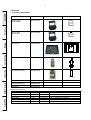
1.1 System components
General
Overview
Wiring
Adjustment
Operation
Error Analysis
Designation
Code No.
Control head
(single engine)
362 241 100 0
Control head
(twin engine)
362 241 000 0
Control unit
346 068 000 0
DC actuator
323 698 020 0
I/O-extension board
346 068 721 2
Synchro-board
346 068 730 2
Push-/Pull-cable 2m
323 699 415 2
Mounting kit
323 699 006 2
Appendix
Additionally required:
Data cable
Supply cable
Throttle cable
Gearing cable
Cable alarm
Cable start interlock
Cable idle gas
LIYCY
Ölflex 100
LIYCY
LIYCY
LIYCY
LIYCY
LIYCY
Photo
4 x 1mm²
2 x 2,5mm²
2 x 0,75mm²
7 x 1mm²
2 x 0,75mm²
2 x 0,75mm²
2 x 0,75mm²
Symbol
1
2
3
4
for electrical throttle control only
for electrical gear shifting only
if alarm system is connected
if engine start interlock is connected
if idle gas is connected
2
1.2 General preconditions for the operation
Indication of the current cruising command*
The current cruising command (speed, gearing position) must be indicated on every control station.
General
(According to classification rules)
If, from any control station, any other station is visible, the indication of current cruising command and
active control station is not necessary (e. g. on small yachts).
Capacity of independent actuation*
Besides the remote control, a second possibility of controlling speed and gearing must be provided.
Overview
Indication of active control station*
It must be indicated on every control station which control station is in command.
Wiring
Emergency stop-button*
A separate emergency stop-button for the engine must be installed on every control station
independent from the remote control.
*These components are not included in the MAREX SB delivery.
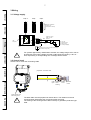
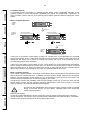
1.3 Mounting advice
shielded cable
sleeving
pressure screw
Adjustment
Cables to be connected to the control unit must always be provided with the metallic cable joints
supplied. The joints are mounted as shown below:
Mounting work must be done only if the system is in voltage-free condition. The power supply must be
secured against activation in this case.
Mounting and commissioning work must be carried out by skilled personnel and in accordance with
the manual only.
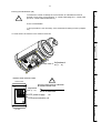
1.4 Operating advice
Do not reach into the actuator while it is in operation. You risk injuring.
The remote control MAREX SB has been designed for the control of Diesel engines. If it is applied for
petrol or gas propulsion systems, its components must be installed outside the hazardous area. The
instructions for hazardous areas have to be followed.
Error Analysis
Inserted sealing
Appendix
outside cone
Operation
cable
conductors
3
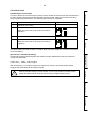
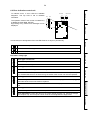
2 Overview
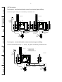
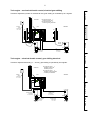
2.1 Single engine
General
Single engine – mechanical throttle control and gear shifting
Throttle and gear shifting are operated by mechanical rods.
1
Overview
1
2
3
4
5
6
7
8
shielded cable
type LIYCY
4 x 1 mm2
SYSCON
S1
S2
Wiring
70 mm
100 N
Adjustment
70 mm
100 N
Single engine - electrical throttle control, mechanical gear shifting
The throttle is adjusted electrically (4 ... 20 mA), the gears are shifted by mechanical rods.
1
Operation
1
2
3
4
5
6
7
8
shielded cable
type LIYCY
4 x 1 mm2
SYSCON
S1
Error Analysis
shielded cable
type LIYCY
2 x 0,75 mm2
4...20 mA
Appendix
70 mm
100 N
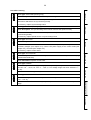
4
1
2
3
4
5
6
7
8
SYSCON
shielded cable
type LIYCY
4 x 1 mm2
A2
shielded cable
type LIYCY
7 x 1 mm2
70 mm
100 N
Overview
1
Wiring
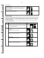
Throttle is actuated by mechanical rods, gear shifting is controlled by 24 V-signals.
General
Single engine - mechanical throttle control, electrical gear shifting
Single engine – electrical throttle control and gear shifting
Throttle is adjusted electrically (4 ... 20 mA), the gears are shifted using 24 V-signals.
Adjustment
24 V
1
Operation
SYSCON
shielded cable
type LIYCY
4 x 1 mm2
shielded cable
type LIYCY
2 x 0,75 mm2
shielded cable
type LIYCY
7 x 1 mm2
4...20 mA
Error Analysis
1
2
3
4
5
6
7
8
Appendix
24 V
5
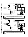
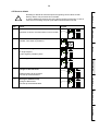
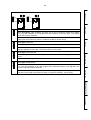
2.2 Twin engine
General
Twin engine – mechanical throttle control, mechanical gear shifting
Throttle and gear shifting are controlled by mechanical rods.
1
Overview
shielded
cable
type LIYCY
4 x 1 mm2
1
2
3
4
5
6
7
8
1
1
2
3
4
5
6
7
8
SYSCON
port
A1
A2
SYSCON
starboard
A1
A2
Wiring
shielded cable
typeLIYCY
2 (4) x 1 mm2
70 mm
100 N
70 mm
100 N
70 mm
100 N
70 mm
100 N
Adjustment
Twin engine – electrical throttle control, mechanical gear shifting
Throttle is actuated electrically (4 ... 20 mA), the gears are shifted by mechanical rods.
1
Operation
shielded
cable
type LIYCY
4 x 1 mm2
1
2
3
4
5
6
7
8
SYSCON
I/O-extension board 1:
actuation rpm port
I/O-extension board 2:
actuation rpm starboard
port
starboard
A1
A2
Error Analysis
1
2
4...20 mA
shielded cable
type LIYCY
2 x 0,75 mm2
Appendix
70 mm
100 N
4...20 mA
shielded cable
type LIYCY
2 x 0,75 mm2
70 mm
100 N
6
Throttle is adjusted by means of mechanical rods, gear shifting is controlled by 24 V-signals.
1
I/O-extension board 1:
actuation gearing port
I/O-extension board 2:
actuation gearing starboard
SYSCON
port
starboard
A1
Overview
shielded
cable
type LIYCY
4 x 1 mm2
1
2
3
4
5
6
7
8
General
Twin engine – mechanical throttle control, electrical gear shifting
A2
1
70 mm
100 N
70 mm
100 N
24 V
24 V
shielded cable
type LIYCY
7 x 1 mm2
Twin engine – electrical throttle control, gear shifting electrical
Throttle is adjusted electrically (4 ... 20 mA), gear shifting is operated by 24V-signals.
Adjustment
shielded cable
type LIYCY
7 x 1 mm2
Wiring
2
port
starboard
1
2
4...20 mA
shielded cable
type LIYCY
2 x 0,75 mm2
4...20 mA
shielded cable
type LIYCY
2 x 0,75 mm2
24 V
shielded cable
type LIYCY
7 x 1 mm2
Error Analysis
I/O-extension board 1:
actuation gearing port
actuation rpm port
I/O-extension board 2:
actuation gearing starboard
actuation rpm starboard
SYSCON
24 V
shielded cable
type LIYCY
7 x 1 mm2
Appendix
shielded
cable
type LIYCY
4 x 1 mm2
1
2
3
4
5
6
7
8
Operation
1
7
3 Wiring
General
3.1 Voltage supply
voltage
12...24 V DC
voltage
12 V DC
voltage
24 V DC
Overview
7
7
7
1
2
3
4
5
6
7
8
1
2
3
4
5
6
7
8
1
2
3
4
5
6
7
8
GND
2
LED readyness
switch for configuration
of engine type
(see chapter 2 overview)
supply line 2,5mm2,
length. 10m max
screened
Vcc
1
Wiring
fuse
16A T
main
switch
+
-
12V / 24V DC
10 A nominal current
30 A peak current
(acc. to Lloyds Register)
fuse
10A T
earthing at one of the 4 mounting screws directly
(connection to ship mass)
Adjustment
!
For systems approved by classification societies, the voltage range 12V or has to
be selected. If the supply voltage exceeds or falls below the range by +30% or 25% respectively, a corresponding error message will be issued.
3.2 Control head
Advice how to mount the connecting cable
Operation
preparation connection cable
100 mm
Error Analysis
male
taper
shieldedcable
sleeving
sealing
insert
pressure
-screw
loosen screws and
lift housing cover
Appendix
!
The data cable must be prepared as shown above. The cables must not be
squeezed when assembling the components after the wiring.
The sealing of the housing must be fitted correctly to guarantee protection type
IP65.
8
To enable the control to identify the control heads, an individual ID must be
entered once at every control head (e. g. control head bridge ID 1, control head
port ID 2, control head starboard ID 3)
!
General
Entering the identification (ID)
à This procedure is not necessary, if the automatic ID setting is used. (Chapter
4.2)
On every control head, an individual
ID must be entered once.
7
6
5
4
3
2
1
X1
adjustment
ID (1...6)
ID 0 is not admissible.
LED power supply
ok
LEDcommunication ok
port side
Operation
!
starboard side
Error Analysis
bottom side control head
Appendix
Adjustment
ID (1...6)
Adjustment
Wiring
To enter the ID, the housing cover must be removed.
Overview
ID 0 is not admissible.
9
Wiring control head
General
optional switch: station tranfer interlock
(required for ECR stations according to classification rules)
The IDs of the control heads
must be different.
!
control head
ID 1
gb
gr
1
Overview
gr
gb
br
ws
2
1
7
6
5
gr
4
gb
3
br
2
ws
1
7
6
5
4
3
2
1
control head
ID 2
+
gr
gb
br
ws
control head
ID 3
7
6
5
gr
4
gb
3
br
2
ws
1
7
6
5
4
3
2
1
gr
gb
br
ws
7
6
5
4
3
2
1
7
6
5
4
3
2
1
!
bridge
at last
head
2
3
screened line
(LIYCY)
4 x 1 mm2
total length 60m max.
4
br
ws
1
2
Wiring
screened line
grounded at both ends
Terminal
1
2
3
4
5
6
7
Terminal assignment control head
Adjustment
Designation
0V
+8 V
CAN –
CAN +
CAN end
switch switch +
Colour
white (ws)
brown (br)
yellow (gb)
green (gr)
At the last control head, a bridge must be connected between terminals 4 and 5.
!
Operation
Special application: twin engine with mechanical throttle control and gear shifting
Example: 2 control head
gb
The IDs of the control heads
must be different.
!
remove bridge
terminal 2/3
!
Error Analysis
gb
1
gr
2
gb
gr
1
control head
control head
ID 1
gr
gb
br
ws
7
6
5
4
3
2
1
gr
1
7
6
5
gr
4
gb
3
br
2
ws
1
gr
gb
br
ws
7
6
5
4
3
2
1
!
Appendix
1
ws
2
shielded cable
4 x 1 mm2
earthed at both ends
2
7
6
5
4
3 bridge
2 at last
1 head
3
4
1
2
port
starboard
4
br
2
ID 2
2
3
1
shielded cable
2 (4) x 1 mm2
earthed at both ends
10
actuator
1
actuator
2
General
3.3 Mechanical throttle control and gear shifting
SYSCON
1
2
Overview
3
2
1
2
1
The setting of switchboard SYSCON (switches 1 – 6) assigns the function (speed or gear control) to
the actuators (see chapter 2 overview).
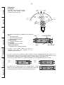
3.3.1 Push-/pull-cable
The mechanical connection between actuator and lever for throttle adjustment or gear control at the
engine is done by push-/pull-cables.
Wiring
1
2
3
110
33 max
10-32 UNF-2A
**
76 stroke
22,1
Adjustment
170 + 3 for half the stroke
min 5
9,46
9,46
6,35
When laying push-/pull cables as few direction changes as possible should be
made. The efficiency of the cables decreases with every deflection.
!
Deflection angle 90°
Deflection angle 360°
usable force = 82% of the force applied
usable force = 55% of the force applied
Operation
radial excursion: 8° max. to all sides
Error Analysis
**
min 5
Appendix
8,5
3,27
11
3.3.2 Mounting of the actuator
General
!
Mounting work may only be carried out if the actuator
is idle.
Risk of injury!
Overview
3.3.3. Connection at the throttle and gear adjusting lever
To fix the push-/pull-cable at the adjusting lever, a ball joint may be used.
"s"
ball joint
Wiring
hexagone nut
counter bearing
Adjustment
!
When adjusting the traveling range of the actuator (stroke), it must be ensured
that both markings remain visible in the end positions.
The travel may not be blocked by exterior mechanical stops. Misadjustment may
lead to blocking and distruction of the electric actuators.
Operation
stroke 70 mm
Error Analysis
3.4 Electrical throttle control and gear shifting
Electrical throttle control
71
72
73
74
75
76
77
78
79
80
81
82
1
2
3
4
+
Appendix
4...20 mA
galvanically separated
(max. 500 Ohm)
-
shielded cable
Typ:LIYCY
2 x 0,75 mm2
earthed at both ends
geerdet
ECU, EDC
Engine Control Unit
Engine Digital Control
12
72
73
74
75
76
77
78
79
80
81
screened cable
type LIYCY
7 x 1 mm2
grounded at both ends
1
2
3
4
LED set ahead (73)
LED set astern (75)
ahead
Vcc, 2A
astern
Vcc, 2A
82
Overview
71
Indication gear condition
General
Electrical gear shifting without feedback
solenoid valve
gear feedback
off
relay with
free-wheeling diode
Wiring
1
1
2
3
4
Solenoid valve not included in MAREX SB delivery.
The power supply for the gearbox must be fused separately.
Adjustment
Operation
If inductive loads shall be switched, these must be provided with a free-wheeling diode.
If not, the digital output may be destroyed.
Error Analysis
!
reversing gearbox
Appendix
An emergency manual override for gear shifting must be provided.
13
Electrical gear shifting with separate feedback
71
Indication gear condition
72
73
74
75
76
77
78
79
80
81
82
General
screened cable
type LIYCY, 7 x 1 mm2
grounded at both ends
1
2
3
4
LED set ahead (73)
LED set astern (75)
Overview
LED act. astern (78)
LED act. astern (76)
Voraus
Vcc, 2A
Zurück
Vcc, 2A
solenoid valve
with free-wheeling diodes
1
1
2
3
4
gear feedback
on
sep. feedback
on
pressure switch
Wiring
Solenoid valve and pressure switch are not included in the MAREX SB delivery.
The power supply for the gearbox must be fused separately.
An emergency manual override to shift gears must be provided.
Adjustment
!
reversing gearbox
If inductive loads shall be switched, these must be provided with a free-wheeling diode.
If not, the digital output may be destroyed.
Electrical gear shifting with collective feedback
71
Indication condition gearbox
72
73
74
75
76
77
78
79
80
81
Operation
screened cable
type LIYCY, 7 x 1 mm2
grounded at both ends
1
2
3
4
LED set ahead (73)
LED set astern (75)
LED collectivefeedback (76)
Voraus
Vcc, 2A
Zurück
Vcc, 2A
Error Analysis
solenoid valve
with free-wheeling diodes
1
1
2
3
4
gear feedback
on
sep. feedback
off
pressure switch
Solenoid valve and pressure switch are not included in the MAREX SB delivery.
Appendix
The power supply for the gearbox must be fused separately.
An emergency manual override to shift gears must be provided.
!
reversing gearbox
If inductive loads shall be switched, these must be provided with a free-wheeling diode.
If not, the digital output may be destroyed.
82
14
General
Power supply for electrical gear shifting
71
Overview
1
2
3
4
72
fuse
2A T
GND
supply line
length max. 10m
-
2 x 1 mm2,
The power supply shown above is recommended according to the classification rules.
Wiring
Vcc
+
1
2
3
4
1
Vcc
!
2
GND
71 72
Vcc
GND
When the control unit supplies the voltage for the electrical gear control, the power
supply is not protected by fuse. In this case, the control unit must be protected
separately (see chapter 3.1 "power supply").
Appendix
!
Error Analysis
Operation
1
2
3
4
Adjustment
Alternatively, the control unit may supply the voltage for the electrical gear control:
15
Mounting the I/O-extension boards
General
1
2
Overview
X101
X102
viewing direction
2
Wiring
X31
I/O-extension board II (actuation starboard
X101
1
control unit
)
X102
I/O-extension board I (actuation port
)
Adjustment
3.5 Alarm relays
2
1
Operation
2
1
Error Analysis
LED alarm relay
!
potential-free
relay contact
closed in case
of error
max. 30 V DC
max. 0,5
A
shielded cable
type LIYCY
2 x 0,75 mm2
earthed at both ends
If inductive loads shall be switched, these must be provided with a free-wheeling diode.
If not, the digital output may be destroyed.
Appendix
16
twin engine
configuration
start interlock
2
2
supply
battery
shielded cable
type LIYCY
2 x 0,75 mm2
shielded cable
type LIYCY
2 x 0,75 mm2
-
+
-
+
+
-
engine
starterbattery
+
+
-
engine
+
-
engine
port
connection to
I/O-extension board 1
Overview
1
2
3
4
1
starboard
connection to
I/O-extension board 2
The relay "start interlock" is closed whenever the active control head is in neutral or warming up (see
5.4 "warming up") is active.
Wiring control unit
Wiring
single engine
General
3.6 Engine start interlock
engine start interlock via control unit
Adjustment
closed when,
lever in neutral or
warming up active
1
shielded cable
type LIYCY
earthed at both ends
If inductive loads shall be switched, these must be provided with a free-wheeling diode.
If not, the digital output may be destroyed.
!
Wiring I/O-extension board
1
2
3
4
LED startinterlock
2
1
2
3
4
closed when,
lever in neutral or
Warming Up active
potential-free
relay contact
max. 30V DC
max. 2 A
configuration
start interlock
71
72
73
74
75
76
77
78
79
80
81
82
shielded cable
type LIYCY
2 x 0,75 mm2
earthed at both ends
!
If inductive loads shall be switched, these must be provided with a free-wheeling diode.
If not, the digital output may be destroyed.
Operation
LED start interlock
2
Error Analysis
1
potential-free
relay contact
max. 30 V DC
max. 0,5
A
Appendix
2
17
Two special cases must be considered when wiring the engine start interlock
General
!
Engine start interlock, special application 1:
Twin engine with mechanical throttle control and gear shifting
Overview
1
1
1
2
3
4
5
6
7
8
1
2
3
4
5
6
7
8
port
A1
A2
starboard
A1
A2
Wiring
port
starboard
Adjustment
shielded cable
type LIYCY
2 x 0,75 mm2
+
engine
shielded cable
type LIYCY
2 x 0,75 mm2
+
-
+
-
+
-
engine
Engine start interlock, special application 2:
Using the function "idle gas relay" on twin engines
Operation
configuration
idle gas relay
2
1
2
3
4
1
2
Error Analysis
+
-
supply
battery
-+
+
-
engine
Appendix
+
- Starter-
+
- Starterbattery
engine
battery
port
!
starboard
Engine start interlock will be released if both levers of the control heads (port and
starboard) are in neutral position or warming up is active.
18
Single Engine
General
3.7 Idle gas relay
Twin Engine
1
1
idle gas
idle gas port
idle gas starboard
st
The idle gas relay is closed when the lever of the active control head is in neutral or in 1 detent
ahead/astern.
Overview
2
closed when,
lever in neutral or in
1. detent ahead /astern
potential-free
relay contact
max. 30V DC
max. 2 A
1
2
3
4
Wiring
Wiring I/O-extension board
2
73
74
75
76
77
78
79
80
81
82
shielded cable
type LIYCY
2 x 0,75 mm2
earthed at both ends
If inductive loads shall be switched, these must be provided with a free-wheeling diode.
If not, the digital output may be destroyed.
!
!
When the function "idle gas" is applied, the relay on the I/O-extension board is not
available for the function "engine start interlock".
Adjustment
72
Operation
71
Error Analysis
relay function : idle gas
Appendix
LED idle gas
1
2
3
4
19
4 Adjustment
4.1 Hardware configuration
General
Possibilities of adjusting the control unit
TIME see chapter 4.4 "gearing"
SYSCON
Overview
1
2
3
4
5
6
7
8
configuration of system type
see chapter 2 "overview"
set voltage supply
see chapter 3 "wiring"
3.1 "voltage supply"
-
1
2
3
4
5
6
7
8
delay time before clutch
delay time after clutch
reversing delay time
PARSEL
E
F
0
1
3
4
5
A
Wiring
Adjustment
!
setting of parameters
2
D
C
B
9 8 7
6
see
chapter4.3 "speed"
chapter4.4 "gearing"
CTRHEAD
see chapter 4.2 "control head"
1
2
3
4
alignment
buzzer in neutral
range / / position comparision
synchronisation
The hardware is configurated by means of the switchboard SYSCON. The position
of the switches can be changed only in deactivated condition.
Operation
The function of the switch board SYSCON (system configuration) is described in chapters 2 "overview
", 3 "wiring" and 3.1 "power supply".
The switch board TIME defines the delay times for the gear shifting. The function is described in
chapter 4.4.
By the switches PARSEL (parameter selection), parameters are adjusted as e. g., for mechanical
throttle control, idle and nominal speed and, for mechanical gear shifting, the gear positions ahead
and astern. In addition, parameters for special functions are preset (see chapter 4.3 "speed", 4.4.
"gearing").
The switchboard CTRHEAD (control head) determines the function of the control head (described in
chapter 4.2 "control head").
Possibilities of adjusting the I/O-extension board
Error Analysis
IOCONF
1
2
3
4
1
2
3
4
gears with/without feedback (see chapter 3.4)
start interlock/idle gas (see chapter 3.6/3.7)
gear feedback double/single (see chapter 3.4)
reserved
4
Appendix
!
The I/O-extension board will only function
correctly, if switch 4 is in the position described.
The switchboard IOCONF (I/Oconfiguration) defines the function of
the electrical in-/outputs. They are
described in chapter 3 "wiring" in the
respective paragraph.
Switch 4 must be in the position as
shown here.
20
4.2 Control head
In order to inform the control about the number of control heads connected, these must be introduced.
For twin engine controls with mechanical throttle control and gear shifting, the procedure has to be
carried out at the portside system. The following steps have to be completed:
1
Activation of the control
2
CTRHEAD switch 1 to close
(With two control units, only the port unit must be
adjusted.)
3
Wait 3 seconds
4
CTRHEAD switch 1 to open
(With two control units, only the port unit must be
adjusted.)
Diagram
1
CTRHEAD
1
2
3
4
Overview
Action
1
CTRHEAD
1
2
3
4
Wiring
Step
General
Introducing the control heads
Special case "automatic ID-setting"
If automatic ID-setting shall be applied, the software versions stated below must be provided for
control unit and heads:
Control unit:
Control head:
MSB V2.00 or higher
MSKG V2.00 or higher
Adjustment
All control heads connected must be in condition "lamp test" (see chapter 5.2 "activation and request
of control station").
Error Analysis
After the automatic setting of control head IDs, it is no longer possible to combine control
heads with software below V2.00 with heads providing a higher software version.
Appendix
!
Operation
With this feature, it is no longer necessary to define an ID at every control head as the system
assignes IDs automatically to all heads connected.
21
Procedure for automatic ID-setting
General
Step
Action
1
Activate control.
2
Hold down switch S1.
Diagram
Overview
switch S1
3
Shift CTRHEAD switch 1 to close.
Wiring
1
CTRHEAD
1
2
3
4
Adjustment
4
Do not further operate switch S1.
switch S1
Operation
5
The control head buzzers sound at short intervals.
In addition, the control head LEDs are active (see step
6) and flash in the same frequency as the buzzer.
6
Press the keys of the control heads one after another.
key
Error Analysis
COMMAND
ALARM
SYNCHRO
7
Signals after one keystroke:
The buzzer stops.
The ID which was stored is indicated by the LEDs of
the control head.
Appendix
The LEDs flash slowly.
COMMAND
ALARM
SYNCHRO
22
ID Indication
LED off
General
LED steadily lighted
LED flashing
8
ID 2
ID 3
ID 4
Shift CTRHEAD switch 1 to open.
ID 5
1
CTRHEAD
1
2
3
4
Wiring
ID 1
Overview
no ID assigned
no automatic ID set yet
Buzzer in neutral
(With two control units, only the port unit must be adjusted.)
2
CTRHEAD
1
2
3
4
Comparision of positions/ cruising ranges
Compare position
A change of control stations is possible only, if the lever of the
new control station is set in the same cruising range (ahead,
neutral, astern) and in the same position (maximum deviation
30%) as the lever of the active control station. According to the
classification rules, this mode has to be selected.
(With two control units, only the port unit must be adjusted.)
Compare range
A change of control stations is possible only, if the lever of the
new control station is set either in the same cruising range
(ahead, neutral, astern) as the lever of the active control station
or in neutral position.
(With two control units, only the port unit must be adjusted.)
3
CTRHEAD
1
2
3
4
3
CTRHEAD
1
2
3
4
Operation
No sound (default condition)
1
2
3
4
Error Analysis
(With two control units, only the port unit must be adjusted.)
2
CTRHEAD
Appendix
Short sound, when lever in neutral
Adjustment
When the lever of the active control head is moved to neutral, a short buzzer sound can signal this.
23
Synchronising
General
Synchronising active
If the lever positions of the port and starboard control heads
deviate at 10% maximum, the same nominal value will be
preset automatically.
4
CTRHEAD
1
2
3
4
No synchronizing (default condition)
4
CTRHEAD
Overview
1
2
3
4
4.3 Speed setting
Wiring
Generally, the parameters for speed setting can be set when the active control head is in neutral
position. Idle speed, power boost and increased idle speed can also be set when the lever position is
st
1 detent ahead or astern. The nominal speed parameters may also be set when the lever position is
full ahead or full astern.
For system configurated with 2 control units (mechanical throttle adjustment and gear shifting) each
unit must be set separately.
Step
1
Action
Initial condition
Adjustment
Activation of control, command active, lever in neutral
st
or 1 detent ahead/astern
2
Diagram
Selection of the parameter to be adjusted
Idle speed
PARSEL Turn switch to position 1
or
1
PARSEL
LED Setup
off
1
2
3
4
E
F0 1
2
D
C
B
3
4
5
A
9 8 7
6
Operation
Nominal speed
PARSEL Turn switch to position 2
E
or
F0 1
2
D
C
B
3
4
5
A
9 8 7
6
Power boost
PARSEL Turn switch to position A
E
F0 1
2
Error Analysis
3
4
5
D
C
B
A
9 8 7
6
Increased idle speed
PARSEL Turn switch to position B
E
F0 1
2
D
C
B
3
4
5
A
9 8 7
6
Appendix
24
Selection of the system for which speed
parameters shall be set
2
PARSEL
General
3
1
2
3
4
for single engines
or twin engines: port system
for twin engines: starboard system
2
PARSEL
Overview
1
2
3
4
During step 4, it is possible the engine revolutions adjust automatically.
!
Change to SETUP-mode
Adjustment of speed
4
Direction +
1
2
3
4
Parameter will be adjusted as long as the key is
pushed.
Direction –
direction +
4
PARSEL
Parameter will be adjusted as long as the key is
pushed.
1
2
3
4 direction -
Storing of parameter
6
Change to RUN-mode.
LED Setup will be deactivated.
!
Adjustment
PARSEL
1
LED Setup
off
PARSEL
1
2
3
4
When modifying the parameters "power boost" or "increased idle speed", the
maximum speed for clutch engagement (see instructions of the gearing
manufacturer) must be considered.
Operation
5
Wiring
1
2
3
4
Error Analysis
The selected position will be reached. The LED Setup
will be activated.
1
PARSEL
LED Setup
on
Appendix
4
25
4.4 Gearing
General
Positions for actuating the mechanical gear shifting
The push-/pull-cables at the actuators must be mounted in such a way that
the neutral position of the gear system is actuated when the active lever is placed in neutral. For
systems configurated with 2 control units (mechanical throttle control and gear shifting) each control
unit must be set separately.
Overview
If the gearing is operated mechanically, the positions ahead and astern must be
pre-adjusted. When doing so, the engines should be turned off.
!
The adjustment is possible only with the active control head lever in neutral
position or if the active lever is in the position that corresponds to the gearing
position which shall be adjusted (e. g. lever in ahead if gear position ahead needs
to be adjusted).
Wiring
Step
1
Action
Initial condition
Adjustment
Activation of control, command active, lever in neutral
or ahead, if gear position "ahead" has to be adjusted
or lever in astern if gear position "astern" needs to be
adjusted.
2
Diagram
Selection of the parameter to be adjusted
Ahead
Turn PARSEL-switch to position 4
1
PARSEL
LED Setup
off
1
2
3
4
E
F0 1
2
D
C
B
3
4
5
A
9 8 7
6
Operation
Neutral
Turn PARSEL-switch to position 5
E
F0 1
2
D
C
B
3
4
5
A
9 8 7
6
Astern
Turn PARSEL-switch to position 6
E
F0 1
2
Error Analysis
D
C
B
3
4
5
A
3
Selection of the system for which the parameters
for gear actuation shall be set
9 8 7
6
2
PARSEL
1
2
3
4
for single engines
or twin engines: portside gear system
for twin engines: starboard gear system
2
PARSEL
Appendix
1
2
3
4
During step 4, it is possible that the gear position adjusts automatically, the driving
engine should therefore be turned off.
Change to SETUP-mode
1
PARSEL
LED Setup
on
1
2
3
4
Adjusting the gear position
4
PARSEL
Direction +
1
2
3
4
Position is adjusted as long as the key is pushed.
Direction –
direction +
4
PARSEL
Position is adjusted as long as the key is pushed.
1
2
3
4 direction -
Storing of parameter
6
Wiring
5
Overview
The selected position will be reached.
LED Setup will be activated.
1
PARSEL
LED Setup
off
Change to RUN-mode
LED Setup will be deactivated.
1
2
3
4
Delay times for gear shifting
The delay time before clutch engagement must be long enough to ensure that a parameterized speed
acceleration (see chapter 4.3 "speed adjustment") can be completed safely. The delay time after
clutch engagement must be long enough to ensure the gearing has shifted safely. (This is important if
there is no feedback from the gearing.) In case of a feedback signal, the "delay time after clutch
engagement" will begin only after the feedback signal has been received. The setting is evaluated only
by the portside system (for twin engines with mechanical throttle control and gear shifting).
nominal speed
1
2
3
4
5
6
7
8
delay time after clutch
delay time before clutch
delay time after clutch
Adjustment
4
Operation
!
General
26
reversing delay time
power boost
Error Analysis
TIME
time
delay time before clutch
nominal position gearing
ahead
time
delay time before clutch
0,0 s
0,5 s
delay time after clutch
1,0 s
1,5 s
0s
1s
2s
3s
1
1
1
1
3
3
3
3
1
2
3
4
5
6
7
8
1
2
3
4
5
6
7
8
1
2
3
4
5
6
7
8
1
2
3
4
5
6
7
8
1
2
3
4
5
6
7
8
1
2
3
4
5
6
7
8
1
2
3
4
5
6
7
8
1
2
3
4
5
6
7
8
Appendix
idle speed
27
General
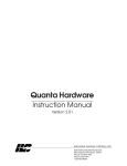
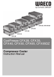
Conditions when reversing from ahead to astern:
When reversing from ahead to astern, the gearing is at first shifted to neutral, the shaft is disengaged
from the engine (1). As the ship continues to move ahead, the propeller is driven like a windmill by the
water streaming against it so that the shaft continues to turn. When the gears are then shifted to
astern, the engine must work against the shaft which is still turning. In an unfavourable case, the
engine might stall.
1 gears
neutral
neutral
Overview
engine
ship
velocity
shaft speed
depends
on ship velocity
astern
2 gears astern
engine
Wiring
ship
veloccity
shaft speed
works
against engine speed
engine speed
To avoid stalling the engine, the control can wait an adjustable time (reversing delay time) before
reversing. The delay time depends on the given lever position of the control head.
The reversing delay time must be determined experimentally during a sea trial. For this, the ship must
st
accelerate from 1 detent ahead to full ahead. The time, the ship needs to reach 2/3 of its maximum
speed, has to be preset as reversing delay time. Afterwards, reversing maneuvers need to be carried
out covering the full speed range.
Adjustment
During the reversing maneuvers, start with a slow speed first and increase gently.
If necessary, the reversing delay time must be adjusted (lengthened, if the engine
revolutions drop too heavily or shortened if no deceleration of the engine speed is
recognisable.
If the reversing delay time is too short, clutch, gearing and engine may be
damaged, if it is too long, the manoeuvrability may be restricted.
!
nominal speed
Operation
1
2
3
4
5
6
7
8
reversing delay time
delay time before clutch
delay time after clutch
reversing delay time
power boost
TIME
idle speed
time
nominal position gears
Error Analysis
ahead
time
astern
TIME reversing delay time
0s
1s
2s
3s
4s
5s
6s
7s
8s
9s
10 s
11 s
12 s
13 s
14 s
15 s
5
Appendix
1
2
3
4
5
6
7
8
For applications with 2 control units, only the portside system must be adjusted.
28
Resetting to default will reset the speed and gearing control values to their
delivery status. This procedure is irreversible.
A reset to default may be done only if the driving engine is turned off. In case of
mechanical controlling, the push-/pull-cables should be disconnected.
1
PARSEL
LED Setup
off
1
2
3
4
Selection default set-up
PARSEL Turn switch to position E.
E
F0 1
2
3
4
5
D
C
B
9 8 7
6
Selection of the system to be reset
Wiring
A
2
PARSEL
for single engines
1
2
3
4
or twin engines: portside system
for twin engines: starboard system
2
PARSEL
1
2
3
4
4
Change to SET-UP-mode
Default position will be reached.
LED set-up will be activated.
5
1
LED Setup
on
PARSEL
1
2
3
4
Storing the default set-up
Change to RUN-mode.
LED set-up will be deactivated.
1
LED Setup
off
Adjustment
3
Overview
Initial condition
Activation of control, command active, lever in neutral
2
Diagram
PARSEL
1
2
3
4
Operation
1
Action
Error Analysis
Step
Appendix
!
General
4.5 Reset to default
29
5 Operation
5.1 General
General
By means of the lever position both,
speed and gear position, (ahead,
neutral, astern) are pre-set.
1. detent
ahead
neutral
1. detent
astern
disengaged
engaged
ahead
engaged
astern
Overview
full
ahead
full
astern
Wiring
Adjustment
The following elements are available as user interfaces:
Keys
• Command transfer
• Acknowledge alarm-buzzer
• Activate special functions
Command lamps
• Indication, if station is active.
Alarm lamps
• Indication, if an error exists.
Lamp synchronizing
• Indication, if synchronizing is active.
key
Command lamp
COMMAND
ALARM
SYNCHRO
lamp
alarm lamps
Operation
In case of twin control heads, the LED for
command and alarm are assigned to the
respective propulsion side.
Error Analysis
In case of several control stations, passive stations must be distinguished from the active one. A
command can always be set only from the active control station. If a passive control station is to set
the command, a change of control station must be carried out before (see chapter 5.3).
On the active control station, the command lamps are on, on the passive station they are off.
active
station
COMMAND
ALARM
passive
station
SYNCHRO
By means of an external switch (see chapter "wiring" - control
head 3.2), the command transfer can be locked. If this is the case,
the alarm lamps at the passive control station will be active.
COMMAND
ALARM
SYNCHRO
COMMAND
ALARM
SYNCHRO
Appendix
30
By a slow flashing of the command lamp, the control head signals that the lever must be moved in
neutral position first. If the levers are already in neutral, the command lamp will flash quickly and the
buzzer sounds at high repetition. The command can be taken over by pressing the key again.
condition
:
lamp test
all lamps
on
all lamps on permanently
COMMAND
ALARM
Overview
After switching on the power supply, all control heads which work correctly are in condition "lamp test"
(all lamps and buzzer on). The command can be requested from every control station by pressing the
key once. After the key has been pressed, the condition "lamp test" will end for all control heads.
On the control head on which the key has been pushed, the command lamps will flash and the buzzer
sound. The lamps flash slowly and the buzzer sounds at slow intervals when the control head lever is
not in neutral position.
General
5.2 Activation and request of control station
SYNCHRO
permanent sound
in neutral
lever in neutral
command lamp flashes slowly
Command lamp flashes quickly
ALARM
SYNCHRO
SYNCHRO
slow bleeping
fast bleeping
lever in neutral
push key
Command lamp on permanently
condition
:
active
station
COMMAND
ALARM
SYNCHRO
As soon as a control station has been activated, gear position neutral and idle speed will be selected.
The command can then be set from the active control station (see chapter 5.1).
Note for control heads twin engine:
In this case, both levers must be moved in neutral. The function of the command lamps is assigned to
the respective lever (port, starboard).
Note for possible error:
If, on a control head, the command lamps do not glow after the activation, it failed to contact the
control unit. Wiring and ID (see chapter 3.2.) need to be controlled. If necessary, the procedure of
entering the control heads into the system (see chapter 4.2) must be repeated.
If there is no functioning control head, the alarm relay will be activated.
Adjustment
COMMAND
ALARM
Operation
COMMAND
Error Analysis
lever not
Appendix
condition
:
requesting
station
Wiring
push key
31
General
5.3 Station transfer
A command transfer is possible in 2 different modes. Which mode is applicable, depends on the
position of switch 3 on the switch board CTRHEAD (see chapter 4.2 control head – comparision of
range / position). Always, the key on the passive control station must be pushed to change the control
station.
Mode "compare direction"
condition:
passive
station
COMMAND
ALARM
SYNCHRO
Overview
push key
condition:
requesting
station
wrong lever position
correct lever position
Command lamp flashes slowly
Command lamp flashes quickly
COMMAND
COMMAND
ALARM
ALARM
SYNCHRO
SYNCHRO
Wiring
slow bleeping
fast bleeping
push key
condition:
active
station
COMMAND
ALARM
SYNCHRO
Adjustment
Command lamp on permanenly
If the lever of the passive control station is placed in a range which is not admissible for command
transfer (the passive lever in astern when the active one is in ahead or neutral or the passive lever in
ahead with the active one in astern or neutral), the buzzer will sound at long intervals and the
command lamps flash at low repetition.
Operation
If the lever of the passive control station is in the correct position for a command transfer (the passive
lever in ahead or neutral when the active lever is in ahead or the passive lever in astern or neutral
while the active one is in astern), the buzzer will sound at short intervals and the command lamps
flash at high repetition. By pressing the key again, the command will be taken over.
Error Analysis
Mode "compare position"
In the mode "compare position", the position of the passive lever may deviate by 30% maximum from
that of the active control head lever. In addition the range (ahead, neutral, astern) must correspond,
before a command transfer can be carried out. It is not necessary to push the key a second time. The
transfer will be executed as soon as the lever positions are correct.
This gives the operator the possibility, after the first actuation of the key, to move the lever until the
correct range is found and the command transfers automatically. If the correct range is not found
within 30 seconds, the command transfer will be stopped.
!
According to the classification rules, the given cruising command must not change
during a command transfer. For this reason, classified ships must choose the
mode "compare position".
Appendix
Note for twin engines:
In case of control heads with two levers, both levers must be placed correctly before the command
can be transferred. The function of the command lamp is assigned to the respective lever. The buzzer
will only sound at short intervals if both lever positions are correct.
5.4 Warming up
By means of the special function "warming up" a determined speed can be set without gear shifting.
This function is necessary to warm up the engines.
To activate "warming up", the key must be pushed at the active control station and, at the same time,
the lever moved in ahead or astern. Then the key may be depressed again. To turn the function off,
the lever must be moved in neutral again. When doing so, the key must not be pushed.
When the function "warming up" is active, the
command lamp flashes.
General
32
Command lamp flashes
ALARM
SYNCHRO
Note for twin engines: The function "warming up" can be activated and deactivated of both sides
separately. The command lamp is assigned to the respective lever.
Overview
COMMAND
To turn this function on and off, the key on the active control station must be pushed. The function can
be switched on in neutral only and switched off at any time.
5.6 Synchronising
If, for twin engine systems, the positions of the port and starboard levers on the active control head
deviate less than 10% from each other in the range of "ahead", the same nominal value (of the port
lever) will be set.
COMMAND
To switch off this function, the key on the active control station must be pushed.
The function will activate again as soon as the levers deviate 10% maximum from each other again at
another position.
Note for „increased idle speed“: "Synchronizing" cannot be switched off if the function "increased idle
speed" is active.
!
The function "Synchronization" is available only if it has been set up before (see
chapter 4.2 "control head", synchronizing).
Operation
ALARM
SYNCHRO
Error Analysis
If "Synchronising" is active, this will be indicated
by the lamp "Synchro".
Appendix
!
The function "increased idle speed" is available only if it has been set up before
(see chapter 4.3. speed). When this function has been entered, "synchronizing"
cannot be deactivated again.
Adjustment
By the special function "increased idle speed" a higher idle speed can be selected. This function will
be necessary if the driving engine shall operate a bow thruster in addition and the normal idle speed
engine performance is not sufficient therefore.
Wiring
5.5 Increased idle speed
33
6 Error analysis
6.1 Errors at the control station
General
Two errors at the control stations must be distinguished:
Alarm
Overview
During an alarm, the setting of the cruising
functions (speed or gearing) is disturbed. On
the active control head, the red alarm lamp will
be on and a buzzer will sound. The buzzer
signal can be acknowledged and thus switched
off by pushing the key.
active station
The command lamps indicate if the control
head is active or passive, i. e. if this station can
set commands or not.
passive station
COMMAND
ALARM
SYNCHRO
COMMAND
ALARM
SYNCHRO
Special case:
special case:
If the active control head is defective, the passive station
passive heads will activate their buzzer and will
Command lamp flashes
go over into the condition "request station".
Wiring
COMMAND
ALARM
SYNCHRO
Warning
Adjustment
In case of a warning, the setting of the cruising
function is not disturbed directly. The red alarm
lamp will be active, but the buzzer will not
sound.
active station
COMMAND
ALARM
SYNCHRO
passive station
COMMAND
ALARM
SYNCHRO
Operation
For twin engines, the alarm and command lamp are assigned to the respective engine side so that
several lamp reactions as described above may combine. The buzzer will be activated as soon as an
alarm is signaled on one of the engine sides.
Error Analysis
Example twin engine
The starboard system is error-free and the
Port
control head is active. The port system is in
Alarm
alarm condition, no active command exists on
Starboard
this control station. Cruising commands can no
No Error
longer be set from this station.
COMMAND
ALARM
SYNCHRO
In case of an alarm, the alarm relay is activated. In addition, idle speed is set and the gears are
disengaged if the remaining function of the system permit it.
Appendix
34
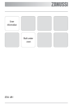
The operation mode of the control is indicated by
2 additional LEDs (RUN, SETUP).
By pressing a key, further error messages can be
displayed.
LED RUN
error
LED SETUP
LED
1
2
3
4
key
Overview
To indicate errors, 4 error LEDs are available
altogether. The top LED is red to facilitate
orientation.
General
6.2 Error indication control unit
LED on in mode "permanent on"
Wiring
It must always be distinguished if the red LED1 flashes or stays on permanently.
LED on in mode "flashing"
Red LED 1 steady light
1
2
3
4
Error type: HARDWARE
1
2
3
4
Error type: PARAMETER
1
2
3
4
Error type: SOFTWARE
Error description: The board of the control unit contains a hardware fault.
Error description: Faulty parameter storage of the control unit.
Error elimination: The parameters of the control must be re-set to default (see chapter
4.5). If afterwards the error is still occuring, the board of the control unit must be replaced.
Operation
Error elimination: Replace board.
Error description: The CAN-controller reports an error.
Error elimination: Control the wiring to the control heads (chapter 3.2). Check the bridges
(see chapter 3.2). There may be a short circuit in the wiring between single veins.
Appendix
Error type: CAN
Error Analysis
Error description: The software of the control unit is defective (e. g. EPROM not plugged).
The board of the control unit must be replaced.
Error elimination: Switch the control on and off. If necessary, replace board of the control
unit.
1
2
3
4
Adjustment
LED off
35
General
1
2
3
4
Error type: ACTUATOR 1
Error description: The system is configurated ( see chapter 2) in such a way that actuator
1 (see chapter 3.3) directs mechanical gear shifting or speed setting. However, the control
states an error in the operation of the actuator.
Error elimination: Check the plugs of actuator 1 for correct connection to the board of the
control unit (see chapter 3.3).
Overview
If necessary, connect actuator 1 to the terminal of actuator 2 on the control unit. If the
actuator works perfectly then, the board of the control unit is defective and must be
replaced. If not, replace the actuator.
1
2
3
4
Error type: ACTUATOR 2
Error description: The system is configurated (see chapter 2) in such a way that actuator
2 (see chapter 3.3) directs mechanical gear shifting or speed setting. However, the control
states an error in the operation of the actuator.
Error elimination: Check the plug of actuator 2 for correct connection to the board of the
control unit (see chapter 3.3).
Wiring
If necessary, connect actuator 2 to the terminal of actuator 2 on the control unit. If the
actuator works perfectly then, the board of the control unit is defective and must be
replaced. If not, replace the actuator.
Adjustment
1
2
3
4
Error type: I/O-CARD 1
Error description: The system (see chapter 2) is configurated in such a way that the I/Oextension board directs electrical gear shifting or speed setting (see chapter 3.4). However,
an error is stated in the activation of I/O-extension board 1.
Error elimination: Check cable between I/O-extension board 1 and the control unit (see
chapter 3.4. electrical throttle control / gear shifting, installation of the I/O-extension board).
If necessary replace cable or I/O-extension board.
Operation
1
2
3
4
Error type: I/O-CARD 2
Error description: The system is configurated (see chapter 2) in such a way that I/Oextension board 2 directs electrical gear shifting or speed setting (see chapter 3.4).
However, an error is stated in the activation of extension board 2.
Error elimination: Check cable between I/O-extension board 2 and 1 or I/O-card 1 and the
control unit (see chapter 3.4 electrical throttle control / gear shifting, installation of the I/Oextension board).
If necessary, replace cable or I/O-board.
Error Analysis
Appendix
36
1
2
3
4
Error type: SYN-CARD (warning only)
Error description: No extension board for synchronizing found.
Error elimination: Check cable from synchronizing board to board of the control unit (see
instructions attached to the synchronizing board).
General
Red LED 1 flashing
1
2
3
4
Error type: SYN-SIG (warning only)
Error description: The synchronizing board cannot measure the speed correctly.
Error elimination: Check cable to the speed sensor (see instructions attached to the
synchronizing board).
Overview
If necessary, replace synchronizing board.
If necessary, replace speed sensor or synchronizing board.
Error type: ACT-CTR
Error description: The control unit reports a total failure of the active control head.
Error elimination: Check cable to the control head (see chapter 3.2). Control the
necessary bridges (see chapter 3.2). Check LED power supply at the control head (see
chapter 3.2). Check ID (see chapter 3.2).
Wiring
1
2
3
4
If necessary, replace control head.
1
2
3
4
Error type: POWER
Error description: The supply voltage (see chapter 3.1) is beyond the admissible range
(for 24V: 18 ... 31,2V, for 12V: 9 ... 15,6 V, if no voltage range has been selected: 9 ...
31,2V).
Error elimination: Charge battery.
1
2
3
4
Error type: TEMPERATURE
Error
description:
(-25 ... +70 °C).
The
temperature
is
beyond
the
admissible
range
Error elimination: The control may only be operated within the admissible temperature
range.
Operation
Error elimination: Replace control head.
Error Analysis
Error description: The hardware of the previous active control head reports an error (e. g.
potentiometer defective).
Adjustment
Error type: ACT-CTR-HW
Appendix
1
2
3
4
37
General
1
2
3
4
Error type: TWIN
Error description: The system was configurated for twin engines – mechanical gear
shifting and speed setting (chapter 2). The communication between the control units port
and starboard does not function.
Error elimination: Check cable between the control units and the necessary bridges (see
chapter 3.2 – special application twin engine with mechanical throttle control / gear
shifting).
Overview
Check power supply of the single control units (LED readiness, see chapter 3.1).
If necessary replace synchronizing board.
1
2
3
4
Error type: SYSCON (warning only)
Error description: The SYSCON switchboard which controls the system configuration (see
chapter 2), was adjusted while the system was active. This is not admissible. It may only be
adjusted in voltage-free condition. Or, the switchboard was turned to a value which was not
admissible.
Wiring
Error elimination: If the SYSCON switchboard was misadjusted, it must be reset correctly
according to chapter 2. If the change was done on purpose, the control must be switched
on and off before the alteration can become effective.
In addition, warnings can be issued. In case of warnings, the red error LED 1 will not be activated.
Furthermore, in case of a warning, the operation mode must be considered.
Adjustment
Mode Initialising (LED RUN and SETUP on)
Operation
1
2
3
4
Error type: TWIN-MASTER
Error description: The SYSCON switchboard is misadjusted for twin engines with
mechanical actuation at the starboard system.
Error elimination: Reset the SYSCON switchboard correctly for twin engines with
mechanical actuation at the starboard system (see chapter 2).
Error Analysis
1
2
3
4
Error type: TWIN-SLAVE
Error description: The SYSCON switchboard is misadjusted for twin engines with
mechanical actuation at the port system.
Error elimination: Reset the SYSCON switchboard for twin engines with mechanical
actuation at the port system (see chapter 2).
Appendix
or
1
2
3
4
Error type: GEAR MASTER
Error description: Gear feedback has been set at the I/O-extension board (see chapter
3.4). The gear feedback is not signalled (for twin engines on the port side). The system
works without gear feedback.
Overview
Mode RUN or SETUP (LED RUN or LED SETUP on)
General
38
Error type: PAS-CTRL
1
2
3
4
Error type: PAS-CTRL-HW
Error description: The control states a total failure of a passive control head.
Error elimination: Check wiring (see chapter 3.2). Check LED power supply at the
defective passive control head. If necessary replace control head.
Error description: The hardware of a passive control head is defective (e. g. potentiometer
error).
Error elimination: Replace defective control head
Error type: GEAR SLAVE
Error Analysis
Error elimination: Check pressure sensor at the gearing. Control LEDs on the I/O
extension board (LED actual ahead or astern or collective feedback). Check wiring.
Operation
Error description: Gear feedback has been set at the I/O-extension board (see chapter
3.4). The gear feedback on the twin engine at the starboard system is not signaled. The
control works without gear feedback.
Appendix
1
2
3
4
Adjustment
1
2
3
4
Wiring
Error elimination: Check pressure sensor at the gearing. Control LEDs on I/O-extension
board (LED actual ahead or astern or collective feedback). Check wiring.
39
General
1
2
3
4
Error type: CTRL-POS
Error description: Before adjusting parameters for speed and gear control, the active
control head must be placed in the correct position (see chapter 4.3 or 4.4). It is not
permitted to adjust the parameter in this lever position.
Error elimination: Change to RUN-mode (step 1 in chapter 4.3 or 4.4). Move lever in
correct position then and repeat the adjustment.
Overview
1
2
3
4
Error type: PROCEDURE
Error description: Parameters were set (chapter 4) in incorrect order (e. g. adjustment of
rotary switch PARSEL in SETUP-mode).
Error elimination: Change to RUN-mode (step 1 in chapter 4.3 or 4.4). Move lever in
correct position then and repeat the adjustment.
1
2
3
4
Error type: ADJUST
Wiring
Error description: It has been tried to set a parameter (chapter 4) that does not exist at all
according to the system configuration (chapter 2) (e. g. rpm starboard for a single engine
system). Or, the rotary switch PARASEL was turned to a value which was not admissible.
Error elimination: Correct setting of switches and rotary switch PARSEL.
Adjustment
Operation
Error Analysis
Appendix
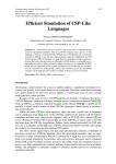
Appendix
1
2
3
4
5
6
7
8
Error Analysis
X12
X5
X4
X3
X11
H1
H2
H3
H4
H5
S4
S1
S5
H7
S6
1
2
3
4
5
6
7
8
X21
X1
X22
X5
X6
S3
X31
fuse
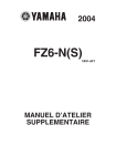
Wiring
LED relay alarm
LED relay start interlock
LED run active
1
2
3
4
CTRHEAD
LED setup active
reversing delay time
delay time after clutch
delay time before clutch
(see chapter 4.4 Gearing)
Adjustment
X40 X41
S2
TIME
H6 H8
Operation
X30
adjustment power supply
(see chapter 3 Wiring 3.1 Power supply)
configuration of system type
(see chapter 2 Overview)
LED error
SYSCON
D
C
B
6
2
3
4
5
1
2
3
4
key setup
RUN / SETUP
port / starboard
direction setup
see chapter 4.2 Control head
9 8 7
F0 1
setting of parameters
see chapter 4.3, 4.4, 4.5
6
2
3
4
5
General
idle speed
rated speed
ahead
astern
power boost
increased idle speed
default
9 8 7
F 0 1
Overview
1
2
4
6
A
B
E
E
D
C
B
A
RUN / control head alignment
off / buzzer on in neutral
compare position / compare range
off / synchronization on
A
E
PARSEL
40
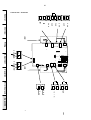
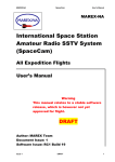
Control Unit – In- and Outputs
41
Control Unit - Terminals
1
CAN
C A N
CAN
CAN
C A N
2
1
2
3
d
a
e
h
Overview
C A N
1
daeh
4
2
General
actuator
X
3 X
4 X
5 X
X
X
1
1
Wiring
3
1
2
0
H
H
H
H
H
1
2
3
4
H
8
5
1 S
5 S
6
H
X
X
3 S
6 X
5 X
X
1 X
40
3
7
1
2
2
1
actuator
1
2
Operation
V c c GND
X4
4 S2 S 6 S
H
X
V c c GND
Adjustment
2
1
2
1
2
1
engine
a l a r m
G N D
V c c
Error Analysis
Appendix
1
start
Rexroth Mecman GmbH
Bartweg 13
D-30453 Hannover
Phone: +49 – 5 11 – 21 36 – 0
Fax: +49 – 5 11 – 21 36 – 2 69
www.boschrexroth.com
Subject to alteration.
This edition supersedes
all previous ones.
Printed in Germany.
No part of this edition may
be repro-duced without
our prior permission.
Order no. 883-890-060-3/2003-07/EN