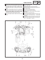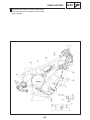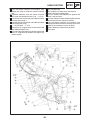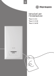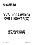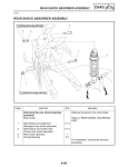
1
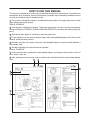
FOREWORD This Supplementary Service Manual has been prepared to introduce new service and data for the YZFR6S/YZF-R6SC. For complete service information procedures it is necessary to use this Supplementary Service Manual together with the following manual. YZF-R6R/YZF-R6SR/YZF-R6RC/YZF-R6SRC SERVICE MANUAL: LIT-11616-16-45 (5SL-28197-10) EAS00001 YZF-R6S/YZF-R6SC SUPPLEMENTARY SERVICE MANUAL 2003 by Yamaha Motor Corporation, U.S.A. First edition, September 2003 All rights reserved. Any reproduction or unauthorized use without the written permission of Yamaha Motor Corporation, U.S.A. is expressly prohibited. Printed in U.S.A. P/N LIT-11616-17-46 EAS00030 NOTICE This manual was produced by the Yamaha Motor Company, Ltd. primarily for use by Yamaha dealers and their qualified mechanics. It is not possible to include all the knowledge of a mechanic in one manual. Therefore, anyone who uses this book to perform maintenance and repairs on Yamaha vehicles should have a basic understanding of mechanics and the techniques to repair these types of vehicles. Repair and maintenance work attempted by anyone without this knowledge is likely to render the vehicle unsafe and unfit for use. This model has been designed and manufactured to perform within certain specifications in regard to performance and emissions. Proper service with the correct tools is necessary to ensure that the vehicle will operate as designed. If there is any question about a service procedure, it is imperative that you contact a Yamaha dealer for any service information changes that apply to this model. This policy is intended to provide the customer with the most satisfaction from his vehicle and to conform to federal environmental quality objectives. Yamaha Motor Company, Ltd. is continually striving to improve all of its models. Modifications and significant changes in specifications or procedures will be forwarded to all authorized Yamaha dealers and will appear in future editions of this manual where applicable. NOTE: S This Service Manual contains information regarding periodic maintenance to the emission control system. Please read this material carefully. S Designs and specifications are subject to change without notice. EAS00040 IMPORTANT MANUAL INFORMATION Particularly important information is distinguished in this manual by the following. The Safety Alert Symbol means ATTENTION! BECOME ALERT! YOUR SAFETY IS INVOLVED! WARNING CAUTION: NOTE: Failure to follow WARNING instructions could result in severe injury or death to the motorcycle operator, a bystander or a person checking or repairing the motorcycle. A CAUTION indicates special precautions that must be taken to avoid damage to the motorcycle. A NOTE provides key information to make procedures easier or clearer. EAS00007 HOW TO USE THIS MANUAL This manual is intended as a handy, easy-to-read reference book for the mechanic. Comprehensive explanations of all installation, removal, disassembly, assembly, repair and check procedures are laid out with the individual steps in sequential order. 1 The manual is divided into chapters. An abbreviation and symbol in the upper right corner of each page indicate the current chapter. Refer to “SYMBOLS”. 2 Each chapter is divided into sections. The current section title is shown at the top of each page, except in Chapter 3 (“PERIODIC CHECKS AND ADJUSTMENTS”), where the sub-section title(s) appears. 3 Sub-section titles appear in smaller print than the section title. 4 To help identify parts and clarify procedure steps, there are exploded diagrams at the start of each removal and disassembly section. 5 Numbers are given in the order of the jobs in the exploded diagram. A circled number indicates a disassembly step. 6 Symbols indicate parts to be lubricated or replaced. Refer to “SYMBOLS”. 7 A job instruction chart accompanies the exploded diagram, providing the order of jobs, names of parts, notes in jobs, etc. 8 Jobs requiring more information (such as special tools and technical data) are described sequentially. 2 1 3 4 5 8 6 7 EAS00008 1 2 GEN INFO SYMBOLS SPEC 3 4 CHK ADJ CHAS 5 6 COOL ENG 7 8 FI ELEC Symbols 10 to 17 indicate the following. 10 9 10 11 12 13 14 15 16 17 TRBL SHTG 11 12 13 14 15 16 17 18 19 20 21 24 The following symbols are not relevant to every vehicle. Symbols 1 to 9 indicate the subject of each chapter. 1 General information 2 Specifications 3 Periodic checks and adjustments 4 Chassis 5 Engine 6 Cooling system 7 Fuel injection system 8 Electrical system 9 Troubleshooting 22 23 25 Serviceable with engine mounted Filling fluid Lubricant Special tool Tightening torque Wear limit, clearance Engine speed Electrical data Symbols 18 to 23 in the exploded diagrams indicate the types of lubricants and lubrication points. 18 19 20 21 22 23 Engine oil Gear oil Molybdenum-disulfide oil Wheel-bearing grease Lithium-soap- based grease Molybdenum-disulfide grease Symbols 24 to 25 in the exploded diagrams indicate the following. 24 Apply locking agent (LOCTITE) 25 Replace the part CONTENTS SPECIFICATIONS GENERAL SPECIFICATIONS . . . . . . . . . . . . . . . . . . . . . . . . . . . . . . . . . . ENGINE SPECIFICATIONS . . . . . . . . . . . . . . . . . . . . . . . . . . . . . . . . . . . . CHASSIS SPECIFICATIONS . . . . . . . . . . . . . . . . . . . . . . . . . . . . . . . . . . . ELECTRICAL SPECIFICATIONS . . . . . . . . . . . . . . . . . . . . . . . . . . . . . . . TIGHTENING TORQUES . . . . . . . . . . . . . . . . . . . . . . . . . . . . . . . . . . . . . . ENGINE TIGHTENING TORQUES . . . . . . . . . . . . . . . . . . . . . . . . . . . CABLE ROUTING . . . . . . . . . . . . . . . . . . . . . . . . . . . . . . . . . . . . . . . . . . . . 1 1 1 1 2 2 3 PERIODIC CHECKS AND ADJUSTMENTS FUEL TANK . . . . . . . . . . . . . . . . . . . . . . . . . . . . . . . . . . . . . . . . . . . . . . . . . . 15 INSTALLING THE FUEL PUMP . . . . . . . . . . . . . . . . . . . . . . . . . . . . . . 16 FUEL INJECTION SYSTEM AIR INDUCTION SYSTEM . . . . . . . . . . . . . . . . . . . . . . . . . . . . . . . . . . . . . 17 AIR INDUCTION SYSTEM DIAGRAMS . . . . . . . . . . . . . . . . . . . . . . . 17 ELECTRICAL ELECTRICAL COMPONENTS . . . . . . . . . . . . . . . . . . . . . . . . . . . . . . . . . . IGNITION SYSTEM . . . . . . . . . . . . . . . . . . . . . . . . . . . . . . . . . . . . . . . . . . . CIRCUIT DIAGRAM . . . . . . . . . . . . . . . . . . . . . . . . . . . . . . . . . . . . . . . . TROUBLESHOOTING . . . . . . . . . . . . . . . . . . . . . . . . . . . . . . . . . . . . . . LIGHTING SYSTEM . . . . . . . . . . . . . . . . . . . . . . . . . . . . . . . . . . . . . . . . . . . CIRCUIT DIAGRAM . . . . . . . . . . . . . . . . . . . . . . . . . . . . . . . . . . . . . . . . CHECKING THE LIGHTING SYSTEM . . . . . . . . . . . . . . . . . . . . . . . . YZF-R6S/YZF-R6SC WIRING DIAGRAM 18 19 19 20 25 25 27 GENERAL SPECIFICATIONS SPEC SPECIFICATIONS GENERAL SPECIFICATIONS Item Model code Standard 5SLD (USA except for CAL) 5SLE (CAL) Limit SSS ENGINE SPECIFICATIONS Item Throttle bodies ID mark Throttle valve size Standard 5SL1 00 (5SLD), 5SL4 10 (5SLE) #100 Limit SSS SSS CHASSIS SPECIFICATIONS Item Front tire Model (manufacturer) Rear tire Model (manufacturer) Standard Limit Pilot SPORT N (MICHELIN) D208 FJ (DUNLOP) SSS Pilot SPORT B (MICHELIN) D208 AJ (DUNLOP) SSS ELECTRICAL SPECIFICATIONS Item Standard Limit Ignition system CDI unit model (manufacturer) F8T816 (MITSUBISHI) SSS Ignition coils Model (manufacturer) Primary coil resistance Secondary coil resistance F6T549 (MITSUBISHI) 0.24 X 0.32 Ω at 20_C (68_F) 5.0 X 6.8 kΩ at 20_C (68_F) SSS SSS SSS –1– TIGHTENING TORQUES SPEC TIGHTENING TORQUES ENGINE TIGHTENING TORQUES Item Oil cooler Cylinder identification sensor Fastener Bolt Bolt Thread Q’ty Q ty size M20 M6 –2– 1 1 Tightening torque Nm mSkg ftSlb 63 6.0 6.3 0.6 46 4.3 Remarks Yamaha bond No.1215 CABLE ROUTING SPEC CABLE ROUTING 1 Right handlebar switch lead 2 Clutch cable 3 Immobilizer unit lead, main switch lead and left han4 5 6 7 8 9 dlebar switch lead Throttle cable (return side) Throttle cable (pull side) Front brake hoses Throttle cables Joint Under bracket A Pass the right handlebar switch lead inside the front brake hoses and over the throttle cables. B Install the throttle cables to the hook so that the pulling side of the throttle cables is routed downward. C Pass the clutch cable through the guide. D Plastic locking tie shall be positioned at 10 mm (0.39 in.) below from the upper bracket. E Clamp the left handlebar switch lead to the front fork with the plastic locking tie and cut the tip of the tie. Clamp it to the protector section. –3– CABLE ROUTING F Pass the horn lead by the outside of the throttle cable and clamp it to the forefront of upper face of the under bracket. Next, route it under the front brake hose and clamp it to the pawl of the under cover. G Clamp it at the position of 40 (1.57 in.) to 60 mm (2.36 in.) from the upper face of the under bracket with the plastic locking tie. Cut the surplus part of the clamp tip leaving 2 (0.08 in.) to 4 mm (0.16 in.). Point the tip of the clamp to the outside of vehicle. H Pass the throttle cables inside the front brake hoses. SPEC I Set in the coupler between the head light’s hollow section and the duct. J Install the relay to the rib of the head light. (Location for the left and right relays is alternative.) K To the wire harness L To the front turn signal light (right) M Set the sub wire harness in the joint. N Do not catch the sub wire harness when the duct is assembled. O To the front turn signal light (left) P Point the tip of the plastic locking tie to the front side of the vehicle. Cut the tip leaving 2 X 10 mm (0.08 X 0.39 in). Q Point the tip of the plastic locking tie under the under bracket and rear side of the vehicle. Cut the tip leaving 2 X 10 mm (0.08 X 0.39 in). –4– CABLE ROUTING 1 2 3 4 5 6 7 8 9 Throttle stop screw Coolant reservoir tank hose Pickup coil lead Rear brake light switch lead Coolant hose Clutch cable Coolant hose protector Hose clamp assembly Hose clamp A Pass the rear brake light switch lead outside of rear engine mount bolt. B Pass the ignition coil lead outside of the radiator hose. C Pass the coolant reservoir tank hose under the frame and right side of the throttle body. SPEC D Pass the clutch cable inside of the coolant reservoir tank hose and radiator return hoses. E Assemble as “ a ” shown below when clamping. F Pass the pickup coil lead over the throttle stop cable. G Tip of the plastic locking tie shall be pointed to the inner side at the rear part of the vehicle. H The punch mark starting point should be lower than the clamp’s top end. However, the aiming position of the punch mark starting point should be 5 mm (0.20 in) below the clamp’s bottom end. I Pass the clutch cable inside of the radiator hose. J Clamp the clutch cable so that it is positioned in this range. K Put and apply the hose clamp to it. –5– CABLE ROUTING L Clamp the clutch cable by routing the upper end of the clamp along with the bottom end of the hose clamp assembly. –6– SPEC CABLE ROUTING 1 2 3 4 5 6 7 8 9 10 11 12 13 14 15 16 17 Throttle cable (return side) Throttle cable (pull side) Starter motor lead Coolant reservoir tank breather hose Bracket 2 Sidestand switch lead Oil level switch lead A.C. magneto lead Radiator fan motor lead Fuel tank breather hose Fuel tank drain hose Coolant reservoir tank cover Drive sprocket cover Coolant reservoir tank Canister hose (for CAL) Canister (for CAL) Balance hose (for CAL) SPEC A Pass the main switch lead under the left handlebar switch lead and then to the right side of the vehicle. B Pass the throttle stop cable by the left side of the side stand switch lead, oil level switch lead, A.C. magneto lead and then to the right side of the vehicle. C Pass the fuel tank drain hose and fuel tank breather hose inside of the reservoir tank breather hose, reservoir tank hose and wire harness and then route it by the out side of the starter motor lead. D Pass the coolant reservoir tank hose outside of the fuel tank drain hose and fuel tank breather hose. E Pass the fuel tank drain hose, fuel tank breather hose through the clamp of the coolant reservoir tank. –7– CABLE ROUTING F Pass the coolant reservoir tank breather hose through the clamp of under the coolant reservoir tank. G Projection allowance from the coolant reservoir tank cover shall be 30 to 50 mm (1.18 X 1.97 in). H Pass the oil level switch lead and sidestand switch lead over the bracket 2. I Pass the oil level switch lead, and sidestand switch lead through the clamp. J 5 X 45 mm (0.20 X 1.77 in). K Clamp the A.C. magneto lead, oil level switch lead and sidestand switch lead. L Pass the side stand switch lead, oil level switch lead and A.C. magneto lead between the engine stay and the engine. M N O P Q R S T U –8– SPEC To the throttle body To the radiator fan motor relay and fuse box Route it above the radiator hose. Pass the throttle cable between the guide of the cover 2 and the frame. Pass the radiator fan motor lead through the hole of the frame to the inner side of the vehicle. Pass the coolant reservoir tank breather hose through the hole of the coolant reservoir tank cover. Order of ups and downs means no object. Route it below the coolant reservoir thank. To the horn CABLE ROUTING 1 2 3 4 5 6 7 8 9 10 Right handlebar switch lead Sub wire harness Head light lead Meter lead Cover 8 Ignition coil lead Throttle position sensor coupler Coolant reservoir tank hose Throttle stop cable Speed sensor lead coupler 11 Crankshaft position sensor lead 12 13 14 15 16 17 coupler Fuel tank breather hose (except for CAL) Fuel tank drain hose (except for CAL) Fuel hose (return side, except for CAL) Fuel pump 2 coupler Fuel pump 1 coupler Starter motor lead –9– SPEC 18 Fuel hose (feed side, except for 19 20 21 22 23 24 25 26 27 CAL) Crankcase breather hose Air vent hose Fuse box Cover 7 Radiator fan motor relay Radiator fan motor lead Left handlebar switch lead Main switch lead Wire harness CABLE ROUTING 28 Throttle cables 29 Throttle sub-lead 1 (white 6 32 Sidestand switch lead coupler (blue 2 poles) poles) 33 A.C. magneto lead coupler 30 Throttle sub-lead 2 (black 6 (white 3 poles) poles) 34 Rear brake light switch lead cou31 Oil level switch lead coupler pler (brown 2 poles) (white 1 pole) –10– 35 Neutral 36 37 38 39 SPEC switch lead coupler (connector 1 pole) Fuel hose (return side, for CAL) Fuel hose (feed side, for CAL) Fuel tank drain hose (for CAL) Canister hose (for CAL) CABLE ROUTING A To the headlight B Make sure not to drop the headlight sub wire harness beneath the projection of the duct. Check it when installing the side cowling. C Clamp the plastic locking tie to the cover 8. Place the coupler at the rear side of the vehicle against the plastic locking tie. Point the tip of the plastic locking tie to the downward in the inner side of the vehicle. D Route the head light and meter leads under the frame’s lower part from the hollow section of the cover 2. E Pass the left and right handlebar switch leads outside of the air filter case air vent hose. SPEC F Connect the couplers (4 units) at the frame side hole. Do not catch each lead and wire harness when the cover 8 is attached. G From the radiator H Pass the coolant reservoir tank hose through forward the starter motor lead and speed sensor lead. I Pass the speed sensor lead coupler and crankshaft position sensor lead coupler over the throttle stop cable. J Pass the fuel tank breather hose and fuel tank drain hose over the fuel hose and fuel return hose. One rotation is possible for a twist of fuel tank breather hose and fuel tank drain hose before an engine clamp. K To the rear brake light switch lead. –11– CABLE ROUTING L To the neutral switch M Insert the wire harness wrapping clamp to the frame hole. N Pass the battery negative lead over the wire harness. O There should be no interference between the wire harness and the tip of the rear frame attaching bolts. P To the coolant reservoir tank Q To the intake air temperature sensor (air filter case) R To the oil level switch, sidestand switch and A.C. magneto S Install the wire harness wrapping clamp to the stay of the throttle body. T Pass the wire harness over the throttle air vent hose. SPEC U Pass the wire harness between frame and coolant hose. V Pass it through the frame hole. W Do not catch the coupler when the air filter case is assembled. X Clamp the wire harness, left and right handlebar switch leads and main switch lead. Align the tapping positions of three leads except the wire harness. Point the tip of the clamp to the front side of the vehicle. Y Sealing set of the cover can be either upper or lower against the frame lower end. However, it should not be caught. Z Clamp the wire harness, main switch lead branch section and radiator fan motor lead. –12– CABLE ROUTING AA Branching leads to the fuse box and radiator fan motor relay shall pass through the guide section of the cover 2 under the wire harness and then to the outside of the frame. AB To the fuse box and fan motor relay AC Pass the throttle cables over the cover 2. AD Point the tip of the plastic locking tie to the rear side of the vehicle. AE To the main switch lead coupler SPEC AF Tip of the plastic locking tie should point to the downward outside of the vehicle. AG Use the plastic locking tie to clamp the starter motor lead at the protector section. AH Branching harness from the wire harness. AI Poss the canister hose over fuel return hose and under the fuel hose. AJ Insert until it sets. AK The clamp by the side of a hose comes below an attachment clamp. –13– CABLE ROUTING Fuel pump assembly Fuel tank drain hose Fuel tank breather hose (except for CAL) Clamp Clip Canister (for CAL) Blance hose (for CAL) Canister hose (for CAL) A Install the O-ring with its lip pointed upward. B Pass the fuel tank drain hose and fuel tank breather hose through the clamp. There needs to be no crookedness in fuel tank drain hose and fuel tank breather hose between fuel tank’s nipple and clamp. 1 2 3 4 5 6 7 8 SPEC C Direction of which is sufficient as the knob of a clip. D Air opening E Install the breather hose without projecting canister nipple out of the breather hose. F Install the clip with its tab pointed in the downward direction. G Install the clip with its tab pointed in the upward direction. H Install the roll over valve until it contacts with the fuel tank’s nipple. I To injector –14– FUEL TANK CHK ADJ EAS00040 PERIODIC CHECKS AND ADJUSTMENTS FUEL TANK 7 Nm (0.7 mSkg, 5.1 ftSlb) 7 Nm (0.7 mSkg, 5.1 ftSlb) 4 Nm (0.4 mSkg, 2.9 ftSlb) Order 1 2 3 4 5 6 7 8 9 10 Job/Part Removing the fuel tank Rider seat Fuel hose connector cover Fuel hose Fuel return hose Fuel sender coupler Fuel pump coupler Clamp Fuel tank overflow hose Fuel tank breather hose Fuel tank Fuel pump Q’ty Remarks Remove the parts in the order listed. Refer to “SEATS”. 1 1 1 1 1 1 1 1 1 1 Disconnect. Disconnect. For installation, reverse the removal procedure. Refer to the CABLE ROUTING for how to attach a hose. –15– FUEL TANK CHK ADJ INSTALLING THE FUEL PUMP 1. Install: S fuel pump 4 Nm (0.4 mSkg, 2.9 ftSlb) NOTE: S Do not damage the installation surfaces of the fuel tank when installing the fuel pump. S Always use a new fuel pump gasket. S Install the fuel pump as shown in the illustration. S Tighten the fuel pump bolts in stages in a crisscross pattern and to the specified torque. –16– AIR INDUCTION SYSTEM FUEL INJECTION SYSTEM AIR INDUCTION SYSTEM EAS00509 AIR INDUCTION SYSTEM DIAGRAMS 1 Air cut-off valve 2 Reed valve 3 To air filter case A To cylinder #1 and #2 B To cylinder #3 and #4 –17– FI ELECTRICAL COMPONENTS ELEC ELECTRICAL ELECTRICAL COMPONENTS 1 2 3 4 5 6 7 8 Coolant temperature sensor Intake air temperature sensor Intake air pressure sensor Lean angle cut-off switch Atmospheric pressure sensor ECU Starting circuit cut-off relay Turn signal relay 9 10 11 12 13 14 –18– Speed sensor Crankshaft position sensor Cylinder identification sensor Radiator fan motor relay Headlight relay (on / off) Headlight relay (dimmer) ON OFF 1 W R W W W W W L/B - L/Y L/B L/B L/Y 10 R Br/L R Br/L Br/L R W W W B 3 R/W R 4 R Br/L Br/L 48 47 46 B R/W L BrG G/Y 49 BrG R/Y Br L/B B/L R/Y R B L B L 50 Y B/L B YW B/Y 52 51 B Br Y B B 5 R R B B B L/W R/W 53 B B 67 Y - Br/WR/Y R G/Y B Y L/R Ch L/Y B B/Y Br Dg Y Br B R/B L 6 R R/B B Br 42 R R L/WR/W R/W L/W G/Y 8 R G/Y L/W R/W 7 R R B L/Y W W 9 66 43 54 Y Dg B 187 55 B B/Y B B/Y H B/Y B/L C B/L RUN OFF 44 Br B/Y B L/Y Ch R/Y Br/W - R 65 ON 57 OFF L/W LO B R/Y HI 56 PUSH FREE 45 L/W R/W Br/L W R/Y A R/Y L/B R/Y B/L R/W B/Y B B/L B 59 R/B B/Y W L/W B W L/W B/W W R/W G/Y BrG L L Br Y Y R/B 187 R/G Ignition coil Spark plug Neutral switch Crankshaft position sensor Lean angle cut-off switch Engine stop switch Clutch switch B B Y Y A Y YW B/L B/Y YW A YW Y B B L Ch B Ch 64 L Br L 12 60 R L/W G/R W 35 33 Y/B B/R - 32 31 30 13 37 36 34 B/W B B/W Y/L B Y/L Y/L B/W Y/B B Y/B Sb/W A Sb/W Y/B Sb/W B Gy/G O/G O/G Gy/G B L B Y B/L Y L 24 23 L B L Dg B Dg 63 Dg A Dg B B Ch Ch - B B Dg Dg - Dg L Ch Dg B/Y Sb/W - G/W Br - Y/L - B/W R/G 40 40 39 39 38 - - - 28 B/L B/L E B/L L W/B B/L B/L L E L W/B E W/B L Y/G B/L B/L B P L B/L Y/G B/L L - B/L G B/L - - B/R Y/B B/WR/G Y/L HEADLIGHT SUB WIRE HARNESS B W L/Y B/L G/W B/L Br/W B/L B/L 22 21 L W/Y B/L B/L - Sb G/W Br/W Sb - 27 Y W/B L B/L Gy L/Y B/Y Y/B R/L Lg L/W R/W W/Y P Y/G P/W G P/W P/W G/W G G/W G/W Br/W G Br/W Br/W Y G Y 19 L - R/B G/B L/B O/B Y/B B O/G Gy/G - B/L YW Lg G/W Gy Y/R R/L Y/R Br/R B O Gy/R WIRE HARNESS Y/B W Y/L R/G B/W Y W/Y P P/W R/W Br/W B/W W/B - - L/B G/Y Y/G B/Y W Y/L - - L/W - L F L 25 B Gy 20 W L/Y 26 C WIRE HARNESS Headlight coupler B B/L W/B L P B/L L P/W B/L L B/L Y L Gy B/L WIRE HARNESS SUB-WIRE HARNESS 1 Gy/R O R/B D R/B O Gy/R P/W 61 G/W Ch B/R W B B/R R/G Br G/W A G/W R/G B R/G R/W A Br 29 R/L B G/W B L B/L B/L L WIRE HARNESS SUB-WIRE HARNESS 2 W/B Br/R E Br/R W/B L 62 W 41 R/L B/Y Sb/W R/B L/W B/W B/R L/W Lg R/W L/B L/Y Sb L O/B L/B WIRE HARNESS SUB-WIRE HARNESS 3 L/B O/B L G/B R/B R/L B/L L L/B B 11 - P/W B/L F N R R B B Br/W 58 Ch A Ch L/Y R/L R/B G/B B/Y G/W Br/W Y L B/L P/W - W 2 B Sb/W B L/B L/B B WIRE HARNESS SUB-WIRE HARNESS 4 Ch B L/R B Br B R/L B Sb Ch B L/R Br/W Br/W G/W B WIRE HARNESS Headlight coupler Dg Lg Ch L Br L/R B L/Y B/Y B B/L B B C B 187 B H B Dg Sb Sb Sb G 14 WIRE HARNESS O G/Y Y/L Y/R Y/R Br/R O/B L/B F O/B G/B Br/R R/L O/B O/B R/L L/B L/B R/L G/B Br/RR/B Br/R E Br/R O/B L/B F L/B G/B F G/B G/B R/L R/B R/B B R/B F R/B Gy/G B O/G B D B D O/G B Gy/R B O Gy/G D Gy/G O/G Gy/R D Gy/R D O R/B YW Gy/G O/G Gy/R O 17 17 17 17 Br Br/R 16 16 16 16 18 R/L R/L R/L R/L 15 15 15 15 R/B B Gy/G B O/G B Gy/R B O HEADLIGHT SUB WIRE HARNESS - Ch G/W Y R/Y Sb/W Dg B Y/W Br R/W Y/W B Dg Sb/W A R/Y Y G/W Ch - B Y Br/W G/W B B/Y B W H B/W B B/Y L R/L Dg B 16 17 20 21 29 47 59 B Main switch Battery Fuse (main) Fuse (ignition) Starting circuit cut-off relay Sidestand switch ECU B Gy B/L –19– B/L 1 5 6 11 12 13 15 W/Y 187 B A B IGNITION SYSTEM ELEC EAS00735 IGNITION SYSTEM CIRCUIT DIAGRAM R/B D R/B R/L F R/L IGNITION SYSTEM EAS00737 ELEC EAS00739 TROUBLESHOOTING 2. Battery S Check the condition of the battery. Refer to “CHECKING AND CHARGING THE BATTERY” in chapter 3. The ignition system fails to operate (no spark or intermittent spark). Check: 1. Main and ignition fuses 2. Battery 3. Spark plugs 4. Ignition spark gap 5. Ignition coil resistance 6. Crankshaft position sensor 7. Main switch 8. Engine stop switch 9. Neutral switch 10. Sidestand switch 11. Clutch switch 12. Starting circuit cut-off relay 13. Lean angle cut-off switch 14. Wiring connections (of the entire ignition system) Minimum open-circuit voltage 12.8 V or more at 20_C (68_F) S Is the battery OK? YES NO S Clean the battery terminals. S Recharge or replace the battery. EAS00741 NOTE: S Before troubleshooting, remove the following part(s): 1. seat 2. fuel tank 3. air filter case 4. bottom cowling 5. side cowlings S Troubleshoot with the following special tool(s). 3. Spark plugs The following procedure applies to all of the spark plugs. S Check the condition of the spark plug. S Check the spark plug type. S Measure the spark plug gap. Refer to “CHECKING THE SPARK PLUGS” in chapter 3. Standard spark plug CR9EK or CR10EK (NGK) Spark plug gap 0.6 X 0.7 mm (0.0236 X 0.0276 in) Dynamic spark tester YM-34487 Ignition checker 90890-06754 Pocket tester 90890-03112, YU-3112 S Is the spark plug in good condition, is it of the correct type, and is its gap within specification? YES EAS00738 NO 1. Main and ignition fuses S Check the main and ignition fuses for continuity. Refer to “CHECKING THE FUSES” in chapter 3. S Are the main and ignition fuses OK? YES Re-gap or replace the spark plug. NO Replace the fuse(s). –20– IGNITION SYSTEM ELEC EAS00743 4. Ignition spark gap The following procedure applies to all of the spark plugs. S Disconnect the spark plug cap from the spark plug. S Connect the ignition checker 1 and ignition coil 2 as shown. S Set the main switch to “ON”. S Measure the ignition spark gap a . S Crank the engine by pushing the starter switch and gradually increase the spark gap until a misfire occurs. S Measure the primary coil resistance. Primary coil resistance 0.24 X 0.32 Ω at 20_C (68_F) S Connect the pocket tester (Ω ignition coil as shown. 1k) to the Negative tester probe ! ignition coil terminal 1 Positive tester probe ! spark plug terminal 2 Minimum ignition spark gap 6 mm (0.24 in) S Is there a spark and is the spark gap within specification? NO YES S Measure the secondary coil resistance. Secondary coil resistance 5.0 X 6.8 kΩ at 20_C (68_F) The ignition system is OK. S Is the ignition coil OK? YES NO EAS00747 5. Ignition coil resistance Replace the ignition coil. The following procedure applies to all of the ignition coils. S Disconnect the ignition coil leads from the wire harness. S Connect the pocket tester (Ω 1) to the ignition coil as shown. Positive tester probe ! ignition coil terminal Negative tester probe ! ignition coil terminal –21– IGNITION SYSTEM EAS00748 ELEC EAS00750 6. Crankshaft position sensor resistance 8. Engine stop switch S Disconnect the crankshaft position sensor coupler from the wire harness. S Connect the pocket tester (Ω 100) to the crankshaft position sensor coupler as shown. S Check the engine stop switch for continuity. Refer to “CHECKING THE SWITCHES”. S Is the engine stop switch OK? YES Positive tester probe ! gray 1 Negative tester probe ! black 2 NO Replace the right handlebar switch. EAS00751 9. Neutral switch S Check the neutral switch for continuity. Refer to “CHECKING THE SWITCHES”. S Is the neutral switch OK? S Measure the crankshaft position sensor resistance. YES Crankshaft position sensor resistance 248 X 372Ω at 20_C (68_F) (between gray and black) NO Replace the neutral switch. S Is the crankshaft position sensor OK? EAS00752 10. Sidestand switch YES NO S Check the sidestand switch for continuity. Refer to “CHECKING THE SWITCHES”. S Is the sidestand switch OK? Replace the crankshaft position sensor. YES Replace the sidestand switch. EAS00749 7. Main switch S Check the main switch for continuity. Refer to “CHECKING THE SWITCHES”. S Is the main switch OK? YES NO EAS00763 11. Clutch switch S Check the clutch switch for continuity. Refer to “CHECKING THE SWITCHES”. S Is the clutch switch OK? NO Replace the main switch. YES NO Replace the clutch switch. –22– IGNITION SYSTEM ELEC EAS00753 12. Starting circuit cut-off relay NOTE: When you switch the positive and negative tester probes, the readings in the above chart will be reversed. S Disconnect the starting circuit cut-off relay coupler from the wire harness. S Connect the pocket tester (Ω 1) to the starting circuit cut-off relay coupler as shown. S Check the starting circuit cut-off relay for continuity. S Are the tester readings correct? YES Positive tester probe ! sky blue 1 Negative tester probe ! black/yellow 2 Positive tester probe ! sky blue 1 Negative tester probe ! blue/yellow 3 Replace the starting circuit cut-off relay. 13. Lean angle cut-off switch voltage Continuity S Remove the lean angle cut-off switch. S Connect the pocket tester (Ω 1) to the lean angle cut-off switch terminals as shown. Positive tester probe ! blue/black 4 Negative tester probe ! black/yellow 2 Positive tester probe ! blue Negative tester probe ! yellow/green Positive tester probe ! black/yellow 2 Negative tester probe ! sky blue 1 Positive tester probe ! blue/yellow 3 Negative tester probe ! sky blue 1 NO No continuity Positive tester probe ! blue/yellow 3 Negative tester probe ! blue/black 4 Lean angle cut-off switch voltage Less than 65_ a ! Approximately 1 V More than 65_ b ! Approximately 4 V S Is the lean angle cut-off switch OK? –23– IGNITION SYSTEM YES NO Replace the lean angle cut-off switch. EAS00754 14. Wiring S Check the entire ignition system’s wiring. Refer to “CIRCUIT DIAGRAM”. S Is the ignition system’s wiring properly connected and without defects? YES Replace the ignitor unit. NO Properly connect or repair the ignition system’s wiring. –24– ELEC ON OFF 1 W R W W W W W L/B R Br/L Br/L R L G/Y B L BrG L R/W B 48 47 10 L/Y L/B L/B L/Y Br/L R Br/L R Br/L 46 - W W W B 3 B 49 BrG R/Y Br 50 R/W R Y L/B B/Y B/L B/L R/Y 4 R B YW R/G 52 51 B Br Y B B 5 R R B B B L/W R/W 53 B B 67 Y - Br/WR/Y R G/Y B Y L/R Ch L/Y B B/Y Br Dg Y Br B R/B L 6 R R/B B Br 42 R R L/WR/W R/W L/W G/Y 8 R G/Y L/W R/W 7 R R B L/Y W R/W G/Y 9 66 43 54 Y Dg B 187 55 B B/Y B B/Y H B/Y B/L C B/L RUN OFF 44 Br B/Y B L/Y Ch R/Y Br/W - R R/W B/Y L/W 65 LO HI 56 PUSH FREE 45 B R/Y B B/L B L/W R/W W R/B 187 ON OFF 57 59 R/B B/Y Br/L W L/W B W L/W B/W W L/B YW BrG L L B Br Y Y R/Y A R/Y R/Y B/L B/L B/Y YW A YW Y B B Y Y A Y Br B B L/R B B L Ch B Ch 64 L Br L N R R 60 B L Dg B L L/B B 11 Dg 63 Dg A Dg 12 B B Br/W 58 Ch A Ch L/Y L L/W G/R B B Ch Ch - 62 W 41 W R/L B B Dg Dg - 61 G/W Dg Ch B/R W B B/R R/G Br 29 G/W A G/W R/G B R/G R/W A Br F L O/B L/B G/B R/B R/L 35 33 34 40 40 39 39 38 37 36 L B/L B/L L L Ch Dg B/Y Sb/W - G/W Br B/W B B/W Y/L B Y/L Y/L B/W Y/B B Y/B Sb/W A Sb/W Y/B Sb/W WIRE HARNESS SUB-WIRE HARNESS 2 W/B Br/R E Br/R W/B - Y/L - B/W R/G 13 Y/B B/R - 32 31 30 R/L B G/W B WIRE HARNESS SUB-WIRE HARNESS 3 B/Y Sb/W R/B L/W B/W B/R L/W Lg R/W L/B L/Y Sb R WIRE HARNESS SUB-WIRE HARNESS 4 L/B O/B L B/Y - P/W B/L R/L R/B G/B L B/L P/W - W W B Sb/W B L/B L/B B Sb Ch B L/R Br/W Br/W Lg Ch L R/L B 2 Dg R/L Dg B G/W B WIRE HARNESS Headlight coupler Ch B Br L/R B L/Y B/Y B B/L B B C B 187 B H B Dg B B Gy/G O/G O/G Gy/G B L B Y B/L Y L - - 28 B/L B/L E B/L L W/B B/L L E L P L B/L Y/G B/L L L F L 25 B Gy 20 B/L - B/L B - B/L G B/L - - B/R Y/B B/WR/G Y/L - R/B G/B L/B O/B Y/B B O/G Gy/G HEADLIGHT SUB WIRE HARNESS B W L/Y B/L G/W B/L Br/W B/L B/L 22 21 L W/Y B/L B/L - Sb 27 W/Y P Y/G P/W G P/W P/W G/W G G/W G/W G/W Y W/B L B/L Gy Br/W G Br/W Br/W Y G Y 19 L/Y B/Y Y/B R/L Lg L/W R/W Br/W Sb - - B/L YW Lg G/W Gy Y/R R/L Y/R Br/R B O Gy/R L WIRE HARNESS Y/B W Y/L R/G B/W Y W/Y P P/W R/W Br/W B/W W/B - - L/B G/Y Y/G B/Y W Y/L - W/B E W/B L Y/G B/L C - L/W - W/B L P B/L L P/W B/L L P/W Y L B/L B B/L WIRE HARNESS Headlight coupler W L/Y 26 24 L B/L 23 Gy B/L WIRE HARNESS SUB-WIRE HARNESS 1 Gy/R O R/B D R/B O Gy/R Gy B/L Sb Sb Sb G/W Br/W Y L G 14 WIRE HARNESS O G/Y Y/L Y/R Y/R Br/R O/B L/B F O/B G/B Br/R R/L O/B O/B R/L L/B L/B R/L G/B Br/RR/B Br/R E Br/R O/B L/B F L/B G/B F G/B G/B R/L R/B R/B B R/B F R/B Gy/G B O/G B D B D O/G B Gy/R B O Gy/G D Gy/G O/G Gy/R D Gy/R D O R/B YW Gy/G O/G Gy/R O 17 17 17 17 Br Br/R 16 16 16 16 18 R/L R/L R/L R/L 15 15 15 15 R/B B Gy/G B O/G B Gy/R B O HEADLIGHT SUB WIRE HARNESS - Ch G/W Y R/Y Sb/W Dg B Y/W Br R/W Y/W B Dg Sb/W A R/Y Y G/W Ch - B Y Br/W G/W W B/Y B B H B/W B B/Y B/L –25– W/Y 187 B A B LIGHTING SYSTEM ELEC EAS00780 LIGHTING SYSTEM CIRCUIT DIAGRAM R/B D R/B R/L F R/L LIGHTING SYSTEM 1 5 6 15 40 42 50 54 55 56 60 61 71 72 73 Main switch Battery Fuse (main) ECU High beam indicator light Meter light Fuse (headlight) Headlight relay (on / off) Headlight relay (dimmer) Fuse (park) Pass switch Dimmer switch Headlight License light Tail/ brake light –26– ELEC LIGHTING SYSTEM ELEC EAS00788 Headlight Positive tester probe ! black/yellow 3 Negative tester probe ! black 4 CHECKING THE LIGHTING SYSTEM 1. The headlight and the high beam indicator light fail to come on. B High beam 1. Headlight bulb and socket S Check the headlight bulb and socket for continuity. Refer to “CHECKING THE BULBS AND BULB SOCKETS” S Are the headlight bulb and socket OK? YES NO Replace the headlight bulb, socket or both. High beam indicator light (LEDs) Positive tester probe ! black/yellow 5 Negative tester probe ! black/white 6 Meter assembly coupler (wire harness side) 2. Voltage S Connect the pocket tester (DC 20 V) to the headlight and meter assembly couplers as shown. A When the dimmer switch is set to “ B When the dimmer switch is set to “ ” ” Headlight Positive tester probe ! black/blue 1 Negative tester probe ! black 2 S Turn the main switch to “ON”. S Start the engine. S Set the dimmer switch to “ ” or “ ”. S Measure the voltage (DC 12 V) of black/blue 1 or black/yellow 3 on the headlight coupler (wire harness side). S Is the voltage within specification? Headlight coupler (wire harness side) A Low beam YES This circuit is OK. –27– NO The wiring circuit from the main switch to the headlight coupler is faulty and must be repaired. ELEC LIGHTING SYSTEM EAS00789 EAS00790 2. The meter light fails to come on. 3. The tail/brake light fails to come on. 1. Meter light (LEDs) 1. Tail/brake light (LEDs) S Check the meter light for continuity. Refer to “CHECKING THE LEDs” S Are the meter light OK? S Check the tail/brake light for continuity. Refer to “CHECKING THE LEDs” S Are the tail/brake light OK? YES NO YES Replace the meter assembly. NO Replace the tail/brake light assembly. 2. Voltage 2. Voltage S Connect the pocket tester (DC 20 V) to the meter assembly coupler (wire harness side) as shown. S Connect the pocket tester (DC 20 V) to the tail/brake light coupler (wire harness side) as shown. Positive tester probe ! blue 1 Negative tester probe ! black/white 2 Positive tester probe ! blue/red 1 Negative tester probe ! black 2 S Turn the main switch to “ON”. S Measure the voltage (DC 12 V) of blue 1 on the meter assembly coupler (wire harness side). S Is the voltage within specification? S Turn the main switch to “ON”. S Measure the voltage (DC 12 V) of blue/red 1 on the tail/brake light coupler (wire harness side). S Is the voltage within specification? YES This circuit is OK. NO YES The wiring circuit from the main switch to the meter assembly coupler is faulty and must be repaired. This circuit is OK. –28– NO Wiring circuit from the main switch to the tail/brake light coupler is faulty and must be repaired. LIGHTING SYSTEM EAS00792 4. The license light fails to come on. 1. License light bulb and socket S Check the license light bulb and socket for continuity. Refer to “CHECKING THE BULBS AND BULB SOCKETS” S Are the license light bulb and socket OK? YES NO Replace the license light bulb, socket or both. 2. Voltage S Connect the pocket tester (DC 20 V) to the license light coupler (wire harness light side) as shown. Positive tester probe ! blue/red 1 Negative tester probe ! black 2 S Turn the main switch to “ON”. S Measure the voltage (DC 12 V) of blue/red 1 on the license light coupler (wire harness side). S Is the voltage within specification? YES This circuit is OK. NO The wiring circuit from the main switch to the license light coupler is faulty and must be repaired. –29– ELEC YZF-R6S/YZF-R6SC WIRING DIAGRAM YZF-R6S/YZF-R6SC WIRING DIAGRAM 1 2 3 4 5 6 7 8 9 10 11 12 13 14 15 16 17 18 19 20 21 22 23 24 25 26 27 28 29 30 31 32 33 34 35 36 37 38 39 40 41 42 43 44 45 46 47 48 49 50 51 52 53 54 55 56 57 58 59 60 Main switch A.C. magneto Rectifier/ regulator Fuse (backup) Battery Fuse (main) Starter relay Starter motor Fuse (fuel injection) Fuse (ignition) Starting circuit cut-off relay Sidestand switch Fuel pump ECU Ignition coil Spark plug Fuel injector Air induction system solenoid Neutral switch Crankshaft position sensor Intake air temperature sensor Coolant temperature sensor Throttle position sensor Intake air pressure sensor Atmospheric pressure sensor Cylinder identification sensor Speed sensor Lean angle cut-off switch Meter assembly Fuel level warning light Oil level warning light Neutral indicator light Tachometer Shift timing indicator light Multi-function meter Engine trouble warning light Coolant temperature indicator light High beam indicator light Turn signal indicator light Meter light Oil level switch Right handlebar switch Front brake light switch Engine stop switch Start switch Fuse (signal) Fuse (headlight) Fuse (radiator fan motor) Radiator fan motor relay Radiator fan motor Headlight relay (on / off) Headlight relay (dimmer) Rear brake light switch Left handlebar switch Clutch switch Dimmer switch Horn switch Turn signal switch Horn Turn signal relay 61 62 63 64 65 66 67 Rear turn signal light (right) Rear turn signal light (left) Front turn signal / position light (right) Front turn signal / position light (left) Headlight License light Tail/ brake light COLOR CODE B ....... Br . . . . . . Ch . . . . . Dg . . . . . G ...... Gy . . . . . L ....... Lg . . . . . . O ...... P ....... R....... Sb . . . . . . W ...... Y ....... B/ L . . . . . B/ R . . . . B/ W . . . . B/ Y . . . . Br/ G . . . Br/ L . . . . Br/ R . . . . Br/ W . . . Br/ Y . . . . G/B . . . . G/W . . . . G/Y . . . . Gy/ G . . . Gy/ R . . . L/B . . . . . L/R . . . . L/W . . . . L/Y . . . . . O/B . . . . O/G . . . . P/ W . . . . R/ B . . . . R/ G . . . . R/ L . . . . R/ W . . . . R/ Y . . . . Sb/ W . . . W/ B . . . . W/ Y . . . . Y/ B . . . . Y/ G . . . . Y/ L . . . . . Y/ W . . . . Black Brown Chocolate Dark green Green Gray Blue Light green Orange Pink Red Sky blue White Yellow Black/ Blue Black/ Red Black/ White Black/ Yellow Brown/ Green Brown/ Blue Brown/ Red Brown/ White Brown/ Yellow Green / Black Green / White Green / Yellow Gray / Green Gray / Red Blue/ Black Blue/ Red Blue/ White Blue/ Yellow Orange / Black Orange / Green Pink/ White Red/ Black Red/ Green Red/ Blue Red White Red/ Yellow Sky blue / White White/ Black White/ Yellow Yellow/ Black Yellow/ Green Yellow/ Blue Yellow/ White