1
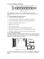
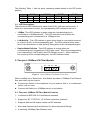
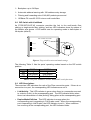
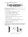
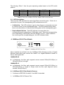
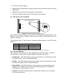
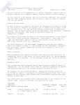
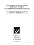
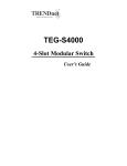
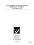
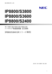
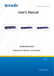
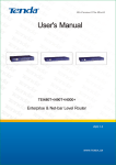
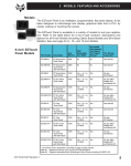
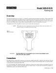
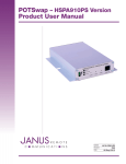
User’s Manual
MIL-S2612, 2-port 100BASE-FX Module (ST)
MIL-S2613, 2-port 100BASE-FX Module (SC)
MIL-S2614, 2-port 100BASE-FX Module (MT-RJ)
MIL-S2615, 2-port 100BASE-FX Module (VF-45)
MIL-S2622, 4-port 100BASE-FX Module (ST)
MIL-S2623, 4-port 100BASE-FX Module (SC)
MIL-S2624, 4-port 100BASE-FX Module (MT-RJ)
MIL-S2625, 4-port 100BASE-FX Module (VF-45)
MIL-S3630, 8-port 10/100BASE-TX Module (RJ-45)
MIL-S6603SX, 1-port 1000BASE-SX Module (SC)
MIL-S6603LX, 1-port 1000BASE-LX Module (SC)
1. 8 ports 10/100Base-TX Module
100
LK/ACT
FD/COL
MIL-S3630
1
2
3
4
5
6
7
8
Figure 1. Front Panel
When installed into a Switch hub, the 10/100Base-TX Module provides 8
10/100Mbps Switch ports which can connect to 10Mbps or 100Mbps hub or end
station.
1-1. 8 Ports 10/100Base-Tx Module Features
! 8 10/100Base-TX N-Way Switch ports.
! Conforms to IEEE 802.3, IEEE 802.3u and IEEE 802.3x standards
! Store and forward switch architecture for abnormal packet filtering
! Support for half and full duplex on all ports
! Backplane up to 2.4Gbps
! 2M memory Buffer support
! Automatic address learning with 12K address entry storage
! Filtering and forwarding rate of 14,880~148,800 packets per second
! DIP Switch for decision connection mode with other network devices
1-2. DIP Switch with Link Mode
The 8 port 10/100Base-TX module provides dip switch for 1 to 4 port to adjust link
mode with other network devices. Another 4 ports use auto-negotiation protocol
only. There are three type of link mode can be chosen, Auto-negotiation,
100Mbps/Full duplex and 10Mbps/Full duplex.
P ort 1
P ort 2
P ort 3
P ort 4
P ort 5
ON
adjustable
D IP S w itch for
ports
P ort 1 to P ort 4
P ort 1
P ort 3
1 2 3 4 5 6 7 8
P ort 2
P ort 6
P ort 4
O FF
P ort 7
P ort 8
Full D uplex
A utonegotiation
10M
1 2
100M
Figure 2. Dip switch location and mode settings
If you adjust to auto-negotiation, then the DIP for 100Mbps and 10Mbps is not
effective. If you adjust to Full duplex, then the DIP for 100Mbps and 10Mbps is
effective.
The following Table 1. lists the ports’ operating modes based on the DIP switch
position.
PORT 1
PORT 2
PORT3
PORT4
SW
1
2
3
4
5
6
7
8
ON
Full
10M
Full
10M
Full
10M
Full
10M
OFF
Auto 100M Auto
100M
Auto 100M Auto 100M
Table 1. 8 Ports 10/100Base-TX Module DIP switch functions
1-3. LED Descriptions
There are three LED indicators for each of the RJ-45 LAN connection ports. If
there is no connection to a port, the corresponding LED indicators are not lit.
•
100Mps This LED indicator is green when the corresponding port is
connected to a 100Mbps device. This LED indicator is not lit when the
corresponding port is connected to a 10Mbps device.
•
Link/Activity. This LED indicator is green when there is a connection secured
to a device (a link) to the corresponding port. The LED indicator blinks when
there is a transmission of data (activity) taking place at the corresponding port.
•
Duplex Mode/Collision. This LED indicator is orange when the
corresponding port is operating in Full Duplex mode. When the corresponding
port is operating in Half Duplex, the LED indicator is not lit. When collisions
are occurring at the corresponding port, the LED indicator blinks.
2. Two ports 100Base-FX Fiber Module
LK/ACT
FD/COL
TX
1
RX TX
2
RX
MIL-S2612
Figure 3. 2 port 100Base-FX Module Front View
When installed into a Switch hub, this Module provides a 100Mbps Fast Ethernet
fiber port which can be used to:
"
Connect the Switch to the backbone of your network; that is, to a basement
switch, hub or router
"
Connect the Switch to a 100Mbps server or end-station
2-1. Two ports 100Base-FX Fiber Module Features
! Conforms to IEEE 802.3u Fast Ethernet standard
! Support for SC, ST, MT-RJ, VF-45 fiber connectors (optional)
! Supports half and full duplex modes via DIP switches
! Store-and-forward switch architecture for abnormal packet filtering
! 2 switching 100Mbps Fiber Ethernet ports
! Backplane up to 2.4Gbps
! Automatic address learning with 12K address entry storage
! Filtering and forwarding rate of 148,800 packets per second
! 100Base-FX uses 62.5/125 micron multi-mode fiber
2-2. DIP Switch with Link Mode
An ST/SC/MT-RJ/VF-45 connector provides the link to the multi-mode fiber
cabling or single-mode fiber cabling, and two LED indicators show the status of
the Module at-a glance. A DIP-switch sets the operating mode to half-duplex or
full-duplex (default).
D IP S w itch Lo catio n
ON
H alf D up lex
Full D up lex
2
P ort 2
1
O FF
P ort 1
Figure 4. Dip switch location and mode settings
The following Table 2. lists the ports’ operating modes based on the DIP switch
position.
SW
ON
OFF
PORT 1
1
Half-Duplex
Full-Duplex
PORT 2
2
Half-Duplex
Full-Duplex
Table 2. Two ports 100Base-FX Fiber ModuleDIP switch functions
2-3. LED Descriptions
There are two LED indicators for each of the Fiber connection ports. If there is no
connection to a port, the corresponding LED indicators are not lit.
•
Link/Activity. This LED indicator is green when there is a connection secured
to a device (a link) to the corresponding port. The LED indicator blinks when
there is a transmission of data (activity) taking place at the corresponding port.
•
Duplex Mode/Collision. This LED indicator is orange when the
corresponding port is operating in Full Duplex mode. When the corresponding
port is operating in Half Duplex, the LED indicator is not lit. When collisions
are occurring at the corresponding port, the LED indicator blinks.
3. Four Ports 100Base-FX Fiber Module
LK/ACT
FD/COL
TX
1
RX
TX
2
RX TX
3
RX
TX
4
RX
MIL-S2622
Figure 5. 4 port 100Base-TX/FX Front View
When installed into a Switch hub, this Module provides 4 x 100Mbps
Ethernet fiber ports which can be used to:
Fast
"
Connect the Switch to the backbone of your network; that is, to a basement
switch, hub or router.
"
Connector the Switch to a 100Mbps server or end station.
3-1 Four ports 100Base-FX Fiber Module Feature
! Conforms to IEEE 802.3u Fast Ethernet standard
! Support SC, ST, MT-RJ, VF-45 fiber connector (optional)
! Support half and full duplex via DIP switches
! Store-and-forward switch architecture for abnormal packets filtering
! Backplane up to 2.4Gbps
! Automatic address learning with 12K address entry storage
! Filtering and forwarding rate 148,800 packets per second for 100Mbps
! 100Base-FX uses 62.5/125 micron multi-mode fiber
3-2. DIP Switch with Link Mode
An ST/SC/MT-RJ/VF-45 connector provides the link to the multi-mode fiber
cabling or single-mode fiber cabling, and two LED indicators show the status of
the Module at-a glance. A DIP-switch sets the operating mode to half-duplex or
full-duplex (default).
P ort 1
P ort 2
H alf D uplex
Figure 6. Location and setting duplex mode
ON
Full D uplex
1 2 3 4
P ort 4
O FF
D IP S w itch Locatio n
P ort 3
The following Table 3. lists the ports operating modes based on the DIP switch
position.
PORT 1
1
Half-Duplex
Full-Duplex
SW
ON
OFF
PORT 2
2
Half-Duplex
Full-Duplex
PORT3
3
Half-Duplex
Full-Duplex
PORT4
4
Half-Duplex
Full-Duplex
Table 3. Four ports 100Base-FX Fiber Module DIP switch functions
3-3. LED Descriptions
There are two LED indicators for each of the Fiber connection ports. If there is no
connection to a port, the corresponding LED indicators are not lit.
•
Link/Activity. This LED indicator is green when there is a connection secured
to a device (a link) to the corresponding port. The LED indicator blinks when
there is a transmission of data (activity) taking place at the corresponding port.
•
Duplex Mode/Collision. This LED indicator is orange when the
corresponding port is operating in Full Duplex mode. When the corresponding
port is operating in Half Duplex, the LED indicator is not lit. When collisions
are occurring at the corresponding port, the LED indicator blinks.
4. 1000Base-SX/LX Fiber Module
LK ACT
MIL-S6603LX
FD COL
Figure 7. 1000Base-SX/LX Front View
When installed into a Switch hub, the 1000Base-SX/LX Module provides 1 Gigabit
Ethernet ports which can connect the Switch to a Gigabit Backbone Switch or
Server with Gigabit NIC.
1000BASE-SX
"
In Multimode, the fiber optic segment cannot exceed 220m(62.5/125µm) or
500m(50/125µm) in length.
1000BASE-LX
"
In Multimode, the fiber optic segment cannot exceed 550m(62.5/125µm) or
550m(50/125µm) in length. In single mode the fiber optic segment cannot
exceed 10km(9/125µm).
4-1. 1000Base-SX/LX Fiber Module Features
! Conforms to IEEE 802.3z draft 4.2 and 802.3x standard
! 1x1000Base-SX/LX Ethernet Port
! 3M memory buffer support
! Standard auto-negotiation for speed, duplex mode and flow-control for MII and
GMII PHYs
! Backpressure option and Limit4 option for half duplex
! Automatic address learning with 12K address entry storage
4-2. DIP Switch with Link Mode
D IP S w itch Lo catio n
ON
H alf D up lex
Full D up lex
2
P ort 2
1
O FF
P ort 1
Figure 8. Location and setting duplex mode
If you adjust to Enable N-Way, then the DIP for Half-Duplex and Full-Duplex is not
effective. If you adjust to Disable N-Way, then the DIP for Half-Duplex and FullDuplex is effective.
The following Table 4. lists the ports’ operating modes based on the DIP switch
position.
Gigabit Port
SW
ON
OFF
1
2
Disable N-way
Half Duplex
Enable N-way
Full Duplex
Table 4. 1000Base-SX/LX Fiber Module DIP switch functions
4-3. LED Descriptions
There are four LED indicators for one Gigabit Fiber connection ports. If there is
no connection to a port, the corresponding LED indicators are not lit.
•
Link/Activity. This LED indicator is green when there is a connection secured
to a device (a link) to the corresponding port.
•
Activity . This LED indicator blinks green when there is a transmission of data
(activity) taking place at the corresponding port.
•
Duplex Mode. This LED indicator is orange when the corresponding port is
operating in Full Duplex mode. When the corresponding port is operating in
Half Duplex, the LED indicator is not lit.
•
Collision. This LED indicators blinks orange when collisions are occurring at
the corresponding port.