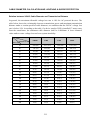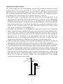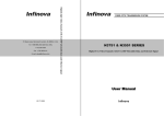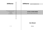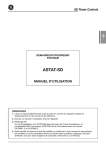
1
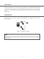
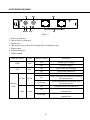
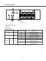
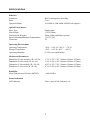
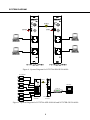
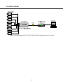
FIBER OPTIC TRANSMISSION SYSTEM 51 Stouts Lane, Monmouth Junction, NJ 08852, U.S.A. Tel: 1-888-685-2002(toll-free, USA) 1 SERIES 1-732-355-9100 Fax:1-732-355-9101 10/100/1000Mbps Ethernet Transceiver E-mail: [email protected] User Manual Infinova V2.3 1012 TABLE OF CONTENTS SERVICE NOTICE ................................................................................................................ 1 PRODUCT DESCRIPTION................................................................................................... 2 MAIN FEATURES................................................................................................................. 3 INSTALLATION.................................................................................................................... 4 POWER SUPPLY................................................................................................................... 4 N3787XA/XB-GE PANEL ..................................................................................................... 5 N3787XA-8FE PANEL .......................................................................................................... 6 SPECIFICATIONS ................................................................................................................. 7 SYSTEM DIAGRAM ............................................................................................................ 8 CABLE DIAMETER CALCULATION AND LIGHTNING & SURGE PROTECTION ... 10 SERVICE NOTICE The installation of this product should be made by qualified personnel. Do not attempt to service this product yourself. Refer all servicing to qualified personnel. If you require information during installation of this product or if service seems necessary, contact the local suppliers or Infinova at 1-732-355-9100 in 51 Stouts Lane, Monmouth Junction, NJ 08852 U.S.A. You must obtain a Return Authorization Number and shipping instructions before returning any product for service. Our obligation under this warranty is limited only to the repair or replacement of any of our products, provided that products are used within the specified ratings and applications, and that products are applied in accordance with good engineering practices, and that products are proved by our examination to be defective. This warranty does not extend to any Infinova products which have been subject to acts of accident, misuse, abuse, neglect, improper application or installation, improper operation or maintenance, connection to an improper voltage supply or to materials which have been altered or repaired outside an authorized Infinova factory repair center. Information provided by Infinova is accurate and reliable. However, no responsibility is assumed by Infinova for its use; nor for any infringements of other rights of third parties which may result from its use. No license is granted by implications or otherwise under any patent or patent rights of Infinova. WARNING TO REDUCE THE RISK OF FIRE OR SHOCK HAZARD, DO NOT EXPOSE THIS PRODUCT TO RAIN OR MOISTURE. DO NOT LOOK INTO OPTICAL PORTS WITH POWER ON. 1 PRODUCT DESCRIPTION Description N3787 series is Peer-to-Peer fiber optic transmission system released by Infinova as per the current market demands. By Ethernet transmission medium, it achieves switchover between twisted paired electrical signals and remote optical signals. With the rapid development of informatization construction, there is a growing demand for data, audio, image and other multi-media communication. Ethernet broadband connection is thus becoming more and more important. However, the traditional Category 5 cables can only achieve 100m transmission for the electrical Ethernet signal, which no longer meets the actual need in transmission distance and coverage scope. While fiber communication, with its large capacity, high security, light weight, small size, no relay and long transmission distance, is widely used in WAN and other large-scale network. It's applied for remote 1000M Ethernet data switch with large-capacity Peer-to-Peer transmission N3787 series single mode transmission system provides the ability to transmit 1000M Ethernet data over one fiber in full duplex and point-to-point mode. The Ethernet signal on two ends are 10/100/1000M self-adaptive. There are two or eight RJ45 Ethernet ports on the transmitter and receiver, easy to connect with different Ethernet devices. 2 MAIN FEATURES Storage and forward mode to match devices at different speeds Non-blocking wire-speed reception and transmission, transmission without head-of-line blocking Support feedback and diagnosis functions Detection and correction of port polarity at the physical layer Support IEEE802.1Q protocol Support 1000M optical port The Ethernet optical ports support full/half duplex (self-adaptive) Support IEEE 802.3x full-duplex flow control and back-pressure half-duplex flow control Support MAC address self-learning and update Support 802.1P protocol and QoS mechanism Compact structure for easy installation Hot swapping design With status indication for power, Ethernet and optical link 3 INSTALLATION To install the apparatus, it is necessary to allow enough space to accommodate the bend radius of the optical cable connected to it. The transmitter/receiver requires as short as practical Category 5 or 6 UTP cables to transmit Ethernet data. The RJ45 connector is applied for the Ethernet port. POWER SUPPLY The N3787 series is powered by a plug-in 24VAC@830mA power supply with 2-pin terminal block connector. Figure 1. External power supply Note: When the series is powered together with other devices (cameras and etc.) by a single 24VAC power source, please make sure that the related device has a full-wave (bridge) rectifier circuit. 4 OP PWR N3787XA/XB-GE PANEL Figure 2 1. Power on indicator 2. Optical link loss indicator 3. Optical port 4. Optical port (reserved for Wavelength Division Multiplexing) 5. Ethernet port 6. Ethernet indicator 7. GND terminal Indicator Name Color PWR Red OP Red Indicator Status Indication On Normal power supply Off No power supply On Optical link loss alarming Off Optical link connected Off Ethernet Port 10M/100M Ethernet disconnected 10M/100M Ethernet connected, without On 10/100 Green data transmission 10M/100M Ethernet connected, with Flickering data transmission Off 1000M Ethernet disconnected 1000M Ethernet connected, without data On 1000 Green transmission 1000M Ethernet connected, with data Flickering transmission Table 1. Indicator Instruction for N3787XA/XB-GE 5 N3787XA-8FE PANEL Figure 3 1. Power on indicator 2. Optical link loss indicator 3. Optical port 4. Ethernet port 5. Ethernet indicator Indicator Name Color PWR Red OP Red Indicator Status Indication On Normal power supply Off No power supply On Optical link loss alarming Off Optical link connected Off Ethernet Port 10/100 10M/100M Ethernet disconnected 10M/100M Ethernet connected, without On Green data transmission 10M/100M Ethernet connected, with Flickering data transmission Table 2. Indicator Instruction for N3787XA-8FE 6 SPECIFICATIONS Ethernet Connector: Ports: Operation Mode: RJ45 with magnetic shielding 2 or 8 10/100M or 10M/100M/1000M, self-adaptive Optical Performance Fiber Type: Wavelength: Transmission Distance: Speed of Forward/Reverse Transmission: Connector: Single-mode 1310/1550nm 20km, 40km and 80km optional 1.25G/1.25G FC Operating Environment Operating Temperature: Storage Temperature: Operating Humidity: -40°F ~ +165.2°F (-40°C ~ +74°C) -40°F ~ +185°F (-40°C ~ +85°C) 0~95% (non-condensing) Mechanical Parameters Dimension (2 slots module) (W ×H ×D): Dimension (2 slots card) (W ×H ×D): Dimension (1 slot module) (W ×H ×D): Dimension (1 slot card) (W ×H ×D): 1.73"×6.22"×7.56" (44mm×158mm×197mm) 1.58"×5.08"×6.58" (40mm×129mm×167mm) 0.95"×6.22"×7.56" (24mm×158mm×197mm) 0.79"×5.08"×6.58" (20mm×129mm×167mm) Reliability Mean Time between Failures (MTBF): >100,000 Hrs Status Indication LED Indicator: Power, optical link, Ethernet, etc. 7 SYSTEM DIAGRAM Figure 4. System Diagram for N3787XA/XB-GE-20/40/80 IP Camera Fiber PWR OP Monitor Switch N3787XA-8FE20/40/80 N3787XB-GE20/40/80 Figure 5. System Diagram for N3787XA-8FE-20/40/80 and N3787XB-GE-20/40/80 8 SYSTEM DIAGRAM Figure 6. System Diagram for N3787XA-8FE-20/40/80 and third-party FC switch 9 CABLE DIAMETER CALCULATION AND LIGHTNING & SURGE PROTECTION Relation between 24VAC Cable Diameter and Transmission Distance In general, the maximum allowable voltage loss rate is 10% for AC-powered devices. The table below shows the relationship between transmission power and maximum transmission distance under a certain specified cable diameter, on condition that the 24VAC voltage loss rate is below 10%. According to the table, if a device rated at 50W is installed 17-meter away from the transformer, the minimum cable diameter shall be 0.8000mm. A lower diameter value tends to cause voltage loss and even system instability. Diameter (mm) 0.8000 1.000 1.250 2.000 10 283 (86) 451 (137) 716 (218) 1811 (551) 20 141 (42) 225 (68) 358 (109) 905 (275) 30 94 (28) 150 (45) 238 (72) 603 (183) 40 70 (21) 112 (34) 179 (54) 452 (137) 50 56 (17) 90 (27) 143 (43) 362 (110) Distance (ft / m) Power (W) 60 47 (14) 75 (22) 119 (36) 301 (91) 70 40 (12) 64 (19) 102 (31) 258 (78) 80 35 (10) 56 (17) 89 (27) 226 (68) 90 31 (9) 50 (15) 79 (24) 201 (61) 100 28 (8) 45 (13) 71 (21) 181 (55) 110 25 (7) 41 (12) 65 (19) 164 (49) 120 23 (7) 37 (11) 59 (17) 150 (45) 130 21 (6) 34 (10) 55 (16) 139 (42) 140 20 (6) 32 (9) 51 (15) 129 (39) 150 18 (5) 30 (9) 47 (14) 120 (36) 160 17 (5) 28 (8) 44 (13) 113 (34) 170 16 (4) 26 (7) 42 (12) 106 (32) 180 15 (4) 25 (7) 39 (11) 100 (30) 190 14 (4) 23 (7) 37 (11) 95 (28) 200 14 (4) 22 (6) 35 (10) 90 (27) 10 Lightning & Surge Protection The product adopts multi-level anti-lightning and anti-surge technology integrated with gas discharge tube, power resistor and TVS tube. The powerful lightning and surge protection barrier effectively avoids product damage caused by various pulse signals with power below 4kV, including instantaneous lightning, surge and static. However, for complicated outdoor environment, refer to instruction below for lightning and surge protection: The product features with dedicated earth wire, which must be firmly grounded. As for surveillance sites beyond the effective protection scope, it’s necessary to erect independent lightening rods to protect the security devices. It’s recommended to separate the lightning rod from the mounting pole, placing the rod on an independent pole, as shown in the figure below. If the product has to be installed on the same pole or pedestal for lightning rod, there should be strict insulation between the video cable BNC terminal, power cable, control cable and the standing pole of the lightning rod. For suburb and rural areas, it’s recommended to adopt direct burial for the transmission cables. Overhead wiring is prohibited, because it’s more likely to encounter lightning strike. Use shielded cables or thread the cables through metal tubes for burial, thus to ensure the electric connection to the metal tube. In case it’s difficult to thread the cable through the tube all the way, it’s acceptable to use tube-threaded cables only at both ends of the transmission line, yet the length in burial should be no less than 15 meters. The cable sheath and the tube should be connected to the lightning -proof grounding device. Additional high-power lightning-proof equipment and lightning rods should be installed for strong thunderstorm or high induced voltage areas (such as high-voltage substation). The lightning protection and grounding for outdoor devices and wires should be designed in line with the actual protection requirement, national standards and industrial standards. The system should perform equipotential grounding by streaming, shielding, clamping and earthing. The grounding device must meet anti-interference and electric safety requirements. There should be no short-circuiting or hybrid junction between the device and the strong grid. Make sure there’s a reliable grounding system, with grounding resistance below 4Ω (below 10Ω for high soil resistivity regions). The cross-sectional area of the earthing conductor should be no less than 25mm². LPZOA 30° 30° Lightning rod LPZOB Front device for surveillance system Mounting pole for front device Separated layout for the lightning rod and the standing pole 11 FIBER OPTIC TRANSMISSION SYSYEM 51 Stouts Lane, Monmouth Junction, NJ 08852, U.S.A. Tel: 1-888-685-2002(toll-free, USA) 3732 & 3532 SERIES 1-732-355-9100 Fax:1-732-355-9101 E-mail: [email protected] Digital one video with 4-ch audio-and-data User Manual Infinova V 130