1
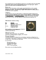
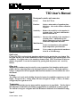
T3D User’
s Manual
Front panel controls and connectors
Power:
Turns the T3D on.
Function:
Selects various modes of operation when
held down. Also used to initiate calibration
sequence.
Sensitivity -:
Reduces the sensitivity to the transducer’
s
resonant points. Also used with Function
button to turn unit off.
Sensitivity +: Increases the sensitivity to the transducer’
s
resonant points. Additionally used to
display temperature in degrees Fahrenheit
when in the temperature test mode.
Multi-function:
Used to test transducers with combined
depth-temperature-speed functions.
Standard:
Use to connect to piezoelectric transducers
in the 50 to 500 kHz range.
Quick start
Connect the T3D to a piezoelectric transducer and turn it on by pressing the power button. The
bar graph will show one or more illuminated sections corresponding to the resonant points of the
transducer. If no lights come on, the transducer element is bad. The T3D will turn off after two
minutes of operation. It can also be turned off by pressing both the function and -sensitivity
buttons.
Other tests
Multifunction transducers may be tested for correct operation of the thermistor and the speed
paddle wheel by connecting them to the 8-pin multi-function connector. The 8-pin connector
wiring is configured for the most popular multi-function transducers and is detailed at the end of
this manual.
Leakage
The leakage test is activated by holding the function button down until the segment next to leak
flashes. An open circuit (> 10 meg ohms) will cause all segments to light. A short (<10 ohms)
will light only the segment next to 0.
Temperature
Again press and hold the function button until the segment next to temp blinks. The first digit of
the temperature is indicated by the flashing segment and the second digit by a steady segment.
The readout is in degrees centigrade unless the E
F button is held down for a Fahrenheit reading.
Speed
T3D User Manual
030705
Press and hold the function switch until the segment next to speed lights. Rotate the speed paddle
wheel and the 0 and 1 segments will light indicating the state of the output signal. Spin the
paddle wheel rapidly and the bar graph lights progressively.
Battery test
When the T3D is first turned on, all bar graph segments flash briefly to test the segments,
followed by one segment. The position of this segment displays the battery voltage. If it
illuminates at 6 or lower, change the battery. Replace with an alkaline 9 volt battery similar to
EVER READY #522 or equivalent.
Calibration
To insure the best accuracy the T3D should be re-calibrated if the ambient temperature has
changed by 30 degrees Fahrenheit or more relative to the last calibration. To calibrate the unit
the power must be off and no transducer connected. With the unit in the power off condition,
press and hold the function button then press the power button. Do not release the function
button for three seconds. Successful calibration is indicated when all segments go out.
Multi-function connector wiring:
pin
function
1
2
3
4-5, 7-8
6
Speed sensor signal.
Speed sensor +5 VDC power.
Transducer element.
Ground connections.
Temperature sensor.
Pin 1 is at the five o’
clock position as viewed from the
front panel and the pins are counted in a
counterclockwise direction.
Optional Accessories
Test Cable (RCA to Clip Leads) P/N 004-TESTC
8 pin Jack (for making Transducer Adapters) P/N 520-001
Warranty Information
Unit will be repaired free of charge for one year from date of purchase providing there is no
water damage or other evidence of improper use or handling. Purchaser must ship unit prepaid
to address below; EDI will pay the return freight.
For repair ship to:
Electronic Devices, Inc.
3140 Bunch Walnuts Road
Chesapeake, VA. 23322
ATTN: Service Department
Please enclose a note describing the problem.
T3D User Manual
030705