1
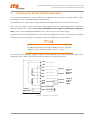
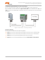
Pancode VoIP Pantel VoIP Access Control Door Phones Installation and Programming Manual Version 2 Pre-Release 2 October 2007 Pancode VoIP/Pantel VoIP Access Control Door Phones Installation and Programming Manual NOTICE This publication refers to the PANCODE IP and Pantel IP Door Access Control devices, Release 2. Additional copies of this manual may be obtained from ITS Ltd. Reproduction of this manual or parts thereof without written permission from ITS is strictly prohibited. ITS Ltd. reserves the right to modify the hardware and software described herein without prior notice. However, changes made to the hardware or software described do not necessarily render this publication invalid. WARRANTY In the event that the product proves to be defective in workmanship or materials within a period of one year from date of shipment, ITS Ltd. shall repair or replace the same at its discretion. Transportation will be the responsibility of the dealer/distributor. Under no circumstances shall ITS Ltd. be liable for consequential or special damages, loss of revenue or user/dealer expenses arising out of or in connection with the use or performance of the product, whether base on contract, tort or any other legal agreement. The following shall void the above warranty: malfunctions resulting from fire, accident, neglect, abuse or acts of God; use of improper electrical power; or repair of, tampering with or alteration of the product by anyone other than ITS authorized. Pancode VoIP/Pantel VoIP Access Control Door Phones Installation and Programming Manual Table of Contents 1. Introduction ...............................................................................................................................................2 1.1 2. Pancode VoIP/Pantel VoIP Kit Contents............................................................................................3 Physical Description....................................................................................................................................4 2.1 Pancode VoIP Front Panel ................................................................................................................4 2.2 Pantel VoIP Front Panel....................................................................................................................5 3. Installation .................................................................................................................................................6 4. Pancode VoIP/Pantel VoIP Schematic Setup ................................................................................................7 5. Installing the Pantel VoIP/Pancode VoIP ......................................................................................................8 6. Adjacent Access Control Device ...............................................................................................................11 7. Programming ...........................................................................................................................................13 8. 7.1 Searching for a Device in LAN........................................................................................................13 7.2 Application Interface .....................................................................................................................14 7.3 System Parameters ........................................................................................................................15 7.4 VoIP Dialing settings......................................................................................................................18 Technical Specification .............................................................................................................................21 1 Pancode VoIP/Pantel VoIP Access Control Door Phones Installation and Programming Manual 1. Introduction This guide provides installation and programming instructions for the following products: Pancode VoIP outdoor piezo keypad unit Pantel VoIP outdoor piezo keypad unit The Pancode VoIP and Pantel VoIP are smart wall-mounted access control door phones connected to a local Voice Over IP (VoIP) network of a VoIP PBX, allowing door entry control. They are available for outdoor installation in an aluminum unit with a piezo keypad. As an option, these units can be equipped with an internal black & white or color high-quality pinhole camera. The Pancode VoIP and Pantel VoIP have the following features: Feature Pancode VoIP Pantel VoIP Integration with local LAN and VoIP networks U U Authorized registration with existing VoIP switching system (Proxy) U U Two different operation modes: Standard – for direct dialing to any destination number Speed-dial – for one-touch dialing to internal or external subscribers U X Automatic busy & disconnect detection U U Door opening from any extension U U Door opening from Bypass Switch button U U Programmable day and night destinations U U High quality speakerphone with separate volume control U U Entry access code (supports up to ten codes) U X Works in conjunction with card readers and security devices U U Programming via Ethernet interface using a web-based GUI application U U Acoustic echo canceller U U Automatic gain control (AGC) U U SRTP (encryption and authentication) U U Support for video over VoIP (optional) U U Smart looking durable design U U 2 Pancode VoIP/Pantel VoIP Access Control Door Phones Installation and Programming Manual 1.1 Pancode VoIP/Pantel VoIP Kit Contents The contents of the Pancode VoIP/Pantel VoIP are as follows: Pancode VoIP or Pantel VoIP unit External 12V AC power supply Ethernet cable Installation CD 3 Pancode VoIP/Pantel VoIP Access Control Door Phones Installation and Programming Manual 2. Physical Description The Pancode VoIP and Pantel VoIP are attached to the wall using a bracket and screws. These units are hardwired and powered by an external 12V AC transformer, included in the package. The Pancode VoIP and Pantel VoIP dimensions are: Height: – 19.4 cm Width: – 10.2 2.1 Pancode VoIP Front Panel The front panel of the Pancode VoIP unit contains a built-in speaker, a microphone and a touch-keypad (Figure 1). Speaker Keypad Microphone Figure 1. Pancode VoIP Front Panel 4 Pancode VoIP/Pantel VoIP Access Control Door Phones Installation and Programming Manual 2.2 Pantel VoIP Front Panel The front panel of the Pantel VoIP unit contains a built-in speaker, a microphone and a touch-keypad (Figure 2). Speaker Call Button Microphone Figure 2. Pantel VoIP Front Panel 5 Pancode VoIP/Pantel VoIP Access Control Door Phones Installation and Programming Manual 3. Installation The Pantel VoIP/Pancode VoIP is mounted on the provided installation bracket. This mounting bracket should be installed as shown in Figure 3. Figure 3. Installation Bracket To install the wall bracket: a. Measure and mark the location on the wall where the holes will be drilled for the mounting bracket. b. Drill the holes and insert the wall anchors into the holes. c. Attach the mounting bracket using the provided wall screws. 6 Pancode VoIP/Pantel VoIP Access Control Door Phones Installation and Programming Manual 4. Pancode VoIP/Pantel VoIP Schematic Setup The Pancode VoIP/Pantel VoIP unit is connected to the VoIP PBX as a SIP extension or via any IP router (Network HUB, Switch etc). The unit powers the door lock, provided it is powered by an external supply and not PoE. Figure 4 details the unit schematic setup. PBX VoIP Network/ LAN Pancode VoIP/ Pantel VoIP Extension Door Lock TV Monitor Figure 4. Schematic Setup 7 Pancode VoIP/Pantel VoIP Access Control Door Phones Installation and Programming Manual 5. Installing the Pantel VoIP/Pancode VoIP The Pantel VoIP/Pancode VoIP can be installed as an individual access control or used with adjacent accesscontrol devices, such as card reading devices (see Section 6). The provided 12V AC external power supply should not be located further than 10m (30ft) from the unit. These units also support Power Over Ethernet (PoE), meaning that they could operate when connected to Ethernet without mains. However, the current provided by the PoE supply is insufficient for opening a door. If your system is equipped with door lock relay, make sure to use the external supply. Figure 5 shows the terminal locations on the wire connector provided with the unit. This connector is attached at the base of the internal component. All wiring to the unit is attached to the wire connector. There may be LINE pins in the connector, but they are not active with this product and cannot be used. When holding the unit as displayed in Figure 6, the first pin from the right is the first ~12V pin. The Pantel VoIP/Pancode VoIP supports a bypass switch installation. This allows opening the door with a hardwired switch. A bypass switch should be connected to the SW and /SW terminals. ~12V ~12V N.C. option 1 CMN N.O. option 2 Connect to an External Device DLR ~DLR ~DLR /DLR option 3 option 4 Connect to Door Lock Relay Bypass Switch (SW) Contact Detection Bypass Switch (/SW) Figure 5. Connectors Scheme 8 Pancode VoIP/Pantel VoIP Access Control Door Phones Installation and Programming Manual For the installation of the powered-unlocked-state, use DLR and ~DLR. For the installation of the powered-locked-state, use /DLR and ~DLR (this is recommended for safety purposes). The wiring connector is a screw connector type. In order to attach a wire, you must insert the stripped end of the wire into the proper terminal and tighten the terminal screw. This will crimp the wire connection. To Install the Pantel/Pancode VoIP: a. Remove the cover from the Pantel VoIP/Pancode VoIP unit and disconnect the wire connector, found at the base of the internal component. b. Connect the two 12V lead wires from the 12V AC power adapter, one to each of the “~12V” terminals (Figure 5). c. Connect the Ethernet cable to the RJ-45 LAN socket (Figure 6 and Figure 7) by means to program the unit using the Web-based GUI (see Section 7). d. Connect the door-lock relay wires to the “DLR” and “~DLR” terminals - or If the door-lock relay is a powered-locked-state type lock, connect the door-lock relay wires to the “/DLR” and “~DLR” terminals. e. If a push button switch is used, connect the push button wires to the “SW” and the “/SW” terminals. f. Plug the wire connector to the base of the unit’s inner component. g. Switch on the power to the 12V adapter. 1. After power-up or reset, the Pancode/Pantel device starts an initialization process, which can take up to 20 seconds. The initialization completion is indicated by short busy signal. 2. Device can be detected in the LAN by using the MAC address shown on the label. 3. When SIP parameters are updated, an automatic power reset is required. The programming is not done in real time. Make sure to apply the settings to the unit by selecting CommunicationÆSend Parameters on the main menu. 9 Pancode VoIP/Pantel VoIP Access Control Door Phones Installation and Programming Manual Ethernet RJ-45 ~12V Connector Wire Connectors Figure 6. Unit Connectors M 1 8 F Figure 7. RJ-45 Connector 10 Pancode VoIP/Pantel VoIP Access Control Door Phones Installation and Programming Manual 6. Adjacent Access Control Device This section describes adding an access-control device to an existing Pantel VoIP/Pancode VoIP, and adding a Pantel VoIP/Pancode VoIP to an existing access-control device. The key difference between these two installations is which access-control device controls the door lock relay. To add an access control device to a Pantel VoIP/Pancode VoIP: When activated, the access-control triggers the Pantel/Pancode “SW” terminal, which activates the door-lock relay and opens the door. For this type of installation, the access-control device “N.O.” output wires are connected to the Pantel VoIP/Pancode VoIP Switch terminals (see Figure 8). Lock Relay Switch N.O. Output Figure 8. Controlling Lock Relay 11 Pancode VoIP/Pantel VoIP Access Control Door Phones Installation and Programming Manual To add a Pantel VoIP/Pancode VoIP to an access control device: The access control device opens the door when the Pantel/Pancode triggers the access-control device. For this installation, the access-control device “Bypass Switch” (SW) wires are connected to the “N.O.” and “CMN” terminals of the Pantel/Pancode. The door-lock relay wires are connected to the access-control device (see Figure 9). Lock Relay N.O. & CMN Figure 9. Access Control – Controlling Lock Relay Connection schematics: The Pantel VoIP and Pancode VoIP offer multiple wiring options: Option 1: For use with an external device, which requires the unit to be set up as “Normally Closed”. Option 2: For use with an external device, which requires the unit to be set up as “Normally Open”. Option 3: For use with the powered-unlocked-state lock relay (most common). Option 4: For use with the powered-locked-state lock relay (recommended for safety purposes). 12 Pancode VoIP/Pantel VoIP Access Control Door Phones Installation and Programming Manual 7. Programming The Pancode VoIP/Pantel VoIP units are programmed through web-based GUI interface. This process can be implemented after the unit has been installed on the wall, since it requires the connection of an Ethernet cable to the local network. The programming application is launched from the web browser (preferably MS Internet Explorer version 5.5 or higher). It is possible to run the application by typing the following address in the address bar: http://XXX.XXX.XXX.XXX/pancode (Figure 10). Figure 10. ITS Pancode IP Web Page 7.1 Searching for a Device in LAN When the IP address is unknown, it is possible to find the unit in the LAN using the QUERY utility from the installation CD. Unit location through a query is possible only when the unit MAC address is known. It appears on the label attached to the rear panel of the device. To find the unit in the network: a. Insert the installation CD and copy the query.exe file from Software directory to the local hard drive. b. Start MS Windows DOS prompt application. c. Access the directory, in which the query.exe application exists. d. Enter the following command: query XX:XX:XX:XX:XX + <Enter>, where XX:XX:XX:XX:XX is the MAC address. A search for the device takes place, at the end of which the unit IP address appears (Figure 11). Figure 11. Searching for Device Using Query 13 Pancode VoIP/Pantel VoIP Access Control Door Phones Installation and Programming Manual 7.2 Application Interface When running the application, the main screen opens, comprising the navigation menu, parameters fields and functional buttons (Figure 12). Figure 12. Application Interface The navigation menu contains the following items: System Authorization parameters Local network parameters Proxy server parameters Codec Type Volume settings Time mode DHCP support Dialing mode Door opening time Auto Answer mode Video Camera operational mode (optional*) * Video camera operational mode depends on the Door Unit’s hardware configuration. 14 Pancode VoIP/Pantel VoIP Access Control Door Phones Installation and Programming Manual VoIP Dialing Settings Speed dialing mode Door Access Codes Speed dialing mode destination numbers Regular (Normal) Direct dialing mode First digits of Extensions Regular (Normal) dialing mode Door Access Codes Call Button definitions Door opening from extension code No answer timeout The Main Parameters screen contains the following operational buttons: Submit Upload modified settings to the Door Unit Reset to default Reset Door Unit to the factory default settings Reboot Restarts the Door Unit Upload Config File Upload previously saved Door Units configuration file. ( Note: Saved file renamed to Config.CFG) Save Config File Save existing Door Panel configuration as file on local PC drive (the existing configuration file will be saved with extension Config.SAV. For uploading this file need to rename saved file to extension Config.CFG) Upload Firmware Activate the updating of the Door Unit’s internal firmware. This operation requires original firmware file provided by manufacturer or local dealer. Upload Kernel 7.3 System Parameters The following table details the system parameters. You may require assistance from your LAN administrator. Parameter Name and Parameters area: Parameter Description Account Name (username) Contains the unit identification as an SIP proxy server account or VoIP peer-to-peer network. Legal entry: 5 to 20 characters 0-9, A-Z, a-z. Account Password (password) Contains the unit authorization on the SIP proxy server. Legal entry: 5 to 20 characters 0-9, A-Z, a-z. IP Address – Local Address Identifies the Pantel VoIP/Pancode VoIP device on the TCP/IP network. Legal entry: digits 0-9 only. Example: 192.168.21.10. Subnet Mask A mask that determines to which subnet an IP address belongs. Legal entry: digits 0-9 only. Example: 255.255.255.0. Default Gateway An identifier for the default gateway on a TCP/IP network for cases, when the Proxy server presents out of local LAN network. Legal entry: 0-9 digits only. Example: 192.14.21.210. 15 Pancode VoIP/Pantel VoIP Access Control Door Phones Installation and Programming Manual Parameter Description User Domain In most cases it is the same as the Registar Address (Proxy server IP address). In special cases it is required to enter Company Domain IP address. Registar Address (Proxy IP An identifier for the SIP Proxy server on a TCP/IP network. Legal entry: 0-9 field) digits only. Example: 192.14.21.210. Registar port (Proxy Port field) Designed to contain the number of the TCP/IP port used by the unit for communication with SIP Proxy server (IP-PBX). Default port: 5060. Legal entry: Up to 8 digits (0..9). Auto Registration Registration expire Displays the time interval for the unit to register on the Proxy server and to (Registration Interval) indicate Live status. Legal entry: 0-9999. The setting in this field takes effect only when Enable Auto Registration checkbox is selected. Codec Type A Low/MU Low options – enable to select between VoIP codecs supported by the PBX. Unit Volume level Microphone Volume – enables to set the microphone volume level as a two-digit parameter. Legal entry: 00 – 63 (00 sets Mute mode). Far End (Speaker) Volume Speaker Volume – enables to set the speaker volume level as a two-digit Level parameter. Legal entry: 00 – 63 (00 sets Silent mode). VAD (Voice Activity When checkbox is selected, activates a field under it. This field contains a Detection) Threshold virtual value (0-256) that represents a threshold for human voice detection. When voice is detected, the unit will establish a connection with the extension according to the programming in Day and Night numbers (recommended value 20-25). Auto Start This parameter is required for manufacturing purposes only. DSP Firmware version (Voice Switching between Full and Half duplex voice transmission modes. Legal Operational Mode) entry: 1 – half-duplex mode; 2 – full duplex mode. Enable DHCP Enables DHCP service support. IP Door panel will get IP settings automatically in case that DHCP server is present in the LAN. Product Type List of available IP Door Panel configuration and functionality. These settings define the device functionality as a panel or Pancode. Dial Mode Standard dialing – sets the unit to standard dialing operation mode. In this mode, it is possible to make a direct call to an extension or enter a door-opening access code. Speed-dialing – sets the Pancode VoIP to speed-dialing operation mode. In this mode, it is possible to make a call using a two-digit speed dial code (11 to 35) to internal or external subscribers. 16 Pancode VoIP/Pantel VoIP Access Control Door Phones Installation and Programming Manual Parameter Description Time mode Day mode and Night mode – enables to select the operational mode of the unit. Number of Door Access Code error retries, when IP Door Panel will Number of errors implement calling to Error Number Panel Session Time Out Call max. duration – displays the time interval for conversation with the (Maximum Conversation target phone’s subscriber. You may insert the time parameter in two-digit time) format in seconds. Legal entry: 10-99 seconds. Unlimited time interval with the 00 settings. Door open time Open door interval – enables to set the time interval during which the door lock remains open. VCR Mode * Parameter defines the digital camera functionality. * Depends on the firmware and hardware configuration. Contact local dealer or manufacturer for further details. Low mode (GCI) General Circuit Interface is the second of two standard synchronous 2B+D ISDN timing interface modes with which this device is compatible. In the GCI mode, the device can communicate in either of the two 64 kbps B– channels. This parameter may be changed by a qualified and authorized person only! Idl Mode The Interchip Digital Link interface is one of two standard timing interface modes with which this device is compatible. In the IDL mode, the device can communicate in either of the two 64 kbps channels. This parameter may be changed by a qualified and authorized person only! Presentation Name Displays the name that will appear on the digital station display when a call is received from the unit, depending on the VoIP PBX support for this feature. Auto Answer TFTP Server IP address An identifier for the TFTP server on a TCP/IP network, where configuration files will be stored. The TFTP server can be activated by using the Third Part Company tftp software. For example: Tftpd32 application, which can be found on the following URL: http://www.snapfiles.com/download/dlTftpd32.html ) Config. File name Previously saved configuration file name, which has to be written here and IP Door Panel will upload it using tftp server settings. Firmware file name Internal IP Door Panel Firmware file name. Uploading procedure is the same as Configuration file. Kernel File name Internal IP Door Panel Kernel file name. Uploading procedure is the same as Configuration file. This parameter may be changed by a qualified and authorized person only! 17 Pancode VoIP/Pantel VoIP Access Control Door Phones Installation and Programming Manual Parameter Description IP Camera Type * Type of the digital video camera used in the IP Door panel. IP Camera Enabling DHCP * Enables the DHCP mode for the digital video camera. IP Camera IP Address * Identifies the Pantel VoIP/Pancode VoIP digital video camera on the TCP/IP network. Legal entry: digits 0-9 only. Example: 192.168.21.10. IP Camera Subnet mask* A mask that determines to which subnet an IP address belongs. Legal entry: digits 0-9 only. Example: 255.255.255.0. IP Camera Gateway * An identifier for the default gateway on a TCP/IP network. IP Camera stream Type * The video stream type supported by the digital video camera. * Feature activity depends on the IP Door Panel hardware and software configuration. Contact the local dealer or manufacturer for details. Software Version Displays the IP Door panel internal software number. Hardware Version Displays the IP Door panel internal hardware edition number. 7.4 VoIP Dialing settings The VoIP Dialing Parameters screen displays the dialing and door opening definitions. Pancode VoIP has two dialing modes: standard and sped-dial. Pantel VoIP has the standard mode only. The VoIP Dialing screen contains the following areas: Parameter Name and Parameters area: Parameter Description DTMF Transfer type Defines the mode of providing DTMF tone information in the SIP VoIP network. Possible choice: RFC 2833 or Transparent (In-Band DTMF). Speed Access Codes 1 to 10 Access Door Opening Codes (speed-dial mode) fields – contain dooropening codes in speed-dial mode. Each field can contain a code of up to 8 digits, which opens the door lock. Legal entries: 0-9 digits only. All codes in this mode must start with 0. 18 Pancode VoIP/Pantel VoIP Access Control Door Phones Installation and Programming Manual Parameter Description Regular Prefix Prefix for direct dialing field – contains the first digit of a target phone number, to which it is possible to call directly. You can enter up to eight prefixes using a coma separator. Example: Defined prefixes 1, 2, 5 enable to dial directly to numbers beginning with 1, 2 or 5. Digits defined as a direct call prefix may not be used as first digits for access door opening code. Speed Dialing Numbers The direct dialing feature requires a SIP proxy definition. In case of PeerTo-Peer mode, VoIP gateway IP address can be used as destination and set in the SIP proxy address. Speed dialing subscribers list – contain from to 2 to 20 lengths of (Destination numbers) 11 – 35 subscriber’s phone numbers. Legal entry: 0..9, *. It is possible to enter 25 codes indexed from 11 to 35. If an IP address is used as a destination, use following format: *XXX*XXX*XXX*XXX, where XXX are digits, the address is prefaced by an asterisk and an asterisk is used as a separator. The access door-opening code in speed-dial mode must start with 0. Call Button Dialing – Day Day number field – contains the number of the target phone, which will Mode destination be dialed when a visitor presses the Call button when the device is configured to operate in Day mode. You may insert up to 20 entries, so that a visitor could call different extensions directly. Legal entry: Digits 0-9, ABCD, *. Call Button Dialing night Night number field – contains the number of the target phone, which mode destination will be dialed if a visitor will press the Call button when the device is configured to operate in Night mode. You may insert up to 20 entries, so that a visitor could call different extensions directly. Legal entry: digits 0-9, ABCD, *, #. Call Button Dialing Error Error number field – contains the number of the target phone, which will mode destination be dialed if a visitor will dial an incorrect access entry code more than three consecutive times. You may insert up to 20 entries. Legal entry: digits 0-9, ABCD, *, #. Call Button Dial no Answer Contains the number of the target phone, which will be dialed if a (Forward No Answer) destination number dialed by visitor is not answer during specific time interval. You may insert up to 20 entries. Legal entries: digits 0-9, ABCD, *, #. See also “ No Answer Time Out” parameter Open Door Activation (Door – enables to set a code of up to four digits, which could be dialed from opening code from extension) any extension during conversation to open the door. 19 Pancode VoIP/Pantel VoIP Access Control Door Phones Installation and Programming Manual Parameter Description Access Codes 1 – 10 Access Door Opening Codes fields – contain door opening codes. Each field can contain a code of up to 8 digits, which opens the door lock. Legal entries: 0-9 digits only. An access door-opening code cannot begin with digits that are used as direct call prefix number. Peer IP Address Specify the target Peer device IP address when Peer mode is activated. Peer Mode Used mostly for functionality testing purposes. Specify the following type of operation: Visitor dials any free up to 3 digits number and IP Door panel try to establish SIP connection with the target Peer device, where dialed digits used as fourth quarter of the IP address. For example: No answer Time Out Peer IP Address is 192.168.21.XXX, where last XXX digits are insignificant. Visitor dialed 151. Door panel started to establish connection with the IP address 192.168.21.151 Time interval, when a call will be forwarded to the another destination specified in the Call Button Dial no Answer (Forward No Answer) parameter when destination dialed by visitor did not answer. Off Hook Time Out This parameter is relevant if the Auto Answer mode is disabled. Specify a maximum time interval in seconds, when the IP Door Panel can be in the No Answer mode during incoming call before rejecting the call. 20 Pancode VoIP/Pantel VoIP Access Control Door Phones Installation and Programming Manual 8. Technical Specification Power supply 12V AC; 1.5A or Power Over Ethernet IEEE 802.3af compliant Communication interface Ethernet for voice; and for programming DC Leakage <10 µA Imbalance ratio 300-3400Hz > 46dB Return loss 300-3400Hz > 18dB Relay switching current 2A max VoIP protocol supported SIP; RTP; RTCP Supported codecs G.711 PCM (µ/A-Law) at 64 kbps G.726 ADPCM at 16-40 kbps G.727 E-ADPCM at 16-40 kbps G.729 A/B CS-ACELP at 8kbps G.723.1 MP-MLQ at 6.3 kbps G.723 ACELP at 5.3 kbps GSM 6.10 Full Rate at 13.2 kbps GSM Enhanced Full Rate 12.2 kbps AMR at 4.75-2.2 kbps G.729E at 11.8 kbps Echo canceller G.168-2002 Compliant with programmable echo tail of up to 128 msec. Full duplex, acoustic EC Quality Enhancement Comfort Noise generation (CHG) Packet Loss Concealment (PLC) Adaptive Jitter Buffer(up to 300 msec) Echo canceller length Up to 64 msec IP media features Automatic Gain Control In-Band Signaling Detection and Generation DTMF TIA464B Dimensions 19.4 X1 0.2 cm Weight 0.9 kg Operating temperature -20ºC to +50ºC/4ºF to 122ºF 21