1
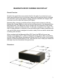
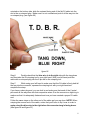
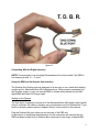
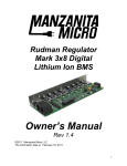
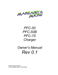
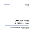
“RBD” Rudman Bus Display User’s Manual Rev 0.3 ©2011 Manzanita Micro LLC and Bruce Sherry Designs The information date is: 05/12/2011 1 CONTENTS GENERAL OVERVIEW……………………………………………………… Page 3 PRODUCT DIMENSIONS..…….…………………………………………... Page 3 KEY FEATURES LIST………………………………………………………..Page 4 SETUP…........………………………...............................…...……………..Page 5 -RBD Connections..................................................................................Page 5 - Regbus Ports....................................................................................... Page 5 THE REGBUS INTERFACE………………………………………………… Page 6 -Pinout Description…………………………………………………………. Page 6 INSTALLING THE UNIT…………………………………………………….. Page 6 WIRING THE RBD................................................……………………….. Page 7 -Reg Bus Wiring.....................................................................................Page 7 - Reg Bus Cable Construction……………………………………………. Pages 8-9 CONNECTING WITH THE DIGITAL INTERFACE………………………. Page 9 - Using the RBD and its Graphic User Interface...................………… Page 9 - Setting up the System............…………………………………………... Page 9 - Understanding the Battery Display Screen………………….......…… Pages 10-11 MANZANITA MICRO CONTACT INFO…………………………………… Page 12 2 MANZANITA MICRO RUDMAN BUS DISPLAY General Overview Wouldn't it be great if there was a device that fit in the palm of your hand (or in your dash) which would allow you to look at your battery pack at any given point in time and see information such as pack State of Charge and even individual cell voltages? Well now there is and it's called the Rudman Bus Display! Manzanita Micro teamed up with Bruce Sherry Designs and is pleased to offer the Rudman Bus Display (RBD) unit which will work with any device in the Manzanita Micro Mk3 digital series. The RBD gives users a compact full-color interactive touch-screen display which requires nothing more than 12 volts and a connection to the regbus. The days of being tethered to a computer to read and adjust specific battery parameters are over and this little device is designed to be able to easily fit into an electric vehicle dash or battery pack enclosure. When combined with the Manzanita Micro SOC Head, the RBD will show a clear depiction of the battery S.O.C. (State of Charge) like a fuel gauge. When connected to any Mk3 digital BMS (Battery Management System) the RBD can show a live bar graph depiction of each individual battery or cell. This allows the user to easily spot weak cells that might only show themselves during actual use. Dimensions 3 MANZANITA MICRO RUDMAN BUS DISPLAY KEY FEATURES The ability to monitor a very wide variety of battery packs from a single cell to extremely high voltage packs of up to 254 cells Auto-detect function makes setup a breeze as the unit will find all valid Mk3 products that are connected to it in a matter of seconds The ability to display continuously updating individual voltages from any battery or cell when reading from any Manzanita Micro Mk3 series BMS Able to display a clear battery pack State of Charge gauge when reading from a Manzanita Micro SOC Head Compact and durable enclosure is about H 1.25” x W 2.5” x L 4.5” not including the I/O connections. (H 32mm x W 64mm x L 114mm) Bar Graph columns change color to indicate high and low battery conditions Can be connected independently or in conjunction with other Manzanita Micro Mk3 Digital products using readily available six conductor RJ cable Allows easy viewing of battery information and parameter adjustment without the need for a laptop or full-size computer or even a dongle terminator box Simple touch-button graphic user interface for changing settings with or without typing commands The RBD makes it easy to adjust min and max voltage parameters for use with just about any battery pack and for fine tuning Dual RJ reg bus ports for easy connection between the charger and/or other Manzanita Micro BMS units and accessories Unit retains a memory of the last devices and display configurations making it able to be turned on and off or lose power without losing the last settings 4 Setup Everything is already loaded and built-in making the RBD truly plug and play. Simply plug Manzanita Micro regbus connection in, supply power to the unit with 12 volts and then follow the configuration instructions in this manual to start viewing battery data. RBD Connections figure 02 Regbus Ports - RJ Connections On the rear side of the unit next to the 12 volt power input connector are the In/Out ports for the reg bus communication. These are standard 6 pin RJ data connections. Either one or both of these ports allow the RBD to be connected into the regbus. Even if there are other units connected on the regbus the precise order does not matter as each unit should be individually programmed with its own specific bus address identification number. NOTE: The RBD cannot be used when another external interface device is using the Rudman Bus communication lines. The RBD does not require a dongle terminator (DT box) in order to communicate with the other MK3 digital devices on the bus. If another device such as a PC is trying to communicate over the 5 Rudman Bus using a properly attached DT box and the RBD is also plugged into the bus, this can create problems as they both try and communicate at the same time. The current design only allows for one external communication device. The REGBUS Interface: The REGBUS communicates important information back to the charger such as whether any regs are regulating or not and whether any heat sink channels are too hot. The charger uses this information to determine when to turn down the charge current and when to turn off the charger. In addition, the REGBUS also transmits the digital information. This digital information can be directly exchanged with the RBD unit by simply plugging in the Rudman Bus cable to the back of the unit and making sure the unit is powered up and turned on. The REGBUS interface contains five wires connected as follows: 1. Power supply (+5 volt DC) 2. Battery overvoltage condition (reg ON or reg hot) – +5V on this line when active 3. Battery Undervoltage condition – 0V on this line means undervoltage active 4. Power supply return Ground (GND) CAUTION: The GND return is NOT isolated on older Manzanita Charger models. 5. Rudman bus negative 6. Rudman bus positive Note: The pin count reads from left to right when looking straight on into the RJ receptacle. Refer to figure 02. All measurements are made relative to the GND wire. It is important to verify all six of the wires are continuous throughout the system. CAUTION: On older PFC charger models, the GND on the REGBUS is not isolated from battery negative. The primary functions of the REGBUS are: 1. Supply power to the charger side of BMS units 2. Support analog data exchange from BMS to charger and real-time analog control 3. Support digital data transfer and control of the SOC Head and/or BMS via the Rudman Bus (modified EVILbus) Installing the Unit: The RBD is built into a sturdy metal case. It is the responsibility of the user to fashion a suitable mount for the unit. Brackets, straps or even strong velcro may be suitable. 6 Wiring the RBD: 12 Volt Power: The RBD unit requires 12 volts. The actual input voltage range it will accept is between 10 and 15 Volts. There should be a solid 12 or 15 volts for optimum communcation over the Rudman Bus. Reg bus Wiring: All Manzanita Micro Mk3 digital hardware products are connected with a 6 pin RJ data cable allowing them to communicate both digitally and with some analog signals over the Rudman Bus lines. These communication lines can connect the RBD, charger and/or all of the BMS units in a daisy chain fashion. It does not matter where in the chain it is connected as long as it is programmed with a bus address different from any other unit(s) on the bus. Regbus Cable Construction; The 6-wire RJ cable which is used to connect the regulators is a common data transfer cable and is available at most electronics stores. The 6-pin connector plugs are usually clear and it is easy to crimp them using an appropriate crimping tool with a 6-pin die. These are also readily available. NOTICE! RJ cable is quite rugged but take care not to cut or sharply bend (and fatigue) the cable in order to avoid errors from broken internal wires. Additionally, follow the proper cable construction techniques listed below and make sure that all the wires are installed in the correct orientation. (See figure 06) Proper Regbus cable construction is not difficult but it requires keen attention to detail on the part of the person installing the plug ends onto the RJ cable. The following steps tell how to correctly make a regbus cable suitable for use with any 6-Pin Manzanita Micro product. Step 1: Cut the RJ cable to the desired length. (It is advisable to err on the long side because each of the cable’s ends will be pushed to the back of their respective RJ receptacles. Step 2: Strip about a quarter inch of the thick “flat” outer jacket off of each end of the cable in order to expose the 6 colored wires inside. Most RJ crimping tools will have a special wire stripping section with a guide which will allow you to quickly strip the correct length of cable jacket off. Step 3: Hold the flat RJ cable in front of you in your left hand with one end pointing towards you and one away from you. Step 4: Looking down at the cable in your hand make sure that the end facing away from your body has the blue wire to the right side. Step 5: Now take an un-crimped plug-end in your right hand and with the tang 7 oriented on the bottom side, slide the outward facing end of the flat RJ cable into the slot in the un-crimped plug. Make sure it is not crooked and push it all the way into the un-crimped plug. (see figure 06) figure 06 Step 6: Double check that the blue wire is to the right side with the tang down and then take the RJ crimping tool in your right hand. With your left hand push the cable with un-crimped plug into the 6-pin die on the crimping tool. Step 7: While using your left hand to make sure that the RJ cable is firmly held all the way into the connector, squeeze the crimping tool with your right hand and complete the crimp. If you have a clear plug-end, you can look in and make sure that each of the 6 metal pins sunk all the way down into their respective wires. Give the connector a slight tug to make sure that it is adequately fastened and now you have created a proper RJ cable end. Follow the same steps on the other end of the cable and you are done. NOTE! When crimping the second end of the cable, notice that you’ll have to flip it over in order to again orient the blue wire to the right when the connector tang is facing down. (see figure 06 and figure 07 ) 8 figure 07 Connecting With the Digital Interface NOTE! Communication over the digital Rudmanbus will not be possible if the RBD is not receiving a solid 12 – 15 volts. Using the RBD and its Graphic User Interface The Rudman Bus Display unit was designed to be an easy to use, stand alone battery monitor and for Manzanita Micro Mk3 digital products. When properly connected into the Reg Bus system, a user can use the RBD to interact with products like the Mk3 digital BMS and State Of Charge Head. Setting Up the System The first step is to properly connect all of the Manzanita Micro Mk3 digital units together using 6 conductor RJ cable so that they can communicate over the Rudman Bus. If you have not already, please read the “Regbus Wiring” section earlier in this manual. Plug the Rudman Bus into either port on the back of the RBD unit. In the interest of simplifying the explanation for this manual we will assume that the RBD has been hooked up to a Rudman Bus comprised of one single 4 channel Mk3 9 BMS unit. For this example the BMS unit is connected to 4 lithium ion cells numbered 001 through 004. Now that the Rudman Bus cable is connecting the RBD to the BMS unit, it is time to supply 12 volts DC to provide the RBD with the power necessary for it to function (refer to figure 02 for the correct polarity). Once 12V is connected to the RBD it should take less than 5 seconds for the screen to power up. The opening screen will briefly show the firmware version before opening the bar graph display screen which will be set up to show the number of cells that were last programmed into its memory (the default setting is 8 cells). To set the number of cells, press the “STOP” button in the upper right hand corner of the screen. The RBD will now display the main menu showing 6 buttons. Click on the “CONFIGURE” button in the lower left hand corner. This will take you to a menu showing 7 buttons allowing you to configure different things. Click on the “REGS” button in the upper left hand corner. You will see a menu with 9 buttons. Click on the “FIND REGS” button in the upper right corner and the RBD will use its auto-detect function to find all the units connected to it through the Rudman Bus. You will notice a small box appear with numbers counting as it performs the auto-detect procedure. When it is finished, click the “DONE” button in the lower right corner to return to the previous menu. Click “DONE” again to return to the main menu. Once back at the main menu, click “SCAN” to go back to the bar graph screen. Now all the BMS units should display the information on the cells which they are connected to. The BMS units will blink their blue (or purple) LEDs as the RBD communicates with them. Understanding the Battery Display Screen The main battery information display screen will show a series of bars (vertical columns) which show how high or low the cells are voltage wise. The left side of the screen shows the voltage scale. In our example it is set up for a typical lithium voltage range with white colored horizontal scale lines at the 2.4V, 3.1V and 3.8V levels. The voltage levels on the scale are also color coded so that the lowest level is red, the middle level is green and the highest level is blue. The bars themselves will change in color depending on what voltage level their corresponding cell is at. Under most circumstances all the bars should be green in color be very close in height to the other bars across the graph. This would indicate that the batteries or cells are very close to each other in their voltage levels. By watching the bar graph display during charging and discharging it is often possible to see greater variances in the voltage levels of the cells which can indicate good, bad and average cells and/or good and bad connections. For example, if cell # 004 always goes up higher than the others during charging and is the first to drop lower than the others during discharging, then it is likely that it has less capacity than the other cells or that it has some loose connections on the terminals which are causing higher resistance. 10 Being aware of which batteries or cells are the lowest capacity can let the user know when to stop discharging to avoid damaging a cell and which cell(s) need replacing for optimal pack performance. When batteries are connected in series, the battery with the lowest capacity will determine the capacity of the entire pack. So if an electric vehicle has a pack of forty 100AH (Amp Hour) lithium ion cells in series and one of those cells only has a capacity of 68 amp hours, then the actual usable capacity of the entire pack would be only 68 amp hours because after that much energy has been taken out, the one bad cell would be finished and if the vehicle were to keep driving, voltage reversal, fire or other permanent and potentially dangerous conditions could result. The RBD unit has some other key features which allow a user to see not only where the voltage bars are but also where they have been! Looking at the bar graph screen one will notice horizontal lines of red, dark blue and light blue colors in addition to the white voltage scale lines. The red lines indicate the minimum and maximum voltage levels which have been programmed into the BMS. These red lines should usually look straight as it is usually desirable to have all the cells set with the same minimum and maximum voltage alert points. It is possible to individually program various BMS units or even individual cell chanells to have different high and low set points if so desired. The dark blue lines indicate the actual minimum and maximum voltage levels that each bar has been at. In an ideal world all of the cells would go up and down to the same levels and these would always look like straight horizontal lines. In reality, the cells will inevitably behave differently and so the dark blue lines will be broken up at slightly different levels. The dark blue line segments at the top of the screen will show how high that respective bar has been and the dark blue line segments at the bottom of the screen will show how low that respective bar has been. The light blue line segments indicate the temperature of the heat sink for each channel of the BMS system. When the green cell voltage bars extend higher than the high voltage set point the BMS unit will start dissipating energy around the cell in order to avoid overcharging the cell. At this time it is normal to see the light blue line segments rising as the heatsink temperatures come increase. Further details pertaining to the RBD can be found in the “HELP” menu of the unit itself. The “HELP” section contains more color coded instructions as well as some diagnostic elements such as the ability to check the regbus for errors. NOTICE! If you are using a Manzanita Micro BMS system ensure that the REGBUS data cable is fully plugged into the charger whenever the vehicle is charging. The communication data cables are hooked to the regulators in a daisy chain fashion. Make sure that each of the smaller data cables are all plugged in where they should be before charging. If there is an unplugged portion of the REGBUS, the charger cannot communicate with all of the regs and this could lead to a potentially dangerous situation if a battery or cell were to get over-charged! The RJ connectors are similar to phone cord connectors and they are designed to snap into place and stay connected. If a cable is disconnected insure that it is fully reconnected. An audible *click* should be 11 heard when the RJ plug is fully inserted and it should not be able to be pulled out without first pinching the small plastic tab underneath the plug. For more information visit: www.manzanitamicro.com For technical questions or other inquiries which are not answered on the website: Manzanita Micro 26125 Calvary Lane NE Suite 300 Kingston, WA 98346 Phone: 360-297-1660 12