1
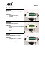
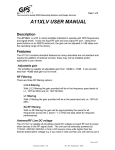
Page 1 of 7
Your source for quality GNSS Networking Solutions and Design Services!
Contents Description ............................................................................................................................. 2 Features .................................................................................................................................. 2 Adjustable Attenuation ...................................................................................................... 2 RF Filtering ........................................................................................................................ 2 L1/L2 filtering ................................................................................................................ 2 L1 filtering ..................................................................................................................... 2 No RF filtering ............................................................................................................... 3 Antenna/RF Line DC voltage ............................................................................................ 3 Antenna Current Fault Detection (Ant Fault Detect) ......................................................... 3 Oscillation Detection (OSC Detect)................................................................................... 3 LCD Display ...................................................................................................................... 3 LCD Backlight ................................................................................................................... 3 Serial port control .............................................................................................................. 4 Operation................................................................................................................................ 4 Terminal Mode................................................................................................................... 4 Command Mode................................................................................................................. 4 LCD Display and Menu System ............................................................................................ 5 Menu Options..................................................................................................................... 6 Brightness ...................................................................................................................... 6 Attenuation ..................................................................................................................... 6 Contrast .......................................................................................................................... 6 Help ................................................................................................................................ 7 Antenna Power On Off .................................................................................................. 7 Antenna VDC................................................................................................................. 7 AT11DV USER MANUAL
Document number: 430
Rev. 002
9 JUL 08
Page 2 of 7
Your source for quality GNSS Networking Solutions and Design Services!
Description
The AT11XDV is a RF (L band) attenuator intended to operate with GPS
frequencies and signal levels. It has one input RF port and one output RF port.
Using front panel buttons or an RS232 serial port, the attenuation can be adjusted
in 1dB steps over the operating range of the device.
Features
The AT11XDV contains standard features but many described are not standard
and require the addition of optional circuitry; these may not be installed and/or
applicable to your device.
Adjustable Attenuation
The attenuator is capable of adjustable attenuation from 0dB to 55dB.
RF Filtering
There are three RF filtering options:
L1/L2 filtering
With L1L2 filtering, the attenuation range provided will be in the frequency
pass bands of L1, 1575.42 MHz and L2, 1227.5 MHz.
L1 filtering
With L1filtering, the attenuation range provided will be in the pass band
only, i.e., 1575.42 MHz.
Document number: 430
Rev. 002
9 JUL 08
Page 3 of 7
Your source for quality GNSS Networking Solutions and Design Services!
No RF filtering
With no RF filtering, the attenuation range will be approximately the same
for all frequencies across the L band (~ 1-2 GHZ see data sheet for
response performance).
Antenna/RF Line DC voltage
The AT11DV is capable of providing a fixed DC voltage out each RF port to power
other devices in the RF signal chain. The unit can be externally powered by
110VAC/220VAC/240VAC or from a DC source a few volts higher than the desired
antenna/line voltage, e.g., if you want 5 volts out then you will need to put in
approximately 8 VDC into the device to overcome the losses of reverse polarity
diodes, regulator losses, and diode output OR function.
Antenna Current Fault Detection (Ant Fault Detect)
If the antenna current exceeds either a high or low threshold value then the device
will remove power from the antenna or input port and will display an error message
on the display and via serial port.
After approximately 10 to 13 seconds, the unit will retry to see if the current fault
condition has been removed by clearing the error message and momentarily
reconnecting power to the input port. If a high or low threshold current level is no
longer exceeded then the device will once again operate normally. The exact
trigger level[s] can be set via the serial port.
(AT11_A11XLV_Serial_Interface_Reference)
If you do not have the serial port option, the factory defaults are low current
threshold levels less than 15ma and high threshold levels greater than 150ma.
Oscillation Detection (OSC Detect)
The AT11DV is capable of detecting high levels of RF indicative of feedback from
the device input to the output or a runaway condition. If the OSC Detect’s circuitry
threshold is exceeded, the unit will remove power from the antenna or input and
will display an error message on the display and via the serial port. The unit will
not retry and requires a key press or equivalent character[s] from the serial port to
clear the error and retry by restoring antenna power. The exact trigger level[s] can
be set via the serial port. (AT11DV_A11XLV_Serial_Interface_Reference)
If you do not order the serial port option, this level is preset at the factory.
LCD Display
The A11XLV can be equipped with a LCD display to provide feedback to the user.
LCD Backlight
The LCD display can be equipped with an LCD backlight. The backlight is only
available with the power supply option.
Document number: 430
Rev. 002
9 JUL 08
Page 4 of 7
Your source for quality GNSS Networking Solutions and Design Services!
Serial port control
The A11XLV can be controlled via an RS232 port.
Operation
In normal operation, the AT11DV is controlled via the front panel using buttons.
There are three buttons: UP, DOWN, and ENTER.
The unit can also be controlled via an RS232 port using a terminal emulator, either
in terminal mode or in command mode, programmatically.
Terminal Mode
Connection to the device is achieved by using either a standard terminal device or,
in a more likely scenario, a computer utilizing terminal emulation software, such as:
Hyperterm, Terra Term, Kermit etc.
The unit can be operated with computer keys in exactly the same manner as
pressing the buttons on the front panel of the device by navigating through the
menu with the up arrow, down arrow, and Enter key, or equivalent ESC
sequences. The device will echo the text to the serial port and, in most cases, will
equal or be more verbose to the front panel LCD.
Note: the letter “D” & “d” will also function as the down arrow key and the letter “U”
& “u” will function as the up arrow key.
The terminal ESC sequences ESC[B] or 0x1B and then a 0x41 will function as an
up arrow key.
The terminal ESC sequences ESC[A] or 0x1B and then a 0x41 will function as an
up arrow key.
(If there are any dinosaurs reading this, these are VT100 terminal escape
sequences)
Command Mode
In command mode, the unit can be controlled or operated by sending specific
commands as opposed to navigating menus via key strokes.
Though there is nothing stopping a user from sending individual key strokes, i.e.,
characters programmatically and navigating menus, it is neither needed nor
recommended.
A command set is provided to execute functions directly so the unit can be
controlled by a machine or computer as in an automatic test setup.
Document number: 430
Rev. 002
9 JUL 08
Page 5 of 7
Your source for quality GNSS Networking Solutions and Design Services!
See the AT11DV_A11XLV_Serial_Interface_Reference for a complete list of
commands.
LCD Display and Menu System
From the top level of the menu, each press of the up or down button navigates the
menu system. The menu system is flat, i.e., it is a loop of items that can be
selected for modification or selected to display the current values or settings. Once
an item is selected, the up and down button can be used to change the displayed
values of the particular item. After approximately 10 seconds with no user input
(button presses from the user or characters on the serial port), the menu returns to
the main screen and displays gain.
Document number: 430
Rev. 002
9 JUL 08
Page 6 of 7
Your source for quality GNSS Networking Solutions and Design Services!
Menu Options
Brightness
Sets the level of brightness of the LCD back
light.
Instructions
1. Press middle (down) button
2. Press ‘Enter’
3. Adjust brightness using up/down buttons
Attenuation
Sets attenuation of the device.
Instructions
1. Press up or down button until ‘Level’ appears
onscreen
2. Press ‘Enter’
3. Adjust gain level up or down using up/down
buttons
Contrast
Sets the contrast of the LCD display.
Instructions
1. Press middle (down) or up button until
‘Contrast’ is displayed on screen
2. Press ‘Enter’
3. Adjust contrast using up/down buttons
Document number: 430
Rev. 002
9 JUL 08
Page 7 of 7
Your source for quality GNSS Networking Solutions and Design Services!
Help
The Help menu displays the serial number
of the device, the version of the firmware,
and the URL of GPS Source for service and
support.
Instructions
1. Press middle (down) button until ‘Help’
appears on screen
2. Press ‘Enter’
3. View information specific to product by using
up/down arrows
Antenna Power On Off
The Antenna operation turns the antenna
power on and off.
Note: Antenna power is on the input port.
This action does not affect the output port,
so it will not turn off power to the devices
powered by the output port, provided the
output port is a pass DC (PDC) port.
Antenna VDC
Displays the voltage that is available to
power the output ports.
Note: This only displays the voltage
available to the ports. If a port is DCB (DC
blocked) then this does not mean there is
voltage present on the port. Only if a port is
enabled to pass DC (PDC) will the voltage
be available on the port[s]. No matter what
this reads, there will only be voltage on a
port if it is PDC.
Document number: 430
Rev. 002
9 JUL 08