1
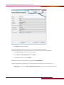
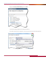
USING MENTOR EMBEDDED SOURCERY
PROBE TO PROGRAM FLASH DEVICES
E
M
B
E
D
D
E
D
S
O
F
T
W
A
R
E
‘H O W - T O’ W H I T E P A P E R
KATHLEEN OLIVER, TECHNICAL MARKETING ENGINEER
w w w.m e n t o r.c o m
Using Mentor Embedded Sourcery Probe to Program Flash Devices
INTRODUCTION
Use the flash programming utility to program NOR flash memory on your ARM or MIPS target system using
a Mentor® Embedded Sourcery™ Probe (MESP). The flash utility is downloaded to the target system using
Sourcery Probe and Mentor® Embedded Sourcery™ CodeBench and runs on the target system. It enables
you to erase and program NOR flash memory devices on the target through your JTAG port. This document
explains the steps to set up and use the flash programming utility.
Note that the Sourcery CodeBench Debug Sprite for ARM targets also supports programming of flash memory
on the target. When used with an appropriate linker script and board configuration, flash programming is
automatic when you load your program in the debugger. However, this does not allow you to erase devices,
but it does enable you to write only compiled applications, one at a time, to the target. The Flash Utility
enables you to both erase and program anything at any location on your flash device.
FLASH UTILITY: AN OVERVIEW
The Flash Utility is a program that is downloaded to and run on the target board using a MESP. It uses the
Semi-Hosting feature to do the following:
■■ Display flash configuration settings such as flash device type and base address
■■ Provide menus to control the flash settings and perform flash functions such as erase and program
■■ Read the flash image (binary) file over JTAG when programming or verifying the image
■■ Write the flash image to a file over JTAG when backing up the flash image to disk
NOTE: Since the Flash Utility runs from RAM on the target board, it must be possible to download it into RAM.
Usually this means the memory controller must be initialized prior to running the Flash Utility. If your board
has good working boot code, then it will perform this initialization. However, if there is no boot code (or bad
boot code) then you may need to use the MESP to initialize the memory controller. This is accomplished by
running a board initialization script. For more information, see the Sourcery Probe Target Initialization Scripts
topic in Chapter 2 of the Mentor Embedded Sourcery Probe User’s Manual.
WARNING: Before erasing the boot code on your board, make sure you have a suitable memory controller
initialization script or it may be very difficult to get back to the point where you can install new boot code.
GETTING STARTED
Since the Flash Utility runs on the target board, it is downloaded and run via a debugger. This section explains
how to set up the environment for running the Flash Utility using the Sourcery CodeBench IDE and MESP.
NOTE: This utility is compatible only with the Fall 2011 release of Sourcery CodeBench for ARM EABI and
Sourcery CodeBench for MIPS ELF.
PREREQUISITES
■■ A CodeBench board support file (CS3) for your target must exist, see Chapter 6 of the CodeBench Getting
Started manual for a list of supported boards. If your board is not on the list, use the CodeBench Board
Builder to create a custom board definition and linker scripts.
■■ A MESP initialization script for your target must exist. If one does not exist, refer to the MESP User Manual
for information on creating one.
w w w. m e nto r. co m
2
Using Mentor Embedded Sourcery Probe to Program Flash Devices
■■ You must run this utility in hosted mode on MIPS targets and semihosting mode on ARM targets.
PROCEDURE
1. Start Sourcery CodeBench.
2. Create a new, empty project for your target:
a. Select File > NEW > C Project. This opens the C Project wizard:
b. Enter project information and click Next:
c. Enter information about your target. NOTE: If your Board does not exist, use the Board Builder
to create a CS3 file for your target.
w w w. m e nto r. co m
3
Using Mentor Embedded Sourcery Probe to Program Flash Devices
d. Click Finish to create the project.
3. Import the Flash Utility source code (target_flash.c) into your project workspace:
TIP: Click target_flash.c above to downloaod the source or go to http://go.mentor.com/probeflash.
a. Select File > Import. This opens the Import wizard.
b. Select General > Existing Projects and click Next.
c. Select the file to import and click Finish.
4. To build the application, right-click the project and select Build Project.
5. Create a Debug Launch configuration so you can download the flash utility to your target run it:
a. Select your project and select Run > Debug Configurations. This opens the Debug Configurations
dialog box.
w w w. m e nto r. co m
4
Using Mentor Embedded Sourcery Probe to Program Flash Devices
b. Right-click Sourcery CodeBench Debug and select New.
c. Select the new debug configuration. This displays the Main tab.
d. In the Main tab of the launch configuration, select your project and select the flash utility application.
w w w. m e nto r. co m
5
Using Mentor Embedded Sourcery Probe to Program Flash Devices
e. Select the Debugger tab.
f. Set the Debug Interface to Sourcery Probe.
i. Enter the Hostname or IPADDRESS of your probe.
ii. Select your Board. This should Populate the Debugger Options for you.
Verify that they are correct.
iii. NOTE: You must run this utility in hosted mode on MIPS targets and semihosting
mode on ARM targets. These are the default options for MESP. Do not deselect them.
iv. Click Apply.
w w w. m e nto r. co m
6
Using Mentor Embedded Sourcery Probe to Program Flash Devices
6. Click Debug to download the flash utility to your target and run it. This opens the Debug perspective in the
CodeBench IDE. If you see the dialog box below, click Yes:
7. By default, the debugger stops at Main, click
to run the Flash Utility. The Flash Utility displays the flash
configuration settings similar to the ones below in the target_flash Debug console:
************************************************
Target Flash Programmer v3.1.4.1 - LE
Flash Device : AT49BV6416B x16 8MEG Boot Bottom
Devices : 1-Series 1-Parallel 1-Total
Sector Groups : 2
Sector Count : 8 127
Sector Size : 8K 64K (bytes)
Device Base : 0x10000000
Device Offset : 0x00000000
Device Buffer : 0 (bytes, max = 0)
************************************************
8. Configure your flash settings:
The flash configuration settings must be correct for the Flash Utility to work properly. The following
sections explain how to set the flash settings.
NOTE: If configuration file for your target exists in your workspace with the following name
targetflash_be.cfg (Big Endian) or targetflash_le.cfg (Little Endian), the Flash Utility will automatically
load it when it starts.
a. Make the Console that contains the Target Flash Programmer large enough to see everything.
b. Type 1 in the Console to set the Flash Device. First, it will ask for the flash part vendor, then, it will ask
for the flash device type. For some flash parts it will also ask for the device width (8 vs. 16 bit) and
sector organization (top vs. bottom boot mode). After you set the flash type, the Flash Utility will
display the new flash configuration settings so you can check. The Sector Groups, Sector Count,
and Sector Size fields should reflect the details of the part type that you selected.
c. Return to the Main menu.
d. Type 3 to set the Device Base Address and set it to the first address of the flash device.
e. Optionally, type 4 to set a Device Offset.
9. Type 10 to display the Configuration menu and then select 9 to save your configuration settings to a
file that you can load the next time you run the Flash Utility.
a. This creates targetflash_be.cfg (Big Endian) or targetflash_le.cfg (Little Endian) in your project
workspace.
b. Type 0 to return to the Main menu.
w w w. m e nto r. co m
7
Using Mentor Embedded Sourcery Probe to Program Flash Devices
10. Configure the Image Settings for the image that you will write to your flash device:
a. From the Main Menu, type 2 and enter the Image Filename of the image to write to your flash device.
b. Optionally, if you want to start programming part way through the file, instead of starting with the
first byte of the file, from the Main Menu, type 3 to specify a File Offset.
c. If you want to save your image settings, from the Main Menu, # Type 10 to display the Configuration
menu and type 9 to save your configuration settings to a file that you can load the next time you run the Flash Utility.
11. Use the Flash Utility to program, erase, and verify your device. For a list of operations see
Flash Utility Operations.
FLASH CONFIGURATION SETTINGS
Flash Device:
To set the Flash Device, select the Flash Type option (1) from the main menu. First, it will ask for the flash part
vendor, then, it will ask for the flash device type. For some flash parts it will also ask for the device width (8 vs.
16 bit) and sector organization (top vs. bottom boot mode). After you set the flash type, the Flash Utility will
display the new flash configuration settings so you can check. The Sector Groups, Sector Count, and Sector
Size fields should reflect the details of the part type that you selected.
Multiple Devices:
If your board has two flash devices of the same type connected in series or in parallel, the Flash Utility can
operate on them together. You can select two in a series or two in parallel via the Flash Device menu.
NOTE:
- They are connected in parallel if they occupy different byte lanes on the data bus and can be
accessed simultaneously.
- They are connected in series if they are connected to the same byte lane(s), and the first address
of the second part comes immediately after the last address of the first device.
Device Buffer:
Many newer flash devices provide a write buffer to faster programming. When you select the flash device the
Flash Utility sets the Device Buffer to the size of the write buffer for that part, or 0 if the part has no write
buffer. During flash programming, the Flash Utility uses buffered write mode if the device buffer is non-zero,
or normal write mode if the device buffer is zero. If you experience trouble programming a part, but you are
able to erase it, then you may need to change the device buffer size in the Flash Device menu.
Device Base:
Set the Device Base should to the first address of the flash device, no matter whether you want to program all
or just part of your flash device. This can be set from the main menu.
Device Offset:
The Device Offset should normally be 0, unless your flash image will only occupy upper sectors of the flash
part and you do not want to erase or program the lower sectors.
w w w. m e nto r. co m
8
Using Mentor Embedded Sourcery Probe to Program Flash Devices
IMAGE SETTINGS
After displaying the flash settings, the Flash Utility displays the image settings:
**********************************************
Filename : test.bin
File Offset : 0 (0x00000000)
File Length : 0 (0x00000000)
Image Size : 0 (0x00000000)
Image Address : 0x10000000
Image Buffer : 0x00800000 (bytes, Enabled)
***********************************************
Image Filename:
The Filename is the file to program into the flash part(s). To specify the image filename, including the path to
the file, select the Image Filename option in the main menu.
- File Length
The File Length field is automatically set when you choose the image filename, and you can not change it (except by choosing a different file).
- Image Size
Normally the Image Size should be set to match the file length, but you can use that setting to constrain the amount of flash being programmed if upper sections need to be preserved, or to operate on the entire flash instead of just the part corresponding to the image file. To set the image size, select the Image Size option in the main menu.
- Image Address
The Image Address field shows the range of flash memory that is occupied by the selected image size. The start address is the Device Base address plus Device Offset, the end of the range is the start address plus the image size (the end address is not shown if the image size is 0).
File Offset:
The File Offset field allows you to start programming part way through the file, instead of starting with the
first byte of the file. For example, you could skip over a header that was prepended to the file. Normally this
option should be set to 0.
Image Buffer:
This is an advanced setting that is optional. It allows a copy of the image file to be saved locally when the
device is programmed, so the program verify operation can complete faster. If your target has at least twice as
much RAM as flash, and you are programming a large flash image, then you might want to enable the image
buffer.
w w w. m e nto r. co m
9
Using Mentor Embedded Sourcery Probe to Program Flash Devices
To set up an image buffer, select the Configuration menu and select Image Buffer to display the following
menu:
***************************************
IMAGE BUFFER MENU
1) Enable Image Buffer
2) Use malloc For Image Buffer
3) Image Buffer Size
4) Image Buffer Address
5) Test Image Buffer Memory
****************************************
First, set the Image Buffer Size to the flash device size (or total size, if you have multiple devices). For MIPS
targets, set the Image Buffer Address to 1Meg above the start of your RAM area. For ARM and XScale targets,
chose the option to Use malloc For Image Buffer. Then, enable the image buffer and optionally test it.
FLASH UTILITY OPERATIONS
Erasing:
Use the Erase menu to erase part, or all, of the device, to verify that the area or device is erased, or to search
for erased and programmed sections. The Erase Device option erases every sector of your flash part(s). The
Erase Image Sector(s) option erases the sectors corresponding to the image address.
Programming:
Use the Program menu to back up the flash part to a file, to program the image file into flash, or to search
for programmed sections. This menu also provides options to erase the whole device or the sectors
corresponding to the image address prior to programming the selected file.
- Special Modes
Some target boards require special programming modes. For example, it may be necessary
to XOR the address with 2 or 3 to ensure the flash command bytes are routed to the data bus
byte lanes that are used by the flash device(s). This is a function of the processor’s bus interface
and endian mode of your memory system.
NOTE:
- If your target requires special handling of address bits 1..0, set the XOR option accordingly
via the XOR Address option in the Program menu. Please refer to your processor documentation
for more information about this potential requirement.
- It may also be desirable to byte-swap the image being programmed, backed up (saved from flash to a file), or verified. Byte swapping may be set using the Swap options in the Program menu.
w w w. m e nto r. co m
10
Using Mentor Embedded Sourcery Probe to Program Flash Devices
Diagnostic Menu:
Use the Diagnostic menu if you need to test the special modes listed above or if you need to check basic
flash functionality.
Timeouts:
Flash operations such as erase and program are performed by writing a command to the flash part, then
polling the flash part for status. Most flash operations take much longer to complete than the single bus cycle
that it takes to initiate them, so polling for status is how the Flash Utility determines when it can advance to
the next operation. If there is some problem with the hardware, the flash operation might never be able to
complete, so the Flash Utility employs a timeout mechanism to abort if it appears that an operation will not
complete.
However, since the Flash Utility is a generic program meant to run on any target that has sufficient RAM, it
does not have a real time base to use for the timeout. Instead, it uses a large loop counter, which means the
actual timeout period is a function of the speed of the processor. On particularly fast processors the timeout
may occur too soon even though the flash operation would eventually complete. In this case, you can increase
the timeout period for the various flash operations using the Configuration menu.
For additional information, please visit: mentor.com/embedded
For the latest product information, call us or visit:
w w w.m e n t o r.c o m
©2011 Mentor Graphics Corporation, all rights reserved. This document contains information that is proprietary to Mentor Graphics Corporation and
may be duplicated in whole or in part by the original recipient for internal business purposes only, provided that this entire notice appears in all copies.
In accepting this document, the recipient agrees to make every reasonable effort to prevent unauthorized use of this information. All trademarks
mentioned in this document are the trademarks of their respective owners.
MGC 12-11
TECH 10430w