1
MV electrical network management
Easergy range
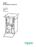
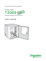
T200S
Automation and control unit for SM6
User's manual
Easergy T200 S
1
Summary
GENERAL DESCRIPTION ................................................................................................
................................
.......................................................... 3
1.1 INTRODUCTION ................................................................................................................................
................................
.............................................3
1.2 DESCRIPTION ................................................................................................................................
................................
...............................................4
1.3 T200S BLOCK DIAGRAM ................................................................................................
................................
................................................................5
2
INSTALLATION AND CONNECTIONS ................................................................................................
....................................... 6
2.1
2.2
2.3
2.4
2.5
2.6
2.7
2.8
3
2 CHANNEL CPU CARD................................................................................................
................................
..................................................................7
CONNECTION TO THE SWITCH ................................................................................................
................................
........................................................8
CTS CONNECTION ................................................................................................................................
................................
.........................................8
CONNECTING THE VD23 VOLTAGE RELAYS................................................................................................
.....................................9
CONNECTION TO THE GENSET ................................................................................................
................................
.......................................................9
CT INSTALLATION................................................................................................................................
................................
..........................................9
REMOTE TRANSMISSION EQUIPMENT
QUIPMENT ................................................................................................
............................................10
POWER SUPPLY ................................................................................................................................
................................
..........................................13
CONNECTION TO THE T200 ................................................................................................
................................
....................................................14
3.1
3.2
3.3
3.4
3.5
4
STEP 1 - INSTALLING JAVA RUNTIME ENVIRONMENT 5.0 ................................................................
...............................................15
STEP 2 - INSTALLING THE USB DRIVER ................................................................................................
........................................16
STEP 3 – CREATION OF THE PSTN OR GSM REMOTE NETWORK CONNECTION...............................................17
................................
STEP 4 – STARTING CONNECTION WITH
W
THE T200 ................................................................
........................................................18
OVERVIEW OF THE EMBEDDED W EB SERVER OF THE T200................................................................
............................................22
T200 SETTINGS ................................................................................................................................
................................
........................................27
4.1 COMMENT AREA : ................................................................................................................................
................................
........................................28
4.2 CONFIGURATION OF SNTP SERVICE ................................................................................................
............................................29
4.3 CONFIGURATION OF ETHERNET INTERFACES ................................................................
................................................................30
4.4 SAVE/RESTORE CONFIGURATION PARAMETERS ................................................................
............................................................31
4.5 PARAMETERS FOR COMMUNICATION
ICATION WITH THE
T
SUPERVISOR ................................................................
..........................................32
4.6 SWITCH CONTROL PARAMETERS ................................................................................................
................................
..................................................48
4.7 PARAMETERS OF THE VARIOUS
IOUS OPTIONS ................................................................................................
......................................51
4.8 AUTOMATIC CONTROL PARAMETERS
AMETERS ................................................................................................
............................................53
4.9 PARAMETERS OF THE FAULT
LT DETECTION MODULE ................................................................
.........................................................56
4.10 CUSTOMIZATION OF T200 VARIABLES ................................................................................................
......................................60
4.11 CUSTOMIZATION OF T200 CLASSES................................................................................................
.........................................73
4.12 TESTS AT COMMISSIONING ................................................................................................
................................
......................................................74
5
OPERATION ................................................................................................................................
................................
..............................................75
5.1
5.2
5.3
5.4
6
OPERATING MODE................................................................................................................................
................................
.......................................75
SWITCH CONTROL ................................................................................................................................
................................
.......................................76
OTHER ORDERS ................................................................................................................................
................................
..........................................76
TESTING OF INDICATOR LAMPS AND FAULT DETECTION
DETE
................................................................
..................................................76
MAINTENANCE ................................................................................................................................
................................
.........................................77
6.1 DIAGNOSTICS VIA THE FRONT
RONT PANEL INDICATOR LAMPS AND LOGS .................................................................78
................................
6.2 POWER SUPPLIES ................................................................................................................................
................................
.......................................81
6.3 CARD REPLACEMENT ................................................................................................
................................
..................................................................82
7
APPENDIX A – CONFIGURABLE PARAMETERS
PARAMET
................................................................
..................................................83
8
APPENDIX B - GENERAL CHARACTERISTICS
CHARACTERIST
................................................................
.....................................................91
2
NT00243-EN-03
Overview
General description
1 General description
1.1 Introduction
Easergy T200 S is a range of autochangeover automation and telecontrol interface
dedicated to SM6 range of switchgears.
Type IM cubicles allow two IM cubicles without automated changeover to be
remote controlled.
Type NSM cubicles are supplied in one of two versions: either with a two network
source
ce changeover switch or with a network channel changeover switch on a
genset channel (genset control is an option for the T200S).
Functions performed by the equipment:
Management of MV switch opening/closing electric control
unit
The control is triggered by actuation from the control station, by local operator
control, or by internal automatic controls.
Measurement acquisition and processing
The T200 S can incorporate the following measurements and processing functions:
For each channel:
Current measurement
ent on each phase;
Calculation of the average load current;
Residual current measurement;
Monitoring, for the purposes of remote indication and/or local
display, of MV substation and Easergy T200 information:
Open/closed position of MV switch;
“Locked” state of MV switch;
Phase-to-phase or phase-to-earth
earth fault current detection;
Voltage present;
Automatic control ON/OFF position;
Local/remote operating mode;
Immediate alternating supply voltage failure;
Time-delayed
delayed alternating supply voltage failure;
Charger fault;
Battery fault;
External 12 V power supply failure;
Motorization supply voltage failure.
Logs
stamped chronological logging of events and measurements.
Time-stamped
This information can be transmitted to the control centre and archived in logs for
consultation and local downloading (in file form), by connection of a microcomputer.
Automatic controls
ATS (Automatic Transfer of Source): Automatic source changeover upon
voltage loss detected on one of the channels.
Backup power supply
For all the control
trol unit components, the transmission equipment and the switch
motorization with a battery life of several hours in the event of an AC supply outage.
Local communication or communication with the remote
control centre
One communication ports is available for remote communication with the
control centre. This port use either modem integrated in the COM card or
external equipment managed by the rack serial link.
A choice of modem allowing any type of mounting:
Radio (600/1200 baud FSK or 1200/2400 FFSK);
PSTN isolated at 8 kV (300 to 14400 bits/s -V32 bis);
GSM / GPRS (quad-band version 900/1800/850/1900
/1800/850/1900 MHz), SIM card
accessible on the front panel
GSM / 3G - UMTS & HSPA+ (3,75G), EDGE, GRPS & GSM. Quad-band
Quad
modem in GSM (900/1800/850/1900 MHz) and five band
ba in 3G
(800/850/AWS/1900/2100 MHz), SIM card accessible on the front panel
RS232 or RS485 isolated at 2 kV (19200 baud).
Note: In an RS232 link, the port is replaced by the RS232 port integral with the
COM card and accessible via the RJ45 connector on the
t right of the rack.
In the case of the other transmission options, the modem is connected directly to
the front panel of the COM card.
NT00243-EN-03
3
Overview
General description
A catalogue of communication protocols for communication with the control
centre :
♦ IEC 870-5-101
♦ IEC 870-5-104
♦ DNP3, DNP3 / IP
♦ Modbus, Modbus / IP
An Ethernet communication port is available for communication with the
control centre or for access from the local PC for consultation/configuration.
This port is accessible on the front of the COM card.
A USB communication port is available for communication with the local PC
for consultation/configuration. This port is accessible on the front of the COM
card.
Time synchronization of the equipment
Time setting for event dating can be performed:
by the laptop PC for consultation/configuration of the T200 (manually or
automatically via the PC time);
by the control centre (if the protocol permits);
by SNTP sync (option) from an Ethernet network. The precision of time setting
is in this case approximately one second.
Calculation formulae
T200S NSM réseau
The calculation formulae are a standard
andard feature of the T200.
They can be used in the T200 to create new customized functions or applications
not requiring writing of a program in PLC language.
The functions that can be used in the formulae are:
- Mathematical functions;
- Statistical functions;
- Logical functions;
- Time/date functions;
- etc.
These formulae make it possible, more easily than with a PLC program, to create
logic equations based on combinations of variables. The types of variables that
can be used are the same as for PLC
C programs (existing T200 variables or virtual
variables created specifically). This inter--equipment communication is typically
used in applications of the self-healing
healing network type.
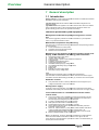
1.2 Description
Its main parts are:
T200S NSM Groupe
Identification
a rack gathering all electronic modules,
a grid to support the transmission equipment (radio, external modem…),
a battery providing a backup power supply when the enclosure is no longer
powered by the AC supply,
a “connection” part with:
two 9 pins plugs for connection to the switch,
two 4 pins plugs for the connection to the toroid sensors,
a lever type fuse holder for the AC power supply,
eventually, a terminal block to connect the emergency generator.
The rack contains three functional modules
modu
:
The Control module (marked CONTROL)
CONTROL
The Control module comprises a control panel (front panel) and a Central
Processing Unit (CPU) card.
It manages the functions of the 2 switches and controls local operation, with the
exception of communications. This module gets on the front plate the configuration
plug for automation and fault detectors.
The Communication module (marked COM)
It controls all the communications with the remote control centre via the modem.
The Power supply module (marked POWER)
It supplies power to the enclosure, the battery charger and the associated selfmonitoring equipment.
The serial number of the enclosure is formed as follows :
Serial number (e.g.: 0932 043002 001 008):
0932 = Year + Week of manufacture
043002 = Job number
001 = Delivery voucher line number
008 = Enclosure number manufactured for this order
4
NT00243-EN-03
Overview
General description
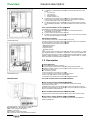
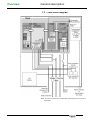
1.3 T200S block diagram
Note:: The various modules are connected via a “rack backplane card” not shown in
this diagram.
NT00243-EN-03
5
Installation
Installation and connections
2 Installation and connections
The T200S enclosure is prewired at the factory.
The connections to the CTs and switches are already installed.
Nevertheless, a few connections still need to be made:
- Connection to the control unit,
- Connection to the interface with the genset,
- Connection of transmission devices,
- Connection of the 230 Vac main supply,
- Connection of the battery,
- Powering up the unit.
Details of these connections are given in the sections below.
6
NT00243-EN-03
Installation
Connecting the CPU card
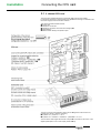
2.1 2 channel CPU card
The CPU card is located behind the control panel (front of the Control module).
It controls the equipment’s overall operation and permits the exchange of information with
the Power Supply and Communication modules.
This card incorporates several functions:
Control CPU
Interface for connection
Interface for the switch and current and voltage inputs
Fault detection
Measurements relating to acquisition inputs.
The type of current input acquisition chosen can be configured for each channel via
jumpers (W2: channel 1 and W3: channel 2):
3 phases CTs : position A = I1, I2, I3
2 phases CTs + residual or 1 residual CT : position B/C = I1, I3, I0.
The Connection card integral with the CPU card permits connection to the switch, to the
digital inputs/outputs, to the current inputs (toroid sensors).
NT00243-EN-03
7
Installation
Connecting the switch and CTs
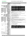
2.2 Connection to the switch
The following are factory wired:
Marking on the 9 pin MATE N LOCK connector from the rack
Connector pin
Marking
Function
1
0V
2
CC
Channel
hannel closing control
3
OC
Channel
hannel opening control
4
O
Open position
5
C
Closed position
osition
6
+
+V
7
Not used
8
PT
MV presence
esence
9
ET
Switch locked
Control polarity
The switches are controlled via a relay contact inside the T200 S enclosure.
Depending on the position of the fuse on the Control module, the switch motorization can
be controlled :
From the T200 internal power supply by a +V or 0V polarity.
polarity
From an external power supply.
Caution: for the T200S, the fuse must be set for a +V internal power supply.
The standard voltage of the internal power supply is 48V.
48
Connection of digital inputs DI
Digital inputs are available on special connectors “DI 1 to 4” and “DI 5 to 8”, accessible on
the Connection card under the rack on the left.
Note: the “DIs” are available spares.
Connection of digital outputs DO
3 digital outputs are also available on a special “DO” connector accessible on the
Connection card under the rack on the left.
DO assignment:
DO1: internal equipment fault synthesis. If an internal fault is present, the relay contact
closes and the yellow maintenance indicator lights up on the "Control" module.
DO2: Free or configurable option that can be activated when the MV line current
exceeds the fault detection phase or earth fault current threshold (see "Parameters
"
of the
various options" to activate this option via the software configuration).
DO3: Free.
Other connections (wired in factory)
0 V/+12 V outputs:: internal control of the genset startup/shutdown control relays. Outputs
controlled by the genset automatic transfer system (ATS) only.
2.3 CTs connection
The following are factory wired:
Marking on the 4 pin MATE N LOCK connector coming from the rack
Connector pin
Marking
Function
1
I1
Courant phase 1
2
I2 ou IH
Courant phase 2 ou homopolaire
3
I3
Courant phase 3
4
COM
Commun
Note: the earth CT (if used) must always be connected to phase 2.
8
NT00243-EN-03
Installation
Other connections
2.4 Connecting the VD23 voltage relays
If a source changeover automation system is used, a VD23 relay must be installed in the
cubicle to detect the presence of medium voltage from the signals emitted by the voltage
presence indicating system (VPIS). This relay monitors the voltage on the 3 phases, as
well as the voltage unbalance.
The "R1" output of this voltage relay must be connected to the cubicle connection cable as
shown opposite.
Note 1: in the case of the Genset ATS automatic transfer system, the voltage present on
the genset can also be acquired via the terminal block connected to the genset (see
below). The choice of acquisition is determined by software configuration (see chapter
"Automatic control parameters").
Note 2: the "source changeover" operation also requires an automatic transfer system
(ATS) lock to be wired (see chapter "Automatic
Automatic control parameters").
parameters
2.5 Connection to the Genset
If a changeover automation system controlling a genset (Genset ATS) is used, the genset
is connected as follows:
Voltage: dry contact closed if the genset has started up; to be wired to the two available
terminals (do not wire if voltage presence is detected by a VD23 relay)
Startup: genset startup order (dry contact),, to be wired to terminals C and B
Shutdown: genset shutdown order (dry contact),, to be wired to terminals D and B.
Note: voltage presence on a channel controlling the genset can also be detected by a
VD23 voltage relay (see above).
Terminal
Voltage
Mark
Start-up relay
C
D
B
A
C
D
B
A
Stop relay
Function
Generator started; generator voltage present
Generator started; generator voltage present
Start generator order
Free
Start generator order
Free
Free
Stop generator order
Stop generator order
Free
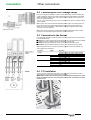
2.6 CT installation
The CTs must be mounted the same side up, the cables being oriented to the bottom :
Tag HAUT/TOP up above, wire outputs down (see below).
IMPORTANT: the MV cable earthing braid must be fitted back through the CT, before
being connected to the earth. The green/yellow wire must be connected to the same
earth as the CT.
NT00243-EN-03
9
Installation
Remote transmission equipments
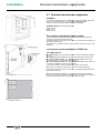
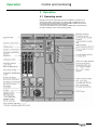
2.7 Remote transmission equipment
e
Location
A transmission interface slot (LL or RS485/232, modem, optical fibre cable, radio
and so on) is provided at the top right-hand
hand side of Easergy T200 P.
A slide-mounted support
upport offers various adjustment possibilities.
Available space (see illustration opposite)
Height: 240 mm
Width: 60 mm
Depth: 230 mm.
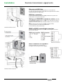
Transmission equipment power supply
The 12 Vdc supply for the remote transmission equipment is provided via the
connector on the right-hand
hand side of the rack.
The RS232 serial link is provided on the RJ45 8-pin
8
connector also located on the
right-hand side of the rack.
pin connector located on the front of the
The Radio link is provided on the RJ45 8-pin
COM card.
Transmission ports available on COM card
The COM card has :
An Ethernet link (connector RJ45) available on the front panel at the height of
slot S1.
An USB link (type B) available on the front panel also at the height of slot S1.
S1
A communication channel no. 1: RS232 serial link available on an RJ45
connector located on the right-hand side of the rack or.
A communication channel no. 2: customizable link (PSTN, radio, GSM, etc.)
if a modem is installed on slot S2 of the COM card.
In this case, the Modem output is available on the front of the channel.
Note 1: the two channels of transmission cannot be used simultaneously.
Iff a modem is installed in position S2, channel 1 is automatically deactivated and
replaced with channel 2.
Note 2 : communication channels no. 1 and 2 allow interfacing with external
transmission equipment (modems,
ems, interfaces, radios, etc.) that can be installed on
the sliding support grid located on the right-hand
hand side of the rack.
10
NT00243-EN-03
Installation
Remote transmission equipments
Ethernet and USB links
The USB and Ethernet links are available on the front of the COM card.
For linking with these transmission modes, the T200 complies with the connection
standard used (RJ45 and USB type B).
PSTN line connection
Connect the PSTN line to the terminals blocks provided for the purpose in the
PSTN modem on front panel of COM card.
Setting up a GSM/GPRS or GSM/3G modem (internal)
The GSM/GPRS or GSM/3G modem is installed on the COM card of the T200 on
one of the modem slots (no. 2).
The antenna connector and the SIM card are accessible on the front of the COM
card.
Attach the antenna to the wall of the substation (preferably outside).
outside)
Connect the antenna to the modem antenna connector.
connector
Insert the SIM card (T200 powered down).
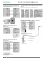
T200S with PSTN line access
RS485 or RS422 connection to supervisor
Connect the RS485 or RS422 line in accordance with the diagram of the RJ45
type connector opposite.
RS232 connection to supervisor
Connect the RS232 line in accordance with
the diagram of the RJ45 type connector opposite.
T200S with GSM or 3G access
NT00243-EN-03
11
Installation
Remote transmission equipments
Connecting to an analogue radio transceiver
(accessible on the RJ45 connector on the front of the internal
radio modem of the COM card)
Connection of RS232 external modem (PSTN, radio modem,
GSM, etc.)
(accessible on the RJ45 8-pin
pin connector on the right of the rack)
Example of connection with a Motorola
GM340 analogue radio
Example of connection with an MDS 4710 digital radio
(cord pre-wired in factory: CB00168)
Example of connection with a TAIT 811x
analogue radio
(cord pre-wired in factory: CB00121)
Example of connection with a TAIT 811x
analogue radio
(cord pre-wired in factory: CB00121)
12
NT00243-EN-03
Installation
Power supply
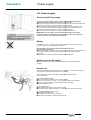
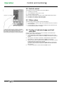
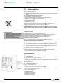
2.8 Power supply
Connecting 230 Vca supply
To prevent any risk of electric shock or burns, check that the mains supply is
disconnected before carrying out any work on the enclosure.
Switch off the supply circuit by moving the central lever on the safety fuse located in the
centre to the down position. It is not necessary to remove the fuse.
Connect the main power cable “AC supply” (2 x 2.5 mm2 into the appropriate cable
gland and connect it using the shortest possible length of cable of the bottom screw
terminals on the safety fuse (phase on the right, neutral on the left).
Check that the mains connector is correctly connected under the rack.
T: the “AC supply” input is insulated at 10 kV with respect to the
IMPORTANT:
enclosure earth. It is important to ensure that the cable and its use outside and
inside the enclosure do not damage this insulation.
Battery
The battery is of 12 V - 24 Ah type. It is housed in the lower left part of the enclosure.
It is held in position by a strap with tightening buckle.
ote: the battery must only be connected to the enclosure when
Note:
the equipment is powered up.
Connect the battery to the equipment by plugging the connector into the base under the
power supply module (the arrow on the connector must remain visible during the
connection).
The connector is polarized. DO NOT FORCE IT INTO POSITION.
Switching on the AC supply
Close the safety fuse inside the enclosure to power up the unit (see illustration
opposite).
Normal use
When the operations described above have been performed, the normal power supply to
the equipment is resumed and the battery can be charged.
When all the tests have been completed, the “Normal
Normal” status is as follows
(on the front panel):
On the Power supply module:
the “AC supply off” and “Battery fault” indicators are off,
the “Rack 12 V present”, and “Ext. 12 V ext. present” indicators are lit steadily,
the “48 V present” indicators
icators is lit steadily (after a 20 s time delay),
the fault indicators are off.
On the control module:
the “Local/Remote” switch is set to “Remote” mode”,
the indicator lamps reflect the indications, in particular the position of the cubicles.
On the Communication module (if any):
the “ON” indicator lamp is lit,
the “defect” indicator lamp goes off quickly,
the other communication indicator lamps remain off.
NT00243-EN-03
13
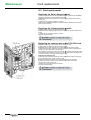
Connection to the T200
Initialization of connection
3 Connection to the T200
Easergy T200 S must be configured from a configuration PC. This is
performed from the COM card (single access). It allows configuration of:
The parameters of the CPU card (date, fault detection, etc.).
The parameters of the Communication card (com. parameters, alarms,
etc.).
The system parameters (variable management, class management,
etc.).
Equipment required for T200 connection
For testing-maintenance
maintenance configuration, the T200 requires:
A microcomputer operating under Windows 2000 or XP or Seven and
including Internet Explorer (version 5.5 or 6.0,
6.0 7, 8 or 9).
An USB port on this PC to perform connection with the T200.
An Ethernet port (RJ45) is available on the COM card for remote access to
the T200 from an Ethernet network.
This port can also be used for direct connection of the T200 with
w the PC.
The Ethernet cable required for Ethernet network-T200
network
connection or PCEthernet network connection is of the “straight--through” type.
The Ethernet cable required for PC-T200
T200 connection is of the “cross-over”
“cross
type.
The USB cable required for PC-T200
T200 connection is of the USB-A
USB type at one
end and USB-B at the other.
A CD-ROM is supplied to the user for:
Installation of the USB driver for connection with the T200.
Installation of Java Runtime Environment 5.0 needed for port trace
operation (Supervisor-T200 frame analysis).
NB: TCP/IP ports 1168, 1169 and 1170 must be accessible on the PC
for trace operation. Contact the network administrator if it is necessary to
alter the PC or network configuration to deactivate the firewall on these ports.
Configuration of the T200 is performed directly from Internet Explorer.
No other additional software is needed to access the T200 testingtesting
maintenance configuration operations (apart from Java Runtime 1.5).
Principle of the T200 embedded server
Type
B connector
USB cable
Type A connector
through” Ethernet cable
“Cross-over” or “straight-through”
depending on type of link access
The T200 includes an embedded server which is initialized automatically as
soon as connection is established with the T200.
The data displayed by the T200 through this embedded server appears in the
form of HTML pages.
pages can be accessed by the user depending on
Various pages and sub-pages
the rights available to him. The HTML pages displaying the information
managed by the T200 are refreshed in real time so as to update the latest
states.
Access and connection are secured by a Login and password. Several levels
of access
ess to the HTML pages can be configured, provided one have the
required rights.
From the embedded server, it is possible to:
Configure the fault detector, communications and automatic control
parameters or system parameters (management of variables, classes,
classe
rights, etc.);
View the states managed by the T200 (TSS, TSD, routine faults,
telemeasurements, etc.);
Save or load the T200 parameter configuration from files already
backed up on the PC;
Send remote control orders to the T200;
Transfer diagnostic logs in the form of Excel-compatible
Excel
files;
Load a new software version of the T200 application.
The embedded server can be accessed both by the USB port and by the
Ethernet port. There is no difference in operation according to the type of port
used.
Initialization
ization of connection to the T200
The T200 incorporates by default IP addresses necessary for local
connection from a PC. It is important to know these addresses in advance in
order to start a connection (these addresses are indicated on the Com card):
USB port: default address on the T200 = 212.1.1.10
Ethernet port: default address on the T200 = 172.16.0.5
Note: The USB address cannot be modified by the user. The Ethernet
address, on the other hand, can be modified (if the rights so permit) so as to
correspond to the local area network, which does not necessarily use the
same network addresses and masks.
For the T200 link via Ethernet, steps 2 and 3 are not necessary. In that case,
go directly to step 4.
14
NT00243-EN-03
Connection to the T200
Initialization of connection
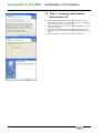
3.1 Step 1 - Installing Java Runtime
Environment 5.0
NT00243-EN-03
Insert the CD-ROM
ROM supplied with the T200 into the PC drive, then
double-click on the “jre-1_5_0_11-windows
windows-i586-p-s.exe” installation file
on the CD-ROM (in folder : "D:\Tools\Java
Java").
Software installation begins; click on the “Standard installation…" option
and then on “Accept”.
If new screen including Google options installation, deselect the two
proposed options "Google Toolbar" and "Google
Google Desktop",
Desktop then click on
"Next".
Wait until installation is completed, then click on “Terminate”.
15
Connection to the T200
Initialization of connection
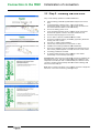
3.2 Step 2 - Installing the USB driver
Carry out the following operations to install the USB driver:
Insert the Easergy CD-ROM
ROM supplied with the equipment into the PC
drive.
A "Gamme Easergy / Easergy range – Vx.xx"
Vx.xx window should
automatically appear on screen. If this is not the case, double-click
double
on
the "Autorun.hta"" file located in the CD root directory.
Click on the "Easergy series 3" link.
Choose the setup language, then click on "ok".
Then click on "Install" to start installation.
The Easergy USB driver is installed.
In the "Equipements Easergy seriess 3 / Easergy series 3 Equipment"
Equipment
window which appears on screen, click on the "USB
"
Driver" link.
Click on "Next" to start the "InstallShield Wizard" module.
Choose the installation directory (the directory proposed
pr
by default can
be kept), then click on "Next".
A driver setup window appears on screen; click on "Next".
"
Installation of the Easergy USB driver starts automatically.
At the end of installation, when the window showing that the driver has
been correctly installed appears on screen, click on the "Finish"
"
button.
An "Easergy USB connection" start-up
up shortcut is also created
automatically on the PC desktop (see step 4).
Important note: Unlike the previous USB driver, this driver is installed for all
the USB ports of the PC. This driver needs therefore be installed only once,
irrespective of the USB port used. If a different USB port is used for a future
connection, Windowss will automatically detect and install the Easergy USB
driver for this other USB port.
Note: Step 2 is therefore necessary only for the first connection to equipment
with the PC. For a future connection, go directly to step 4.
16
NT00243-EN-03
Connection to the T200
Initialization of connection
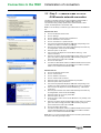
3.3 Step 3 – Creation of the PSTN or
GSM remote network connection
This step is to be taken into account only if the T200 includes a GSM or
PSTN (telephone) internal modem installed on the COM card.
This connection may possibly operate with an external PSTN or GSM
modem, but that depends on the modem used.
Note: It is not necessary to create this type of connection for the GPRS/3G
GPRS
link.
With Windows 2000
Click on the Windows “Start” button.
Enter the phone number of the T200 to be contacted (this number may
be changed later, at each connection attempt).
Select the option “For all users”.
When the connection window is displayed on screen, there is no need to
give a user name and login password, and if necessary change the
phone number of the T200 to be contacted.
Click on the “Dial” option.
Click on “Settings”.
Click on “Network connection and remote access”.
Click on “Establish a new connection”.
Click on "Connection
Connection to a private network".
network
From the list of peripherals displayed, select that corresponding to the
modem to be used for connection, by checking it.
Give a name to the telephone connection to the T200 (e.g. “T200
remote connection”).
The PSTN or GSM remote network connection between the PC and the
T200 is initialized between the two devices, then a modem connection
status icon is inserted in the Windows toolbar.
With Windows XP
Click on the Windows “Start” button.
Give a name to the telephone connection
n created (e.g. “T200 remote
connection”).
Enter the phone number of the T200 to be contacted (this number may
be changed later, at each connection attempt).
Select the option “Do
Do not use my smart card”.
card
When the connection window is displayed on screen, there is no need to
give a user name and login password, and if necessary change the
phone number of the T200 to be contacted.
Click on the option “Dial number”.
Click on “Control Panel”.
Click on “Network connections”.
Click on “Create a new connection”.
Select the option “Connect to the network at my workplace”.
workplace
Select the option “Dial-up connection”.
From the list of peripherals displayed, select that corresponding to the
modem to be used for telephone connection to the T200, by checking it.
Select the option “All users”.
Check the option “Add a shortcut to this connection to my desktop”,
desktop then
on “Terminate”.
The PSTN or GSM remote network connection between the PC and the
T200 is initialized between the two devices, then a modem connection
status icon is inserted in the Windows toolbar.
Note: Step 3 is no longer necessary after the first
f
connection performed with
the T200. In that case, go directly to step 4.
NT00243-EN-03
17
Connection to the T200
Initialization of connection
3.4 Step 4 – Starting connection with
the T200
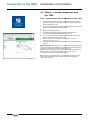
3.4.1 Local access via the USB port of the T200
The T200 being powered up without a “Fault” indicator lamp lit on the
COM card, connect the USB on one the USB port of the computer and
to the COM card of the unit.
Click on the "Easergy USB connection"" shortcut already installed on the
desktop of the PC to
o start the USB connection.
connection
Define the language to be used.
After few seconds, Internet explorer starts automatically and is
connected to the default USB IP address "212.1.1.10".
The connection to the unit is established automatically and the home
page of the Web server appears on screen.
Enter a “User name” and a “Password” (by default: “Easergy”,
“Easergy”), then click on “Ok”.
Access to the HTML pages is activated according to the rights related to
this user.
IMPORTANT NOTE:: After powering up or a Reset of the T200, it is important
to wait for completion of initialization of the COM card before connecting the
USB cable, otherwise the connection is likely not to work.
When the T200 is powered up, the red “Fault” indicator lamp
lam should flash for
approximately 10 s and then stay lit steadily for 3 s before going out.
Only then is connection of the USB cable possible.
Note: contrary to the old USB driver, to stop the USB connection, you just
have to disconnect the USB cable. Windows will stop automatically the
current USB connection.
18
NT00243-EN-03
Connection to the T200
Initialization of connection
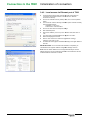
3.4.2 Local access via Ethernet port of T200
In the Windows Control Panel, click with the right mouse button on
"Connection to local area network" to be found in the "Network
Connections" directory.
Click on the "Internet Protocol (TCP/IP)" item, then on the "Properties"
button.
Then check the "Use the following IP address" option and then manually
enter the following items:
IP address = "172.16.0.3"
Subnet mask = "255.255.255.0".
Click on
n the "Ok" button to accept the settings.
The home page of the embedded server appears on screen.
Access to the HTML pages is activated according to the rights related to
this user.
Start Internet Explorer.
Enter the IP address (172.16.0.5) in the “Address” field, then click on
“Ok”.
Define the language to be used.
Enter a “User name” and a “Password” (by default: “Easergy”,
“Easergy”), then click on “Ok”.
IMPORTANT NOTE:: Once connection with the T200 is completed, you
should restore the original IP addresss configuration settings of the PC.
Note: there are useful utilities that can change automatically the TCP/IP
address of the PC. We recommend the software "Free IP Switcher" that can
be downloaded as a freeware on internet.
NT00243-EN-03
19
Connection to the T200
Initialization of connection
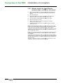
3.4.3 Remote access via a local Ethernet
network (LAN) or a GPRS or 3G network
With the T200 powered up, connect the PC and the T200 to the local
Ethernet network (LAN) using appropriate cables (straight Ethernet
cables).
Start Internet Explorer.
The home page of the embedded server appears on screen.
Access to the HTML pages is then activated according to the rights
related to this user.
Enter the IP address
dress of the T200 corresponding to the Ethernet or
GPRS/3G access in the “Address” field, then click on “Ok”.
Define the language to be used.
Enter a “User name” and a “Password” (by default: “Easergy”,
“Easergy”), then click on “Ok”.
Note: Generally the default IP address of the T200 cannot be used on the
Ethernet ,3G or GPRS network employed, and it must therefore be replaced,
in the T200's specific IP address configuration page, with an address
acceptable for the network (see section on IP address configuration). In that
case, the only way to access the T200's IP address configuration page is to
use the USB local connection.
Note 2: Unlike Ethernet access, the connection speed on a GPRS or 3G link
is relatively slow (max. theoretical connection speed for GPRS = 50Kbis/s,
3G = 2Mbits/s).
Accordingly, so that the display of data on screen may be slowed as little
l
as
possible, following a GPRS or 3G connection the T200 automatically displays
the pages of the Web server in simplified mode (Web server configuration in
"Remote" mode).
However, it is possible to return to a standard display by clicking on "Local"
configuration, at the top of the Web server home page.
20
NT00243-EN-03
Connection to the T200
Initialization of connection
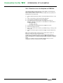
3.4.4 Remote access via telephone or GSM link
This access operates only when the T200 includes a GSM or PSTN (telephone)
internal modem installed on the COM card.
When an external modem is used, it is possible that this access may operate, but
that depends on the modem used.
Start the GSM-PSTN remote network connection
nection created previously (=> step
3).
Click on “Dial number” to start remote network connection.
The home page of the embedded server then appears on screen.
Access to the HTML pages is activated according to the rights related to this
user.
Once connection is established, start Internet Explorer.
In the address field of Internet Explorer, enter one of the following IP
addresses, depending on the port No. on which the RTC or GSM modem is
installed on the T200:
- For port 1: 212.1.0.1
- For port 2: 212.1.0.3
Define the language to be used.
Enter a “User name” and a “Password” (by default: “Easergy”, “Easergy”), then
click on “Ok”.
Note: Unlike a standard USB or Ethernet access, the connection speed on a
telephone or GSM link is rather slow (9600 baud).
Accordingly, so that the display of data on screen may be slowed as little as
possible, following a PSTN or GSM connection the T200 automatically displays the
pages of the Web server in simplified mode (Web server configuration in "Remote"
mode).
However, it is possible to return to a standard display by clicking on "Local"
configuration, at the top of the Web server home page.
NT00243-EN-03
21
Connection to the T200 Overview of the Web server
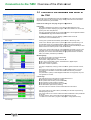
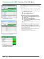
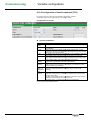
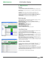
3.5 Overview of the embedded Web server of
the T200
Once access to the embedded server has been identified by user name and password,
all the HTML pages can be consulted by simply clicking on the tabs or the associated
drop-down lists when they are available:
Details of the settings for each page are given in Appendix A.
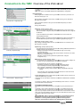
Home Page:
This page is displayed at connection to the T200. It enables definition of the
language to be used for displaying the pages. It also allows definition of user access
rights by user name and password.
The users and passwords that can be accessed depend on the configuration defined
in the Maintenance page and the Users sub-menu.
menu.
By default, the “Easergy”
Easergy” user and “Easergy” password allow access as
“Administrator” to the embedded server.
Home Page
A wrong user or password automatically opens access in “Monitoring” mode.
A click on the "Remote" option at the top of the page makes it possible to log on to
the
e T200 Web server with a simplified display of information (without images or
logos) so as to optimize data transfer times. This mode is used automatically for slow
remote network connections (PSTN or GSM at 9.6 Kbits/s).
A click on the "Local" button at the top of the page makes it possible to log on to the
T200 Web server with a normal display (all logos and images are transferred and
displayed). This mode is used automatically for high-speed
high
local area connections:
USB (115.2 Kbits/s) or Ethernet (100 Mbits/s).
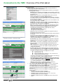
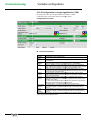
Monitoring Page:
This page can be used to consult the T200 states:
TSS: State of digital inputs, T200 i
nternal faults, voltage presences, current faults, etc.
TSD: open or closed state of switch, automatic control, digital outputs
TM: measurements of currents.
Counters: number of operations.
Monitoring Page
The page is displayed by class (e.g. State of channels, System, Automatic Control,
etc.).
Each class covers a category of information so as to facilitate viewing on screen.
The states of the indications or measurements are refreshed every 3 seconds
automatically.
The presentation, quantity of data displayed and content of this page may vary from
one application to another.
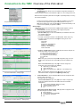
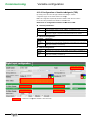
Control Page
This page allows local control orders to be sent from the PC to:
The switches (change of position by CO/CF);
The operation and counters (counter initialization);
The automatic controls (switching ON/OFF);
The digital outputs (forced setting open or closed);
The fault detector (fault memory resetting).
The T200 must be in "Remote" mode to be able to send control orders.
The control orders on the TSDs make it possible to go to the state complementing
that displayed by the T200.
The control orders on the counters enable them to be initialized at a value
valu predefined
by the user.
For safety reasons, each control order must be confirmed by the user.
The state of a control order in progress is displayed in orange (default colour).
Control Page
22
NT00243-EN-03
Connection to the T200 Overview of the Web server
The state of the control order is refreshed on screen automatically as soon as it is
completed.
Note: The colours of the states displayed can be modified by configuration.
Diagnostic Pages:
These pages allow consultation of the logs recorded in real time by the T200. The
event time stamping is 1 ms.
Drop-down list – Diagnostic page
Each log allows consultation of the history of states occurring on the T200 with a
description of the states.
All the information present in the logs is time-and
and-date stamped by the T200's
internal clock.
The logs are as follows:
•Alarm log: (storage capacity: 2000)
Alarms can be generated and transmitted spontaneously to the control centre
after an information change of state, provided that this state has been configured
as alarmed.
A box associated with each alarm is checked when the control centre has
acknowledged this alarm.
Note: Information configured as alarmed automatically implies the generation of
an associated event (in the event log or measures log depending on type).
•Event log: (storage capacity: 10000)
Every change of state generates an event, provided that the use of events for this
state has been configured.
Event log - Diagnostic page
•System log: (storage capacity: 6000)
The equipment also incorporates a function for recording additional information to
facilitate operation and maintenance.
- Storage of transmission events (to determine the origin of a recurring
communication fault);
ror, collisions, PSTN line out of order,
- Indication of transmission errors (CRC error,
switchover to redundancy, etc.);
up, T200 reset, change of
- Indication of system events (T200 start-up,
configuration, etc.).
•Measures log: (storage capacity: 30000)
The measurements managed by the T200 (phase current or
o mains voltage) can
be saved in a log, provided that their use has been configured.
The measurements can be recorded in several ways:
- Periodically (sampled or averaged value with configurable period);
- Upon exceeding a threshold (configurable high or low threshold);
- Upon variation or “dead band” (configurable variation %);
- Upon periodic recording of Min. and Max. values (configurable values and
period).
For all the logs, when the storage capacity is reached, the most recent event
occurring erases the oldest
st event on the list.
Files download – Diagnostic page
•A Files download sub-menu
menu allows these logs to be saved to the PC in the form of
Excel-compatible files (*.csv files).
These files can be consulted or transferred, to enable the establishment of statistics
or reviews.
An "Empty log" button in each log can be used to empty their content, i.e. to erase
all the information saved previously.
Principle of saving to logs:
To increase the life of the flash memory, saving to the logs is performed every 5
min.
Accordingly, when a reset is performed
rformed on the T200, it is possible that the most
recent events that have occurred since the last backup may not be saved in the
logs. The only exception is when imminent cut-out
out occurs on the enclosure. In that
case, even if the time elapsed is less than 5 min., the T200 saves the events to the
logs before cutting off the power supply.
ATTENTION : After a change of configuration, it is important to wait for
about fifteen seconds (the time needed for the equipment to store the
parameters in memory) before performing a reset on the equipment.
Otherwise, the equipment is likely to lose its configuration permanently.
NT00243-EN-03
23
Connection to the T200 Overview of the Web server
Maintenance Pages:
Several pages can facilitate maintenance of the T200, by giving information or
allowing configuration of the T200 application:
1. General information: Specific sub-pages
pages provide information concerning the
T200 application, namely:
- Substation page: information concerning the current application (version No.
of the application and fault detector, date and time of last configuration, name
na
of substation, etc.).
Drop-down list – Maintenance page
Substation information – Maintenance page
- Software page: information concerning the software used by the T200
(version, date and time of compilation, size and CRC32).
The T200 is capable of storing two different software versions in memory. It
is possible to switch from one software version to another simply by selection
(if two versions are available).
It is also possible to load a new software version from a file available on the
PC or from a floppy disk or CD-ROM.
ATTENTION : The loading process manages only the file format
f
with .zip
extension. The software must therefore not be unzipped before loading it on
the T200 (file with .mem extension not managed).
Note: When loading a software on the T200, one in fact loads the protocol
used for remote transmission but also all the equipment operating options,
including some that are managed and displayed by the Web server if
configured and/or detected physically on the COM card, namely:
- The Modbus master function
- The function of synchronization by GPS
- The digital input counting function.
- Clock page: Allows the T200 date and time to be configured manually or
automatically from the time on the PC.
A click on the "Update" button causes the manual change of date and time to
be accepted.
A click on the "Synchronization" button allows the PC date and time to be
taken into account automatically for configuration on the T200.
Comment: This configuration is possible only if synchronization by SNTP
server or by GPS module is not installed in the T200.
- IP parameters page: Allows consultation
ltation or where applicable configuration
of the Ethernet and USB interface parameters (IP addresses, sub-network
sub
masks, etc.).
When a GPRS or 3G modem is installed on the COM card, this page also
allows consultation of the IP addresses assigned automatically
automatica by the
GPRS/3G server.
NB: It is dangerous to modify the Ethernet IP parameters, with a risk of no
longer being able to access the T200. Call on competent authorities to
modify these parameters.
- IP server ports page: allows redefinition of the port numbers
num
used by the
T200 for COM card access, in the event that the transmission network does
not accept the default numbers (e.g. restriction on certain GPRS operators).
By default, the following port Nos. are configured on the T200:
HTTP server port = 80
Telnet server port = 23
Port 1,2 and TCP/IP trace server port = 1168,
1168 1169 and 1170
TCP/IP port trace server port = 1170
This page is optional depending on the embedded software in the T200 (e.g.
present page for software including GPRS transmission).
NB: If the HTTP port number is changed in this page, to be able to log
on to the T200 Web server again, it is essential to add the port number
at the end of the T200's IP address preceded by a colon
(e.g. 10.207.154.239:1500 for a T200 access on port 1500).
1500)
Port trace – Maintenance page
- User page: Allows creation, modification or deletion of users and
management of rights (login, password, access rights).
2. Port 1 & 2 & TCP/IP & Modbus Master traces: The "Port 1, 2 and TCP/IP
traces" pages allow viewing, for each available port, of communication
commun
exchanges between the control centre and the T200.
The "Modbus Master trace" page allows viewing of exchanges between the
T200 and the Modbus slaves of the substation (see additional manual
NT00121-xx).
This trace is displayed on screen in decoded form to facilitate reading of the
frame's content:
Column 1: frame time-and-date
date stamping (in
hour:minute:second.thousandth of second format).
Column 2: direction of dialogue, RTU ->
- PC or PC -> RTU, with
associated
iated address Nos of the PC and RTU.
Column 3: hexadecimal frame + brief description of the content of the
frame.
Saving/backup – Maintenance page
24
NT00243-EN-03
Connection to the T200 Overview of the Web server
3.
Configuration:
- Save/Restore page: Allows all the current T200 configuration parameters to
be saved to a file.
It is also possible to load from a file available on your PC or from a floppy disk or CDCD
ROM the T200 configuration parameters coming from a preceding backup or coming
from another substation.
This file can be used to configure one or more other substations in the same
way without being
ing obliged to reconfigure all the parameters one by one.
Note: During loading from a file, the data integrity is verified automatically so as
to ensure the compatibility of application versions.
Drop-down list – Settings page
Settings Pages
Configuration of the T200 is performed from pages grouped together in several
different categories:
1. Communication: Several pages allow you to configure the specific
communication parameters of the T200:
- Operation Mode page: For each communication port available on the T200,
it is possible to determine:
The protocol available;
The type of transmission medium to be used (Radio, PSTN, GSM, etc.);
The way in which the ports will be managed according to one of the
available modes:
Not used
Normal
Balanced – Normal/Backup
Main – Normal/Backup
Backup – Normal/Backup
Store & forward
Protocol parameters – Settings page
- Protocol + TCP/IP Protocol pages: These pages are used to configure the
parameters specific to the protocol used:
Max. number of send operations
Collision avoidance system;
Configuration of link addresses;
Frame size;
etc.
Note: Each type of protocol has its specific configuration page. For more
details, refer to the specific user manual for the protocol installed on the
T200.
- Ports 1 & 2 transmission page: This page is used to configure the
parameters of the communication
on port (modem):
Baud rate (e.g. 19200 baud);
Parity, stop bit, etc.;
Time-out
out management (e.g. RTS-CTS,
RTS
CTS-message, etc.);
etc.
Note: The parameters displayed in this page depend on the type of
transmission medium configured in the Operating modes page.
Control and automation – Settings page
2.
Control Module No. x: Some parameters of the T200 are managed for each
Control module of the T200.
Two pages allow this configuration:
- Control and Automation page: This page can be used to configure the
parameters related to electrical control of the switch and automation
management:
Type of switch (Standard, PM6, CI2 or other);
Change-of-position
position waiting time;
Type of automatic control;
Etc.
- Measurements/Fault Detector Page: This page allows configuration of all
the T200 analogue information, namely:
Mains frequency;
Current measurement parameters;
Fault detection parameters;
Etc.
Measurements and fault detection – Settings page
NT00243-EN-03
25
Connection to the T200 Overview of the Web server
3.
Variable management: All the information managed by the T200 must be
configured separately to define its operation and how it will be managed by the
embedded server:
- Variable configuration page: The complete list of information (variables)
managed by the T200 is displayed in this page, under various categories.
Depending on the type of variable, the configuration page and the
parameters displayed may be different. There
The is a specific type of page for:
Digital control orders (e.g. TCD)
Double indications (e.g. TSD)
Single indications (e.g. TSS)
Analogue measurements (e.g. TM).
Counter (e.g. CNT).
The parameters to be configured for each variable are (for example):
Variable name
Type of access (operator session, administrator session, etc.);
Assignment class;
Logical, remote and internal addresses;
Measurement, event and alarm management;
Type of recording for measurements (periodic, upon exceeding
high or low threshold, upon % variation or indication of min. and
max. values per period);
etc.
Note: The parameters to be configured depend on the type of page
displayed.
Variable Configuration – Settings page
-
Classes Configuration page: The variables created can be grouped
together by classes, so as to facilitate the management and display of
variables. Each variable can be assigned to one of these classes by
configuration. This page can be used to create, modify or delete the
classes
es managed by the embedded server and determine those that will
be visible in the Monitoring page.
-
Modbus master communication and Slaves configuration pages:
consult the user's manual NT00121-xx.
xx.
-
Formulas page: consult the user's manual NT00320-xx.
NT00320
Classes Configuration – Settings page
Example of variables associated to a class
Excerpted from the page: "Monitoring"
26
NT00243-EN-03
Commissioning
T200 settings
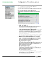
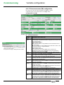
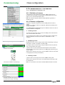
4 T200 settings
This chapter aims to provide the user with all the information needed to be able to
perform configuration of the T200 data.
Certain complex functions of the T200, in particular, require some detailed
explanations (fault detection, automatic control, etc.) for a better understanding of
how to configure the T200.
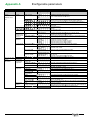
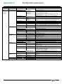
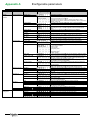
hapter are as follows:
The functions discussed in this chapter
NT00243-EN-03
Comment area
Configuration of SNTP service
Configuration of Ethernet interfaces
Backup/Restoral of configuration parameters
Configuration of communication with the Supervisor
Configuration of switch controls
Configuration of the various options
Automatic control configuration
Configuration of the fault detection module
T200 variable configuration
Class configuration
27
Commissioning
Comment area
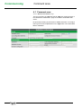
4.1 Comment area :
Access: "Maintenance/Substation" page.
The user can fill in an additional free 50-character
character comments area, in
the "Maintenance/Substation" page of the T200's embedded Web
server.
No special processing is performed on these comments. It is simply a
text to give the user explanations on the equipment or the associated
MV/LV substation.
28
NT00243-EN-03
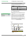
Commissioning
SNTP service setting
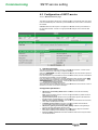
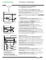
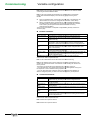
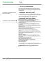
4.2 Configuration of SNTP service
Access: "Maintenance/Clock" page.
The T200 incorporates an SNTP client. It allows the time on the internal clock of the T200
to be set automatically from a network synchronization server, when T200 is connected to
this network.
Comment: When the SNTP option
tion is configured, it overrides manual synchronization of
the T200 time and date. It is then no longer possible to configure the PC time and date
manually.
Operating principle
The T200 includes the capability for defining 2 different SNTP servers, one main server
and one auxiliary server, each being on different networks.
When the "Polling period"" time delay configured has expired, the T200 sends a request to
the main SNTP server.
If the T200 receives a synchronization from the
he main SNTP server, the time on the latter is
set and the synchronization cycle is completed.
If the T200 obtains no response from the main SNTP server after the end of delay "Max.
"
server response time"" has elapsed, the T200 attempts a new connection again.
agai
If the "Number of reconnection attempts"" is reached, the T200 tries to become
synchronized with the auxiliary SNTP server.
The cycle ends once the T200U has been synchronized with the second server or when it
reaches the "Number of reconnection attempts".
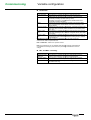
Configuration parameters:
•
•
•
•
•
•
•
NT00243-EN-03
SNTP server and auxiliary SNTP server: IP address of the main and auxiliary
SNTP servers.
Note:: When the address is set to "0.0.0.0", the synchronization by SNTP function is
deactivated on the server.
Synchronization period: Allows the time synchronization period to be defined via
the SNTP server. Configurable from 1 to 300 seconds.
Number of reconnection attempts: Upon failure of synchronization with the server,
max. number of attempts to be made.
Last SNTP synchronization:: Indication of the time and date of the last SNTP
synchronization performed (consultation exclusively).
SNTP server gateway and auxiliary SNTP gateway:
gateway Address of the gateway for
access to the main and auxiliary SNTP servers.
Max. server response time: Maximum time waiting for the reply from the SNTP
server before making a further attempt at synchronization.
Period of validity of the clock: Time after which the T200 must be resynchronized
with the SNTP server.
29
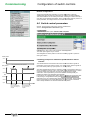
Commissioning
Ethernet interface setting
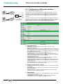
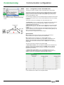
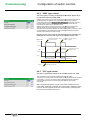
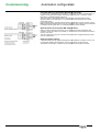
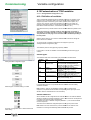
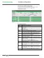
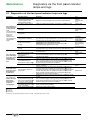
4.3 Configuration of Ethernet interfaces
Access: "Maintenance/IP Parameters" page.
10.x.x.x
ADSL
T200
Supervisor 1
Router
10.a.a.a
10.b.b.b
GPRS
10.y.y.y
Supervisor 2
1 Ethernet interface
2 virtual IP address
This page can be used to configure the Ethernet connection parameters of the T200.
The T200 can include three IP addresses specific to the device, to allow simultaneous
connection from several TCPI/IP network access points including specific address (e.g.
several Supervisors who wants to access
cess T200 from different TCP/IP network – see
example).
The three IP addresses use the same network physical interface (single Ethernet port on
the COM card). For this reason, the two additional IP addresses added to that included as
standard in the "Ethernet Interface" part are called virtual Ethernet interfaces 1 and 2.
Note : The GPRS or 3G port is not is not affected by these virtual addresses.
addresses
•
•
•
•
•
•
•
•
•
•
•
•
30
Interface Ethernet :
MAC address:: Unique identification address for each T200, set in factory.
(Consultation exclusively)
DHCP:: Defines whether the router of the Ethernet local area network can allocate a
new IP address to the T200 automatically upon a new connection. It is recommended
not to activate this function or else you could no longer be able to log on to the T200
if the modified address is not known.
IP address:: Base IP address of the T200 (as standard: 172.16.0.5).
Sub-network mask:: The mask defines the possibility of configuration
configura
of the IP
address on the Ethernet network. For each IP address field, (0) means authorization
of 255 values and (255) means fixed value for this field.
(As standard: 255.255.255.0)
Gateway addresses:: IP address of the server's Ethernet gateway. The gateway
ga
centralizes all the network IP accesses (as standard: 172.16.0.1).
Primary DNS server:: IP address of the primary DNS server (Domain Name Server).
The DNS enables the IP addresses to be associated with the website names (as
standard: 172.16.0.1).
Secondary DNS server:: IP address of the secondary DNS server (Domain Name
Server). Backup DNS server (as standard: 0.0.0.0).
Ethernet virtual interface 1 and 2:
IP address: IP address for the virtual interface. If set to "0.0.0.0", the virtual interface
is deactivated.
Sub-network mask: Sub-network
network mask of the virtual interface (same functioning as
the Ethernet interface).
Gateway addresses: IP address of the Ethernet gateway of the virtual interface
(same functioning as the Ethernet interface).
USB interface:
Server IP address:: IP address of the T200's embedded Web server for USB access.
Unmodifiable (as standard: 212.1.1.10).
Client IP address:: IP address assigned to the PC connected via USB to the
embedded Web server. Unmodifiable. (As standard: 212.1.1.11).
21
NT00243-EN-03
Commissioning
Save/restore configuration
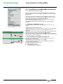
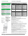
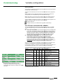
4.4 Save/Restore configuration parameters
Access: "Maintenance/Save-Restore" page.
The T200 can save in file form all the configurable parameters of the equipment
(except the parameters of the "IP parameters"" page which remain specific to each
equipment item).
This file can then be used for downloading to other equipment of the same type,
thus enabling the T200 to be configured automatically without needing to redo the
entire configuration manually, which would be rather onerous.
However, the parameters specific to each T200 must then be personalized (e.g.
(e
protocol address, fault detection thresholds, etc.).
The "Maintenance/Backup-Restoral"" page provides access to backup/restoral
resources.
Saving the configuration on PC:
This section describes saving of the T200 configuration in file form (T200
direction).
PC
There are two possible backup file formats:
- Zipped text file: Click once on the arrow (T200 PC) and the T200 automatically
creates a compressed text file (file with *.zip extension) containing the T200
parameters.
- Binary file: Click once on the "Binary file"" link and the T200 automatically creates
a binary file (file without extension) containing the T200 parameters.
Note: There is in theory no need to use the binary format for backup, except if you
want to generate a backup compatible with
h an old software version of the T200 (see
chapter below: "Backup file compatibility").
Backup/Restore page
NT00243-EN-03
Downloading the configuration from the PC:
This section describes downloading to the T200 the parameters contained in a
backup file (PC -> T200 direction).
In this mode there is only a single button for downloading.
The T200 automatically detects the type of file downloaded and manages the
reading of information accordingly.
It is possible to download three types of files:
Text file (extension: *.txt)
Binary file (without extension)
Compressed text file (*.zip extension).
31
Commissioning
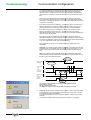
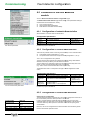
Communication configuration
4.5 Parameters for communication with the
supervisor
The COM card of the T200 is designed to detect automatically the type of modem
that is installed on the communication ports used for transmission to the SCADA
system (ports 1 and 2).
The configuration software automatically proposes a choice of media on these ports
which will correspond to the type of modem installed.
The parameters present in the configuration pages for ports 1 and 2 take into
account
unt the type of medium that has been selected, because each type of medium
has specific configuration parameters.
The configuration page for protocol parameters may take also into account certain
parameters related to the type of medium selected.
Comment: The protocol parameters related to the type of medium will be described
in this chapter. The other parameters related to the protocol will not be described in
detail, however. For more information concerning the latter, refer to the User's
Manual for the protocol.
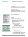
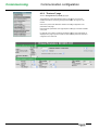
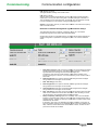
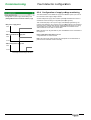
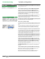
4.5.1 "Operating Mode" page
Access: "Settings/Operating Mode" menu
Objective of this page:: Activate the transmission ports and select the type of modem
to be used and how it will be managed (up to two communication ports available).
The parameters for this page can be consulted and/or modified depending on
the user profile.
Configuration for each port used (Port 1 or Port 2):
Mode: Allows choice (or merely gives an indication depending on the protocol)
of the transmission mode used for dialogue with
th the SCADA system.
Depending on the protocol used, there is a choice between one of the two
modes mentioned below. Some protocols are fixed from the transmission
mode viewpoint and do not allow this choice.
In that case, the T200 proposes merely an indication,
cation, with no possibility of
modification:
- Master/Slave: communicates exclusively in the Scada -> T200 direction.
No remote alarm function used in this mode.
Depending on the protocol, the exact title displayed may be:
"Unbalanced" (e.g. IEC protocol);
"Master/Slave" (e.g. PUR protocol);
"No report by exception" (e.g. Modbus protocol);
"No unsolicited response" (DNP3 protocol).
- Master/Master: communicates in both directions, Scada -> T200 and
T200 -> Scada.
The remote alarm function will be used in this mode if one of the modes
mentioned below corresponding to the Master/Master mode is configured.
On the other hand, the remote alarm function will not be used if the
Master/Slave mode mentioned above is configured.
Excerpted from the page: "Settings/Operating mode"
mode
Depending on the protocol, the exact
act title displayed may be:
"Balanced " (e.g. IEC protocol);
"Master/Master" (e.g. PUR protocol);
"Report by exception" (e.g. Modbus protocol);
"Unsolicited response" (e.g. DNP3 protocol).
Comment: The "Report by exception" mode is not really a Master/Master
Master/M
mode. It is in fact a Master/Slave mode with the possibility of alarm sending
to the SCADA system by means of the "Report by exception" function,
which from the functional viewpoint resembles a Master/Master mode.
32
NT00243-EN-03
Commissioning
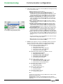
Communication configuration
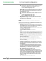
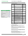
Link: Allows definition of the way in which the ports will be managed according
to one of the following modes:
Off: No transmission over this channel.
Normal:: Main transmission channel to the SCADA system. Two
"Normal" channels with the same protocol but with different
characteristics (e.g. type of transmission) can be used if there are two
remote control systems (main and maintenance). The T200 cannot
manage simultaneous remote controls coming from the two systems.
Balanced – Normal/Standby:: Two channels are necessary in this
mode. The operation of the channels is symmetric. In the event of a
fault on the channel in service, switchover to the other channel takes
place automatically.
Main – Normal/ Standby:: Requires another channel as " Standby –
Normal/Standby". Same operation as "Balanced" but with priority use
of the main channel.
Standby – Normal/ Standby:: Requires another channel as "Main –
Normal/Standby". Same operation as "Balanced" but with use of the
backup channel if failure of the Main channel. A configurable option
can be used to define a priority return to the main channel if the latter
becomes available again.
Store & Forward: Function used only
ly in radio mode. In addition to the
normal channel function of transmission to the SCADA system, this
channel is also used for relaying to an auxiliary T200 located within
reach of transmission and which is not accessible by any other means.
Test: (in radio mode only). Allows a fixed frequency to be generated on
the radio network to allow antenna installation adjustment operations or
level measurements on fields received on another T200 within reach of
the first.
From the page: "Settings/Operating mode"
For further information on the "Normal/Standby" and "Store & Forward"
modes, see the corresponding chapters.
Note: Depending on the protocol, all the operating modes of the ports
mentioned above are not necessarily available.
Medium: Allows definition of the type of transmission medium to be used for
the link to the SCADA system, for each
h port. The choice proposed below
depends on the type of modem detected on the COM card port, namely:
RS232 modem not isolated installed on the port:
♦ Direct RS232 (internal interface)
♦ Radio (external with modem)
♦ PSTN (external modem, Hayes command)
♦ GSM (external modem, Hayes command)
♦ PSTN (UMPC and external modem)
RS232/RS485 modem isolated 2,5 KV installed on the port :
♦ Direct RS232 (internal interface)
♦ Radio (external with modem)
♦ PSTN (external modem, Hayes command)
♦ GSM (external modem, Hayes command)
♦ PSTN (UMPC and external modem)
♦ Direct RS485 (internal interface)
Radio modem installed on the port:
♦ 1200/2400 baud FFSK radio (internal modem)
♦ 600/1200 baud FSK radio (internal modem)
♦ 600/1200 baud LL radio (internal modem)
GSM/GPRS modem installed on the
e port:
♦ GSM (internal modem)
♦ GPRS (internal modem)
GSM/3G modem installed on the port:
♦ GSM (internal modem)
♦ 3G (internal modem)
PSTN modem installed on the port:
♦ PSTN (internal modem)
etc.
Configure the port according to the type of transmission medium wanted
based on the proposed choice.
Important note: A medium not configured or incorrectly configured
generates a fault on the COM card (red fault indicator lamp lit on the front
of the card).
NT00243-EN-03
33
Commissioning
Communication configuration
4.5.1.1
Configuration of Normal/Standby mode
The Normal/Standby mode allows the two communication ports to the Supervisor to
be used in communication redundancy management.
When the "Normal/Standby" mode is configured as link type on ports 1 and 2, the
"Quality of transmission parameters" section becomes
become accessible in the "Operating
modes" page and the corresponding parameters can be configured.
Excerpted from the page: "Configuration/Operating
modes"
This mode requires the use of two communication channels (ports 1 and 2) to
operate.
Two operating modes are possible:
- Balanced mode: No criterion of priority of one channel over the other in this
mode. So long as communication functions on the channel in service, it stays on
that channel. Upon detecting loss of communication on the channel in service, it is
switched over to the other channel. Both channels
nels must be declared as "Balanced".
- Main/Backup mode: In this mode, priority is given to one of the two
communication channels (channel declared as "main"). So long as communication
functions satisfactorily on this channel, it stays on this channel in priority. The
channel declared as "Backup" is used only in the event of operating failure on the
main channel. Return to the main channel can be enabled or inhibited by
configuration ("Authorize return to main channel" parameter). In this case, a time
delayy must be set to define when to perform return to the main channel ("time delay
before return" parameter).
Reception quality criteria:
The T200 uses the transmission quality criteria to define the conditions of channel
changeover.
Two communication criteria quality for the T200 are configurable.
They concern the quality of transmission ("TxQuality") and the quality of reception
("RxQuality"). The value to be entered is indicated as a % of sent and received
frames which are correct.
Two separate cases must be considered:
Master/Master mode (mode with alarms):
When the T200 has to take the initiative of sending frames to transmit an alarm, it
may decide to change transmission channel if the quality of the transmission
connection is not satisfactory. In that case, the T200 evaluates the quality of
transmission according to the quality of the response obtained following a request
upon alarm sent to the Supervisor.
A configurable parameter ("NbSrcv") define the number of repeats to be performed
in the eventt of poor quality of response by the Supervisor after sending an alarm.
The T200 uses this criterion to consider that the connection is poor and that it is
necessary to change over to the other channel.
Master/Slave mode (mode without alarm):
In this mode,, the T200 is Slave. It cannot take the initiative of changing transmission
channel. It must therefore inform the Supervisor that the connection is poor and that
it is necessary to change over to the backup channel.
To do so, the T200 will stop communicating
ng if it considers that the connection is not
good on the channel in service. The supervisor must therefore be capable of
detecting the communication cutoff and take the initiative of changing over to the
other channel.
In this mode, the T200 cannot estimate
te the quality of the connection in
transmission. It is only the reception criteria that are taken into account.
Diagnostic:
For each port, the T200 gives information concerning the number of valid frames
sent and received and a quality percentage relative to the number of frames
handled.
34
NT00243-EN-03
Commissioning
Communication configuration
4.5.1.2
Configuration of Store & Forward mode
The Store & Forward (or repeater) mode is used only in radio communication.
The Store & Forward function allows a T200 to serve as a radio relay for another
distant T200 which cannot be accessed directly by the Supervisor due to access
problems. The Distant T200 must be within transmission range
ra
of the first T200
acting as relay (Repeater T200).
Excerpted from the page: "Configuration/Operating
modes"
Upon detecting a message which is not addressed to it, the Repeater T200 resends
it over the same channel so as to reroute it toward the T200 for which the message
is destined.
Three types of T200 can be managed in the "Store & Forward" mode:
Repeater T200
Distant T200
Supervisor
Obstacle
- Standard T200:: This is a conventional T200. It can communicate directly with the
control centre without going the through Repeater T200. This T200 must be
configured with "Normal" link type.
- Repeater T200: This will act as relay for other T200s which cannot communicate
directly with the Supervisor. This T200 must be configured with "Store & Forward"
link type.
- Distant T200:: This is a distant T200 which cannot communicate directly with the
Supervisor and which
hich will use the Repeater T200 as communication gateway to be
able to communicate with the Supervisor.
This T200 must be configured with "Normal" link type.
Specifications
The Repeater T200 uses the same port (and hence the same radio) to
communicate with the Supervisor and with the Distant T200s.
The Repeater T200 can manage only 10 Distant T200s at most.
These Distant T200s must be declared by configuration in the Repeater T200.
When the "Store & Forward" mode is configured on the Repeater T200, an
a
additional "Store & Forward Parameters" section is displayed in the "Operating
mode" page.
This part can be used to configure for each distant T200:
Scada end link address:: This is the address that will have to be defined at the
Supervisor end to access
ess the Distant T200. This address must be configured
identically in the Repeater T200. This address is used only for the SupervisorSupervisor
Repeater T200 connection.
Distant T200 end link address:: This is the address that will have to be
configured on the Distant
ant T200 and also identically in the Repeater T200. This
address is used only for the Repeater T200-Distant
Distant T200 connection.
The Repeater T200 has its specific link address so that the latter may be used as
a mere Standard T200 in addition to the Repeater function.
NT00243-EN-03
35
Commissioning
Communication configuration
Operation
When the Supervisor wants to communicate
icate with one of the Distant T200s, the
latter sends a protocol frame containing the link address of the Distant T200 to be
accessed.
The Repeater T200 receives this frame and sees that the address was not destined
for it but that it corresponds to the address
ddress of one of the Distant T200s defined in its
list of 10 Distant terminals.
Repeater T200
Supervisor
Address A
Address B
Address A
Address B
Distant T200
The Repeater T200 sends back a frame to the corresponding Distant T200,
replacing the link address with that which has been defined for it in its list for this
Distant T200.
The Distant T200 receives the frame and replies to the request with a frame
containing the link address that is specific to it.
Substitution principe of adresses link :
In blue color : message including address used by the
Supervisor for accessing Distant T200 (e.g. : address A)
In red color : : message including address used by the
Repeater for accessing Distant T200 (e.g. : address A)
The Repeater T200 receives the reply and sends a frame back to the Supervisor
according to the same principle of replacement of the link address between that
used by the Distant T200 and that used by the Supervisor.
Note: When a Master/Master type link is used, the Distant T200 can initiate
communication to send an alarm. The transmission principle remains the same.
Constraints of the Store & Forward function
1°) Due to rerouting of frames from one end or the other of the Repeater, the
transmission times are longer than for direct access on a Normal T200. For this
reason, the reply waiting times will have to be increased on the Distant T200s.
2°) The Repeater function of the T200 uses only a s ingle transmission port. Radio
traffic over this channel is therefore fairly substantial due to the numerous
messages to be re-transmitted
transmitted at the Distant T200 end and the Supervisor end.
Message collisions and repetitions must therefore be expected on the radio traffic.
3°) The handling of messages received by the Repeater T200 is treated as a whole.
The Repeater T200 will end retransmission of the message to be handled to the
Supervisor and the Distant T200 before being able to receive and handle other
messages. This constraint may result in repetition phenomena on devices other
than the Repeater T200.
4°) It should be borne in mind that if a Repeater T 200 can no longer transmit for
whatsoever reason, all the Distant T200s will be affected by this nonnon
communication.
5°) The qu ality of the radio link largely depends on the efficiency of the collision
avoidance function. This function gives good results if the information giving the
busy state of the wireless network is reliable. Now, because the Distant T200s can
pick up frames sent by other T200s, the occupancy state of the wireless network
may be not as efficient as normally. The functioning of the Repeater system may be
degraded for this reason.
36
NT00243-EN-03
Commissioning
Communication configuration
4.5.2 "Protocol" page
Access: "Settings/Protocol (+TCP/IP (1))" page.
ters of this page depend entirely on the type of protocol used.
The parameters
Detailed explanations concerning this page will therefore not be given in this
manual.
Refer to the protocol User Manual for details concerning configuration of the
parameters of this page.
Note that certain parameters of this page depend on the type of modems installed
on the ports.
For example, the "Collision Avoidance Parameters"" section (see image below) is
displayed in this page only when a Radio or PSTN modem (internal or external) is
configured on the COM card.
NT00243-EN-03
37
Commissioning
Communication configuration
4.5.3 "Port 1 (or 2): Transmission" page
Access: "Settings/Port X: Transmission" page
The parameters display for this page depends on the type of modem installed on
the port of the COM card (port 1 or port 2) and on the transmission medium chosen
in the "Settings/Operating Mode" page.
Configuration procedure:
The T200 is factory-delivered
delivered with a default configuration corresponding to the type
of modem installed on the COM card (internal modem) or on the sliding plate of the
enclosure (external modem).
The user should then (if need be) adjust the parameters of this page (in particular
the modem management signals and associated time delays) depending
dependi on what is
required for the modems used or possibly the transmission network.
Concerning the adjustment of transmission delays, in theory one starts by
configuring high values for all the delays, checking first that dialogue is established
between the T200 and the Supervisor.
One starts by gradually reducing the first time delay in order to determine the
operating limit of the modem relative to the adjusted signal.
Then, this delay is increased by several tens of milliseconds to retain a safety
margin.
The procedure is then started again with the other delays.
This method allows T200-Supervisor
Supervisor transmission times to be optimized.
In case of doubt concerning the configuration, it is preferable to leave the default
values.
Modem management signals:
Before
re going into detail concerning the parameters to be configured, the function of
each modem management signal should be explained.
The following timing diagram shows the management signals involved during
communication between the T200 modem and the interface or the external radio, or
even directly with the control centre.
DSR
CD
Received frame
DTR
or
Send Cd
RTS
CTS
Sent frame
Squelch
DSR (Data Send Ready):
This signal can be supplied to the T200 to indicate that the Control Centre (or the
modem) is capable of transmitting (or simply that it is energized).
This signal is used only in the case of an RS232 link (not used in radio mode).
CD (Carrier Detect):
This signal, when it exists, is used to confirm receipt of the received frame. It can
also be used to learn the transmission network
ork occupancy.
DTR (Data Terminal Ready):
When the Control Centre uses DSR, DTR is used to indicate that the T200 is ready
for transmission (equivalent of DSR but in the other direction).
In radio mode with internal modem: This signal is used by the T200 to actuate radio
terminal transition to sending when it requires different commands for transition to
sending and carrier sending.
In radio mode with external modem: This signal is generally not used (with some
exceptions) because RTS is used as the sole command
ommand to cause rising of the send
command and cause rising of the carrier.
38
NT00243-EN-03
Commissioning
Communication configuration
RTS (Request To Send):
This signal actuates sending of the modem carrier
CTS (Clear To Send):
quest To Send, the sender sometimes takes a
After the T200 has performed the Request
certain time to rise in power before being able to send the messages submitted to it.
This is especially true for radio equipment. Accordingly, when the equipment is ready
to send, it indicates this to the T200 byy causing the CTS signal to rise.
Squelch: This signal is used only in radio mode to indicate to the T200 the occupancy
state of the radio network.
Definition of modem management signals and time delays:
The T200 allows the user to configure, if necessary, use or not of the modem
management signals and the various associated time delays.
We give below the list of configurable options concerning these modem management
signals. Configuration is performed in the pages for ports 1 and 2 of the T200 Web
W
server:
NT00243-EN-03
•
Delay before response:: After receiving a message, this is the waiting time before
sending the message (response). This delay serves to avoid any overlapping of
signals between the message received and the message sent.
This delay is often used with a radio medium or with certain modems which
require a time lag to turn around, i.e. a minimum time to go from receive mode to
send mode.
♦
DTR management: If this option is selected, the DTR signal will be managed
during transmission exchanges with the modem.
•
DTR - RTS delay (if RTS used):
♦
RTS management: If this option is selected, the RTS signal will be managed
during transmission exchanges with the modem.
♦
CTS management If this option is selected, the CTS signal will be managed
during transmission exchanges with the modem.
♦
RTS - CTS delay (if CTS used): This is the maximum time during which the T200
waits for the CTS after the RTS has been activated. If, after this delay,
delay CTS has
not become active, the T200 discontinues sending the frame.
•
RTS (or CTS) delay - Message (if RTS or CTS used): This is the time between
transition to the active state of RTS (or CTS if this signal is used) and the start of
message sending. Typically
lly this time lag is used to wait for a stable carrier period
established by the modem.
If necessary, when CTS is not available, the time for installation of the carrier to
solve the problem posed by the non-availability
availability of this signal can be added to this
delay. Likewise, if the DTR and RTS commands are common, the time for rise in
power of the sender can be added.
39
Commissioning
Communication configuration
Note: Example of delay to be configured on the T200, depending on the type of
radio:
Message delay = 150 ms
- Motorola CM 340 or GM340 radio: RTS-Message
- TAIT 811x radio: RTS-Message
Message delay = 100 ms
- MDS4710 radio: RTS-Message
Message delay = 50 ms
♦
Message - RTS delay (if RTS used):: This is the minimum time to be waited, after
sending a message, before causing RTS and DTR (or Send command) to fall
again. This delay prevents the end of the message from being truncated by the
premature fall of modem sending.
Note: Example of delay to be configured on the T200, depending on the type of
radio:
- Motorola CM 340 or GM340 radio: Message - RTS delay = 100 ms
- TAIT 811x radio: Message - RTS delay = 80 ms
- MDS4710 radio: Message - RTS delay = 50 ms
♦
DSR management If this option is selected, the DSR signal will be managed
during transmission exchanges with the modem.
♦
CD management: If this option is selected,
cted, the CD signal will be managed during
transmission exchanges with the modem.
General parameters (common to the various transmission
media):
As a general rule, certain configurable parameters of the ports 1 and 2 pages are
common to numerous types of modems. We shall describe in detail here the meaning
of these parameters and how to configure them.
40
♦
Baud rate:: This is the speed of transmission between the T200 and the modem.
When an external modem is used, the configured speed is not necessarily the
speed
ed that will be used for the link to the Supervisor, because the external modem
can use a different speed to that used for the RS232-T200
RS232
link.
The choice of available speeds differs depending on the type of modem installed
on the ports. Here are a few examples:
FFSK radio: 1200 or 2400 baud
External radio or internal RS232: 200 to 38400 baud
Internal GSM: 600 to 9600 baud
etc.
♦
Parity: This is the frame character parity for transmission to the Supervisor. Some
modems do not manage parity. In such cases, the T200 will have to be configured
with the "No parity" option. To be defined therefore according to the type of
modem used. Of course, the Control Centre must also be able to be configured in
this mode.
Note that when the parity is no longer used, transmission
transmiss
security is diminished
and a disturbed frame may be considered correct. (See protocol manual for more
details concerning this function).
There are four possible configurations: no parity, space, even or odd.
Note: Parity is not used in PSTN, GSM, GPRS, 3G and FFSK radio links.
♦
Number of stop bits: This is the number of stop bits used to define the end of a
frame during transmission.
There are two possible configurations: one or two stop bits.
•
Frame error on idle line: The T200 is capable of detecting a gap greater than 1
bit between 2 characters of a frame.
With certain protocols, any frame having this feature can be rejected. This allows
secure transmission.
This frame rejection will be activated if this option is set to "Yes".
This configuration implies
ies that the Supervisor and the modems involved in the
transmission circuit ensure that there are no gaps. While this is sometimes true
with regard to the Supervisor, it is not completely true for many modems (case of
packet transmission). In this specific case, "No" should be set. However,
transmission security must then be ensured by other means (see User Manual of
the protocol used for more information).
Note: This parameter is used only on a radio or LL link.
•
Frame error on noisy outgoing cable: Some transmission networks could
constantly generate noise just at the start of frame. In that case this option should
be set to "No", to avoid systematically rejecting all the received frames which
could be considered incorrect. However, the incorrect character
characte generated by the
noise located in the frame header will be eliminated when reading the frame,
because this character will not correspond to what is expected by the protocol.
Note that, in most cases, this noise does not exist. In such cases, the option
should be set to "Yes".
Note: This parameter is used only on a radio or LL link.
NT00243-EN-03
Commissioning
Communication configuration
Parameters specific to each transmission medium:
In this chapter we shall describe in detail the configuration parameters specific to each
modem (the other parameters having
ng been described in detail in the preceding
chapter):
PSTN and GSM medium (internal or external modem):
♦
Dialing type: Choice of the type of dialling to be used for the telephone call
to the Supervisor during an alarm sequence.
There are two possible choices: pulse (decimal) and multifrequency (MF).
Note: Configuration available in PSTN but not in GSM.
♦
Modem Init: The Modem Init sequence is necessary to configure the modem
for operation linked to the T200 application.
The defaultt Init sequence corresponds to the AT commands necessary for
an internal modem (modem installed on the COM card). For an external
modem, the Modem Init sequence is not defined in the configuration
supplied. It is up to the user to define it according to the
th brand and model
used (refer to the modem manual).
Note: Configuration available in PSTN but not in GSM.
NB: The Modem Init sequence is sent to the modem only after initialization of
the T200 COM card (following a reset or power up of the T200). After
changing
anging the Init sequence, you must remember to reinitialize the COM card
for it to be taken into account by the modem.
Default Init sequence: &F0%S0=12S0=1&K0%C0E0&W0&Y0.
&F0%S0=12S0=1&K0%C0E0&W0&Y0
If in doubt, do not change this default Init sequence, because the T200T200
Supervisor link is likely to no longer operate correctly.
♦
Caller communication delay: Maximum delay for connection between the
T200 and the Supervisor following a call by the T200 before release of the
PSTN line by the T200.
♦
Called communication delay: Maximum delay
dela for connection between the
T200 and the Supervisor following a call by the Supervisor before release of
the PSTN line by the T200.
♦
Host tel number (main): Main phone number that the T200 uses to call the
Supervisor during an alarm sequence.
The T200 will try to call three times on this "normal" number before switching
to the "Backup" number.
♦
The codes accepted for telephone numbers are:
0 to 9 (for the call number);
P (for Pulse = decimal dialling setting);
T (for Tone = MF dialling setting);
W (for Wait);
space bar (for space);
+ (equivalent to "00" for international dialling).
Example of config.: "P 00W0674948960" or "P +W0674948960"
Note: A space must be inserted between the "T" or "P" and the call number.
♦
NT00243-EN-03
Host telephone number (Standby): Secondary phone number that the
T200 uses to call the Supervisor during an alarm sequence. This phone
number is used only if the main number does not reply (i.e. after three
unsuccessful attempts).
The T200 will also try to call three times on this second number before finally
stopping calling, unless another alarm occurs, which will have the
consequence of reinitiating the alarm calls from the "Normal" number).
Same comment as for the "Normal" number concerning the codes to be used
for the call number.
41
Commissioning
Communication configuration
GSM medium (internal or external modem):
08:48:34.474
08:48:35.986
08:48:36.994
08:48:39.518
08:48:42.045
08:48:43.071
08:48:44.079
08:48:45.120
08:48:45.120
08:48:47.230
08:48:47.230
08:48:49.770
08:48:50.807
08:48:50.807
08:48:54.818
08:48:57.347
08:48:59.875
08:49:02.403
08:49:04.929
08:49:07.455
08:49:09.983
08:49:12.509
08:49:15.039
08:49:17.567
08:49:20.101
08:49:20.101
MODEM - Power up
MODEM - Command mode
MODEM - Tx : ATE0
MODEM - Tx : AT&S0
MODEM - Tx : AT
MODEM - Rx : OK
MODEM - Tx : AT+CPIN?
MODEM - Rx : +CPIN: SIM PIN
MODEM - Tx : AT+CPIN=****
MODEM - Rx : OK
MODEM - Tx : AT+CLCK="SC",0,****
MODEM - Tx : AT+CREG?
MODEM - Rx : +CREG: 0,1
MODEM - Tx : AT+CSCA=0689004000
MODEM - Tx : AT+CMCF=1
MODEM - Tx : AT+CSAS
MODEM - Tx : AT+CMEE=0
MODEM - Tx : AT&C1
MODEM - Tx : AT&D2
MODEM - Tx : AT+IPR=0
MODEM - Tx : ATS0=1
MODEM - Tx : AT+WIND=0
MODEM - Tx : AT+CICB=0
MODEM - Tx : AT+CBST=7,0,1
MODEM - Tx : AT&W
MODEM - Modem GSM initialized
Example of port trace during an attempt to connect
to the GSM network (Modem Init)
11:38:37.093 SlaveAddr = 03
<<<<<
11:38:37.113 SlaveAddr = 03
>>>>>
11:38:37.357 SlaveAddr = 04
<<<<<
11:38:37.593 SlaveAddr = 04
<<<<<
Reading N output words
Addr = 0x34
03 03 00 34 00 03 45 E7
Reading N output words
03 03 06 A9 AA AA A9 55 00
F6 9C
Reading N output words
Addr = 0x0
04 03 00 00 00 01 84 5F
Reading N output words
Addr = 0xf
04 03 00 0F 00 21 B5 84
Example of exchange frames during connection
established with the Supervisor (in Modbus
protocol)
Yellow status
indicator of
connection to the
GSM network
♦
PIN Number: Configuration of the SIM card PIN code on four figures.
NB: After three validations of the page configuration or three modem
initializations with an incorrect PIN code, the SIM card is blocked. The only
solution in this case is to call the operator who will
w be able to unblock it.
The first time that the T200 initializes the GSM modem, the latter asks the
modem if it needs the PIN code.
If the modem replies in the negative, the T200 will not manage the PIN code
and the latter will not need to be entered byy the user.
On the other hand, if the modem replies that it needs the PIN code, the T200
will manage this parameter and the PIN code must therefore be configured.
Once the PIN code has been initialized a first time, the T200 asks the
modem to deactivate use of the PIN code.
The latter will therefore no longer be used by either the T200 or the GSM
modem.
♦
SMS service centre tel number: This is the number of the service centre of
the GSM operator which centralizes and stores all the SMS messages sent
to reroute them to the end user.
Contact the operator to know this number. It is also possible to find out this
number from a GSM telephone using the same operator as that used by the
SIM card of the T200, because the number can be looked up in the
telephone's configuration parameters.
Finally, it is also possible to find out this number in the port trace following
connection of the modem to the GSM network. The number is displayed on
the line including the "AT+CSCA" command (see enclosed example:
number=0689004000).
♦
SMS user tel number: SMS number that the T200 uses in the event of an
alarm sequence to send the text message to the user who is
i on standby
duty.
Same comment as for the "Normal" telephone number concerning the codes
to be used for the telephone number.
GSM modem connection status:
To check the connection status of the GSM modem, there are several
possibilities:
By flashing of the
e indicator lamp on the front of the GSM modem:
- The indicator lamp is lit steadily:: the modem is not connected to the
GSM network.
- The indicator lamp flashes slowly (every 2.5 seconds): the modem
is connected to the network but there is no remote link.
- The indicator lamp flashes rapidly (every second): the modem is
connected to the network and a remote link is established.
By consulting the AT commands for modem initialization in the port
trace corresponding to the GSM modem: To the "AT+CREG"
"
command
requested by the T200, the modem should reply "+CREG:
"
0.1" when
the modem is connected to the network or "+CREG:
"
0.2" if it is not (see
example opposite).
Moreover, when the remote link is established between the T200 and
the Supervisor, the port trace also
lso displays protocol frame exchanges
between the T200 and the Supervisor.
Indications on the front panel of the GSM modem
for the COM card
42
NT00243-EN-03
Commissioning
15:59:28.157
15:59:30.683
15:59:33.210
15:59:35.741
15:59:48.333
16:00:18.546
16:00:19.581
16:00:19.590
16:00:39.732
16:00:40.766
16:00:40.774
16:01:00.916
16:01:01.950
16:01:01.957
Communication configuration
MODEM - Tx : AT+WIND=0
MODEM - Tx : AT+CICB=0
MODEM - Tx : AT+CBST=7,0,1
MODEM - Tx : AT&W
MODEM - Modem GSM initialised
MODEM - Asking for level reception
MODEM - Rx : 20
MODEM - Rx : OK
MODEM - Asking for level reception
MODEM - Rx : 20
MODEM - Rx : OK
MODEM - Asking for level reception
MODEM - Rx : 23
MODEM - Rx : OK
Level of GSM reception :
It is possible to know the level of GSM signal received by the modem of
T200.
This function is very useful to know if the T200 can correctly received frames
f
from the Supervisor or to adjust the installation of the antenna on the support
to optimize the reception.
To know the level of GSM signal received, you just have to consult the port
trace corresponding to GSM modem.
Once the modem is initialized, the
he T200 display automatically on screen the
level of GSM signal reception.
Remark : When the T200 detect a frame form the Supervisor, the display of
protocol frames gets priority from the GSM level indication.
Possible values for GSM signal :
The SMS messages sent contain the following information:
• Identification of the substation:
- equipment type (F200)
- slave address in Modbus, link address in IEC, etc.
- name of substation (configurable)
• Identification of the variable:
- variable name (configurable)
- variable state (configurable text associated with state 0 or
1 for digital, value + unity for analogue)
- change of state time
- Reception GSM not detectable : level = 99
- Reception GSM not sufficient : level = 0 à 10
- Reception GSM correctly detected : level = 11 à 31
• Example of SMS message:
F200 125, Salvagny substation. Digital input 1: Deactivated
25/10 17:35:45
FSK or FFSK radio medium (internal or external modem):
♦
Caller communication delay: Maximum delay for connection between the
T200 and the Supervisor following a call by the T200 before release of the
radio link by the T200.
♦
Called communication delay: Maximum delay for connection between the
T200 and the Supervisor following a call by the
t Supervisor before release of
the radio link by the T200.
FSK LL 600/1200 baud medium (internal modem):
♦
NT00243-EN-03
Line type: Configuration of the type of LL line installed between the T200
and the Supervisor.
There are two possible configurations: two--wire or four-wire.
43
Commissioning
Communication configuration
RS485 medium (internal modem):
♦
Polarization: Activates line polarization at the T200 end. The RS485 line
should be polarized at one termination, generally at the Master end.
♦
End-of-line resistance: Activates the load résistance at the T200 end. The
RS485 line should be loaded at both its terminations.
♦
Line type: Choice of type of transmission used: 2-wire
2
or 4-wire.
GPRS or 3G medium (internal modem):
GPRS/3G operating conditions on T200:
For GPRS or 3G communication between the T200 and the Supervisor to be able
to operate, certain essential conditions must be obtained from the network
operator:
- The T200 must have a fixed IP address assigned by the operator:
The GPRS or 3G connection will not be able to operate if the T200 has a dynamic
IP address, because at the Supervisor end it will not be possible to know the new
IP addresses assigned to the T200 by the operator following a reassignment. As a
result,
ult, it will not be possible to initialize protocol communication from the
Supervisor.
Likewise, it will not be possible either to log on to the embedded Web server of
the T200 remotely from an Ethernet access if the IP address of the T200 is not
known.
The
he only way to know the IP address of the T200 in this case is to log on locally
(on site) to the embedded Web server of the T200 via an USB access, which is
hardly possible because that would imply going to the site for each enclosure
each time an IP address is reassigned.
As soon as the T200 is connected to the GPRS or 3G network, the IP address
assigned to the T200 is displayed in the "Server
Server IP address" field that can be
consulted in the "Maintenance/IP server ports"" page (see image below). It is this
address that must be used at the Supervisor end to connect to the T200 via
Ethernet or via the protocol.
Comment: When connection to the GPRS or 3G network is not established,
dashes ("-")
") are displayed in place of the IP addresses.
-
The IP ports used
d by the T200 must be opened by the operator:
A number of ports are used for the T200 application. The list of ports
used can be consulted in the "Maintenance
Maintenance - IP server ports" page of the
T200 Web server (see image below). All the ports mentioned in this page
must be opened at the GPRS/3G operator level for the functions
associated with these ports to be able to operate. If this is not the case, it
is always possible to select different port numbers in this page to match
port numbers available at the operator
ator end.
Example: "HTTP server" port N°80 is not open for the operato r
"Orange". A port number greater than 1024 should be configured on the
T200 to have an open port from this operator.
44
NT00243-EN-03
Commissioning
Communication configuration
Configuration of GPRS or 3G parameters:
♦
Access Point Name (APN): Access Point Name. Name of the access point for
connection to the GPRS/3G network. This name is generally given by the operator
who provides access to the GPRS/3G network.
(e.g. "internet-entreprise"
entreprise" for the operator Orange).
♦
PIN number: Same as for GSM modem.
♦
Daily disconnect: One of the special features of GPRS/3G operation is that in
some cases of network unavailability, the T200 does not detect this link break.
The T200 will therefore remain connected continually to the network
netwo (unavailable)
even though the physical link is broken. The T200 can therefore remain
indefinitely in this mode and will no longer have a means of reconnecting to the
network, even if is available again, because to do so it would have to be forced to
disconnect
connect from the network to then be able to reconnect.
As a consequence, without a means of forcing automatic
disconnection/reconnection, the T200 will not by itself be able to restore
connection to the network.
ore been provided to play this role and
The "Daily disconnection" option has therefore
thus allow T200 disconnection from the GPRS/3G network to be forced
automatically so as to reconnect it immediately afterward. This disconnection can
be programmed for a fixed time each day by means of the "Disconnection
"
time"
setting.
This system works, but has the disadvantage that in the worst case scenario the
T200 may remain for at most 24 hours without any real connection to the network
(case of a brief network failure occurring just after the daily disconnection
di
time).
♦
Disconnect hour: Configuration of the selected daily disconnection time
according to the criteria described previously in "Daily
"
disconnection".
This option should be entered only if the "Daily
Daily disconnection"
disconnection option is used.
♦
PPP session timeout: Configuration of the delay maximum before disconnection
of T200 from GPRS/3G network, in case of no data transfer detected by the T200.
♦
Specific ping IP address: The ping in theory makes it possible to verify and
measure the quality of the equipment's
pment's connection with another device connected
to the IP network.
This configurable parameter can determine to what IP address will be sent the
packet corresponding to the ping allowing this quality to be measured.
Configure, for example, a known Web server
ver IP address or possibly that of the
supervisor, provided that the latter incorporate a known fixed IP address.
The configured address must correspond to a standard IP address format, i.e. be
in the form of four values of at most three digits separated by
b a dot (e.g.
192.168.2.101).
Operating principle of the regular ping test:
For the T200 application, the regular ping test is used chiefly as a means of
extending connection to the GPRS/3G network, when the Supervisor is no longer
capable of performing protocol communication with the T200 even though the
GPRS/3G network is still operational. Now, the T200 is designed to monitor the IP
data packet flow reaching it via the GPRS/3G network.
A 5 min. time delay (“PPP session timeout”)
”) automatically disconnects the T200
from the GPRS/3G network if no IP data flow reaches the T200. Accordingly, if the
T200 is disconnected from the network, the modem will be reinitialized, thereby
making the T200 unavailable
navailable for 1 min., the time needed for reconnection of the
modem to the GPRS/3G network.
NT00243-EN-03
45
Commissioning
Communication configuration
To avoid this drawback, the regular ping test is used to prevent disconnection of
the T200 when the problem is exclusively due to the Supervisor and not to a
network problem. In other words, if the T200 is still connected to the GPRS/3G
network, there is no
o reason to disconnect it because of a non-existent
non
IP protocol
flow.
As soon as a ping address has been configured in this field, the T200 will try
every 4 minutes (“Ping time interval”)
”) to send a ping to the specified IP address.
Accordingly, an IP data flow will return to the T200 and the latter will not cut off the
connection to the network.
If the result of the ping test is satisfactory, the T200 will remain connected to the
network, because it knows that it is available. The T200 will then do nothing
nothin in
particular except for the next ping test following the next 4 minutes elapsed.
If the result of the ping test is unsatisfactory, after an extra minute the T200,
seeing no IP data flow for the last 5 min., will disconnect from the network
automaticallyy (modem reset), and then try (after the end of modem initialization) to
reconnect to the network again.
If the network is still not available, the T200 will again request the modem to
reinitialize immediately, and this indefinitely until the next detection
detecti of the network.
This phase of initialization and reconnection to the network requires approximately
1 min. for the GPRS/3G modem (see enclosed diagram).
If the ping address is set to "0.0.0.0" (default value), the regular ping test is
deactivated.
Comment: The regular ping test method is preferable to the "Daily disconnection"
method because, for the regular ping test, network disconnection lasts only 5 min.
at most during a brief failure (case of network disconnection just after the ping
test).
Note: The regular (or manual) ping test sends to the specified IP address the
smallest possible number of data packets (equivalent to 0 byte), to avoid causing
the extra cost of an IP data flow transfer.
Problem on
GPRS network
Yes
GPRS network
availability
No
T200 power up
1
GPRS modem
reset
T200
connection to
the GPRS
0
Yes
Supervisor
protocol
frames
TC
Test
ok
No
1
Automatic ping
test
TA
TB
TA
TA
TA
Test
failed
Test
ok
TB
TB
0
T200 stays
connected
Supervisor
inoperative
TA = Time for modem initialization + connection to the GPRS/3G network
(approximately 1 minute)
TB = Ping test period (4 minutes)
TC = Modem reset time (= 5 min.) if IP data flow non-existent
non
on the T200
♦
46
Test Ping: Allows manually activation of the ping test. A click on this button starts
a manual ping test. This manual test is generally used to verify T200 connection
to the GPRS/3G network immediately.
The T200 then displays the result of the test in a specific window (see enclosed
windows).
There are two possible results following this test: "Ping
"
Ok" or "Ping failed"
NT00243-EN-03
Commissioning
08:48:34.474 MODEM - Power up
08:48:35.986 MODEM - Command mode
08:48:36.994 MODEM - Tx : ATE0
08:48:39.518 MODEM - Tx : AT&S0
08:48:42.045 MODEM - Tx : AT
08:48:43.071 MODEM - Rx : OK
08:48:44.079 MODEM - Tx : AT+CPIN?
08:48:45.120 MODEM - Rx : +CPIN: SIM PIN
08:48:45.120 MODEM - Tx : AT+CPIN=****
08:48:47.230 MODEM - Rx : OK
08:48:47.230 MODEM - Tx : AT+CLCK="SC",0,****
08:48:49.770 MODEM - Tx : AT+CREG?
08:48:50.807 MODEM - Rx : +CREG: 0,1
08:48:50.807 MODEM - Tx : AT+CSCA=0689004000
08:48:54.818 MODEM - Tx : AT+CMCF=1
08:48:57.347 MODEM - Tx : AT+CSAS
08:48:59.875 MODEM - Tx : AT+CMEE=0
08:49:02.403 MODEM - Tx : AT&C1
08:49:04.929 MODEM - Tx : AT&D2
08:49:07.455 MODEM - Tx : AT+IPR=0
08:49:09.983 MODEM - Tx : ATS0=1
08:49:12.509 MODEM - Tx : AT+WIND=0
08:49:15.039 MODEM - Tx : AT+CICB=0
08:49:17.567 MODEM - Tx : AT+CBST=7,0,1
08:49:20.101 MODEM - Tx : AT&W
08:49:32.706 MODEM - Tx : AT+CGCLASS?
08:49:33.720 MODEM - Rx : +CGCLASS: "B"
08:49:33.720 MODEM - Tx : AT+CGDCONT=1,"IP","internetAT+CGDCONT=1,"IP","internet
company"
08:49:36.248 MODEM - Tx : AT+CGATT=1
08:49:38.769 MODEM - Tx : AT+CGREG?
08:49:39.784 MODEM - Rx : +CGREG: 0,1
08:49:39.784 MODEM - Tx : AT+CGACT=1,1
08:49:42.307 MODEM - Tx : ATD*99***1#
08:49:43.327 MODEM - Connection
08:49:44.335 MODEM - PPP link: UP ->
> ESTABLISH ()
08:49:44.350 MODEM - PPP link: OPEN -> AUTH ()
08:49:44.363 MODEM - PPP link: PAP: Local successfully
authenticated
08:49:44.363 MODEM - PPP link: SUCCESS ->
> NETWORK ()
08:49:44.363 MODEM - PPP link: IPCP UP ->
> NETWORK ()
08:49:44.400 MODEM - PPP link: IPCP CONFIGURED ->
NETWORK ()
08:49:44.401 MODEM - PPP link: connected,
local=90.95.65.78, dest=212.234.96.90
08:49:44.401 MODEM - GPRS modem initialized
Example of port trace in the event of a connection
to the GPRS network
Communication configuration
♦
Ping time interval: Delay between two successive automatic “Test ping”.
♦
Ping attempts: Number of maximum attempts for the “Test ping” process in
case of no response from remote IP address.
♦
Ping time out: Maximum delay to wait for the response during the “Test
ping” to define “Ping error”.
♦
Authentication: When the GPRS/3G network requires authentication during
the connection phase, it is possible in such cases to activate this function by
checking the corresponding box.
The authorized encryption protocols are:
- PAP, CHAP, MSCHAP, MSCHAP V2
♦
Login: Configuration of the
e login used for authentication. Configure this field
only if the "Authentication"" option has been checked.
♦
Password: Configuration of the password used for authentication. Configure
this field only if the "Authentication"" option has been checked.
Note: To check that the modem is correctly connected to the GPRS/3G
network, it is possible to consult the trace of the port corresponding to the
GPRS/3G modem. The modem starts by initializing the GSM connection and
then the GPRS/3G connection. Accordingly, following
fol
the AT commands for
connection to the GSM network can be found the commands relating to
GPRS/3G connection. At the end of them, the trace should indicate
"GPRS/3G modem initialized" with also the indication of the IP addresses of
the T200 assigned by the operator (local=xxx.xxx.xxx.xxx) and the IP address
of the GPRS/3G gateway provider (dest=xxx.xxx.xxx.xxx) (see example
opposite).
Modem connection status:
Same comment as for the GSM modem.
Connection speeds in TCP/IP communication
Depending on the connection type, the T200/Scada link can be implemented at
different speeds. This is a maximum connection speed. They depend on many
factors such as the network's availability, the received signal level or the location
of the receiver:
•
•
•
GPRS:
PRS: max. bit rate = 19.2 Kbits/s (in practice)
EDGE: max. bit rate = 64 Kbits/s (in theory)
3G: max. bit rate = 2 Mbits/s (in theory), 115 Kbits/s (in practice)
Automatic switchover of the 3G modem
The 3G modem has the feature that it can automatically switch over to EDGE or
GPRS mode if the 3G connection is momentarily unavailable, with the possibility
of returning to 3G mode automatically if connection is restored. This provides a
backup for the TCP/IP link.
Connection is therefore preserved in the event
ent of a network problem, on condition
that the other EDGE or GRPS modes are available. Only the transmission rate is
affected by this automatic switchover from one network to another.
NT00243-EN-03
47
Commissioning
Configuration of switch controls
Remote configuration:
The @ sign alongside each parameter of "Control &automation"
&automation page and
"Measurement and fault indicator" page allows to configure an external address.
This external address can be used by the SCADA, to configure or define remotely a
new value for the parameter associated, via the communication and the protocol. To
set the parameter, an analogue value can be written to this
th address.
4.6 Switch control parameters
Objectif : Set processing of the switch control for each channel.
Access: "Settings/Control & Automation" page.
► Type of control:
There are four possible options: Standard, PM6, CI2, Other
application
Comment: The "CI2" choice must be used for T200S application.
The "PM6" option applies only for T200 P.
The management of switch position control and monitoring signals is specific to
each type of switch.
Closed position
Active
Filtering
principle for indication inputs related to remote
controls:
Inactive
Non-complementary switch positions
Open position
Active
The interface between the T200 and the switch includes two electric signals for
motorization control (CO: Opening control / CF: closing control) and two signals for
the current switch position (O: open position / F: closed position).
The T200 systematically performs a consistency check on the positions read: it is in
theory impossible to have the "open" and "closed" signals simultaneously or neither
of the two signals at the same time, but this may occur following a system
malfunction. This
is complementary of the switch states is verified cyclically for
updating the states of the associated TSD variables.
In the case of non-complementary
complementary values, filtering is applied and the old TSD value
is kept during a configurable time delay (see No complementary
compl
filtered time
parameter). If the non-complementary
complementary persists after the time delay, this is probably
due to a fault relating to the signals delivered by the switch and the "undefined"
state is finally indicated in the TSD associated with the position.
Inactive
TSD
Undefined
Closed
Open
Non-complementarity
filtering time delay not
elapsed
48
Non-complementarity
filtering time delay
elapsed
NT00243-EN-03
Commissioning
Configuration of switch controls
Principle
for switch position order processing:
The T200 internal control manager inhibits any order until the previous order has
been completed. The order processing status can be known by consulting the
events from the supervisor or in the local event log.
The events generated according to the order processing status are summarized in
the following table:
Phase
Event
Receipt of a switch order
TCD xx - Switch state - Order
CR order in progress
End of order processing
CR end of order
End of degraded order
processing
CR external error or CR severe fault
CR end of order
4.6.1 "Standard" type control
Reminder: The "Standard" configuration applies to the main switches used with the
T200 I application such as SM6 or RM6. Not applicable for T200S on which "CI2"
configuration is required.
The principle of an order on the switch is to activate the
th switch control signal (24V
or 48V polarity depending on the model) for a determined time (Operating
(
time
parameter).
With "Standard" control, the duration of the order is therefore fixed by this time
delay and does not depend on the time taken by the switch to change position.
The Open and Closed switch position inputs are read constantly throughout the
duration of the order with a consistency check so as to update the associated
position TSD variable (see Filtering principle for indication inputs related to remote
controls).
After the control relay has fallen, the order is considered as completed by the T200
when the switch indicates a position in conformity with the order (the TSD is
updated with the new status). The order is considered in error (e.g. external error) if
the position is not in conformity with the requested order or if undefined after a loss
of position filtering time delay (Return
Return position waiting time).
Closing control
Active
Inactive
Opening control
TCD Switch state Order sending
CR: order in progress
TCD Switch state Order sending
CR: order in progress
Active
Inactive
CR: external error
CR: end of order
TSD
TSD Switch position - Open
CR: end of order
Closed
Open
Return position waiting time
Control unsuccessful
Legend :
NT00243-EN-03
T < Return position waiting time
Control successful
Event recorded in event log
49
Commissioning
Configuration of switch controls
4.6.2 "PM6" type control
This switch option is in theory not applicable for the T200 S. Applies only to
the T200 P associated with a PM6 switch.
With this type of switch, the principle is to apply the motor control signal until the
requested position is obtained. This control will be maintained only during a
configurable limited period (Return
Return position waiting time parameter), and this in
the event that the position indicated by the TSD variable is not that which is
expected by the T200 (case of degraded control).
With this type of switch, the time for execution of the electrical order therefore
depends exclusively on the time taken by the switch to change position.
The Open and Closed switch statuses are read constantly with a consistency check
chec
so as to update the associated position TSD variable (see Filtering principle for
indication inputs related to remote controls).
Important remark : In this mode, the open and close control command to the
switchgear are send to the same signal, ie open command signal ("OC").
CO/CF control
TCD Switch state Order sending
CR: order in progress
TCD Switch state Order sending
CR: order in progress
Active
Inactive
CR: external error
CR: end of order
TSD
TSD Switch state - Open
CR: end of order
Closed
Open
Return position waiting time
Control unsuccessful
Legend:
T < Return position waiting time
Control successful
Event stored in event log
4.6.3 "CI2" type control
This option is applicable for T200S. Can be eventually used also for T200I.
T200I
The management of control signals is identical to the mode "PM6".
The choice "CI2" relates to the type CI2 of SM6 cubicle that permits a fast operation
of the switch (< 100 ms). The
he need for rapid operation is generally required for
source transfer applications, to minimize the interruption of power supply
downstream.
Note : the signal management control of the switch is different from the
mode "PM6". Unlike the mode PM6, the control signal to initiate the switch
is sent on the wire opening control "OC" and the closing control signal is
sent over the wire closure control "CC".
50
NT00243-EN-03
Commissioning
Configuration of the various options
4.7 Parameters of the various options
Access: "Settings/Control & automation" page.
Some specific options allow operation of the T200 to be customized for the needs of certain
users.
One must be a system administrator to be able to modify these options.
The T200 is generally delivered without these specific options being activated (factory
settings).
The list of these configurable options is described in detail below:
DDEF test (DOUT 2):
When this option is selected, digital output DOUT 2 is activated whenever a current
exceeds the phase or earth fault detection threshold configured on the T200.
The output goes low as soon as the fault returns below the threshold.
8 bits measurements
s as in T200 series
ser
2:
By default, on the T200 S series 3, the current (or voltage) measurements are coded on
16 bits, whereas on the preceding series they were coded on 8 bits. By selecting this
option, however, it is possible to make the T200 compatible with the old-generation
old
T200s. This option is used especially when a Supervisor already polls T200s of an old
generation with measurements on 8 bits. Now, a given Supervisor can hardly read
measurements in 2 different formats.
Note: Same comment as for the previous option concerning the possibility of using the
"OFF Line Configurator" to generate a configuration file compatible with this option.
Manual control allowed when ATS is in operation
In theory, when automatic control is active, manual controls on the channels
chann
are not
authorized, because it is the automatic control system that has control.
However, by activating this option, manual controls on the channels are authorized
when the automatic control system is operational. Valid on local controls (via the local
panel or via the configuration PC) and remote controls (via the Supervisor).
Note: recommended position = not checked
ATS locking in case of fault detection
When this option is activated, the automatic control system is locked automatically upon
detecting
ng the presence of fault current on one of the two channels managed by the
system. Otherwise, the automatic control system does not take into account fault
detection on these channels in order to operate.
Note: recommended position = checked
Parallel mode
e allowed in automatic mode
Activating this option enables paralleling of the channels by automatic control, during
the phase of automatic return to the priority channel.
NB: The dedicated digital input (DI 5) must also be activated to authorize paralleling.
parallelin
Note: recommended position = not checked
Parallel mode allowed by manual control
Activating this option enables paralleling of the channels manually (via the local panel or
via the configuration PC) or remotely (via the Supervisor).
NB: The dedicated digital input (DI 5) must also be activated to authorize paralleling.
Note: recommended position = not checked
NT00243-EN-03
51
Commissioning
Configuration of the
he various options
Hit and Run function (availability to be confirmed)
This option makes it possible to add a time delay before execution of a local control
order sent via a switch. The operator can thus leave the MV/LV substation before
switchover of the switch (thus providing extra safety). This time delay is
configurable. During application of the time delay, the indicator lamp showing the
switch's position on the local monitoring panel flashes slowly (once per sec.). By
default, the time delay is set to 15 seconds. It is configurable from 0 s to 15 s in
increments of 1 s. Configure 0 s to deactivate the Hit & Run function.
52
NT00243-EN-03
Commissioning
Automation configuration
4.8 Automatic control parameters
Access: "Settings/Control & Automation" page.
4.8.1 ATS automatic control (transfer
transfer of source)
source
Automatic transfer of source control manages automatic changeover between two voltage
sources of the MV secondary distribution network to ensure maximum availability of voltage,
in case of failure of one of the voltage sources.
Accordingly, upon disappearance of the voltage on one channel, changeover to the other
channel is performed automatically, depending on the options configured.
Vn
SW2 voltage
0
To activate "ATS" automatic transfer system on a channel, simply set the Type of Automatic
Control variable in the
e specific page of the embedded Web server ("Control
("
and Automation"
page):
Vn
0
C
SW1
RT
T1 RT
O
C
SW2
RT
Two possible versions for ATS:
- Network ATS version:: Control of two MV network channels. Network ATS version
needs the use of VD23 relay for voltage presence/absence detection.
- Genset ATS version:: Control of one network channel and one generating set channel.
T1 RT
Several operating modes can be selected (Operating
Operating mode parameter), namely:
O
Network ATS - Semi-Auto mode
(without paralleling upon automatic return).
RT = Switch response time
SW1 SW2 or SW2 SW1 mode (or SW SWG if Generator ATS):
This option allows only one changeover to be enabled.
Automatic transfer system switches only from the priority channel to the backup channel.
Automatic transfer system then remains on that channel.
Vn
Semi-Auto SW1 SW2 mode (or SW SWG if Generator ATS):
In the event of a voltage loss on the active channel, automatic transfer system switches to
the other channel after a time delay T1.
In this mode, there is no concept of priority source. Changeover to one or other of the
channels takes place as soon as the changeover conditions are met.
SW1 voltage
0
C
SW1
O
C
SW2 RT
O
Auto SW1 or Auto SW2 mode (or Auto SW if Generator ATS):
In this mode, one can define a concept of priority of one channel relative to the other
(channel 1 or 2). Automatic transfer system remains on the priority channel so long as the
voltage associated with that channel is present.
In the event of a voltage loss on the priority channel, automatic transfer system switches to
the other channel after a time delay T1. After the changeover, return to the priority channel
occurs if the voltage on that channel
nnel is present during a time delay T2.
The channel that has priority can be defined according to the state of a dedicated digital input
(DI 3). : DI 3=0 : auto-SW1 mode, DI 3=1 : auto-SW2
SW2 mode.
T2 RT
T1 RT
RT
RT
Network ATS - Auto SW1 mode
(with paralleling upon automatic return)
RT = Switch response time
Vn
Changeover sequences:
SW1 voltage
- Network ATS: In the event of voltage loss on the normal channel, changeover involves
opening the normal channel after time delay T1 and then closing the backup channel.
Note: In "Auto" mode, the sequence of return to the normal channel depends on
configuration of the "Paralleling upon Auto return" option (see corresponding chapter).
0
1
0
Vg
0v
T1
6s
Genset control
Tg1
Tg2
Genset voltage
F
SW
RT
RT
O
F
SWG
RT
T2
RT
T2
RT
O
F
SWG
- Generator ATS:: In the event of voltage loss on the network channel, changeover involves
sending the order for opening the network channel and at the same time the Generator startstart
up order, after time delay T1.
The remainder of the changeover sequence depends on the configuration of the "Generator
channel closing" option:
- Case of "Generator channel closing after Generator start-up
start
order": immediately after
sending the Generator start-up order, the closing
ng order is given to the Generator channel,
without waiting until the Generator is actually started.
- Case of "Generator channel closing after Generator power on": The Generator channel
closing order is sent only when Generator voltage is detected.
Paralleling upon Auto return:
RT
O
Generator ATS - Auto SW mode
(without paralleling upon automatic return).
RT: Switch response time
Tg1: Generator starting time (max. 60 s)
Tg2: Generator stopping time
Case : Generator channel closing after
Generator power on (configurable option)
Case : Generator channel closing after
up command (configurable option)
Generator start-up
NT00243-EN-03
The automatic transfer system includes the possibility of inhibiting or enabling paralleling of
the channels upon automatic return to the main channel ("Auto" mode).
The option is activated by configuration (see "Miscellaneous" part
pa of the "Control &
Automation" page).
NB: The dedicated digital input (DI 5) must also be activated to authorize paralleling.
■ If paralleling is inhibited: Auto return to the priority channel involves opening the backup
channel, and when it is open, closing the priority channel.
■ If paralleling is enabled: Auto return to the priority channel involves first closing the
priority channel, and when it is closed,, opening the backup channel.
53
Commissioning
Automation configuration
Configuration parameters :
Parameter
Example of configuration for Network ATS automatic
transfer system
(Configuration/Control & Automation page)
Example of configuration for Generatior ATS automatic
transfer system
(Configuration/Control & Automation page)
Description
Config. range
Network ATS and Generator ATS configuration
Automation type
Choice of automatic control type.
None or ATS[1/2] Network
->
> Choose Network ATS [1/2] or
or ATS[1/2] Genset
Generator ATS [1/2]
Permutation waiting
Waiting time for stability of voltage
0ms to 120s (in increments
type
disappearance on the channel that
with 100 ms
(T1)
was operational before the start of
By defaut : 1000 ms
the changeover cycle
Time before returning Waiting time for stability of voltage
0s to 1800s (in increments
on normal way
return on the normal channel before with 5s)
(T2)(*)
return to that channel
By default : 15 s
Configuration ATS Réseau uniquement
Type
Choice of changeover type. (see
SW1 -> SW2 or
details of operation above)
SW2 -> SW1 or
SW1 <-> SW2 or
Auto-SW1 or
Auto-SW2
Configuration ATS Groupe uniquement
Genset connected to Choice of the channel that is
SW1 or SW2
connected to the generator
By default : SW2
Mode of operation
Choice of changeover type. (see
SW -> SWG or
details of operation above)
SW <-> SWG or
Auto SW
Genset SW close
Choice of mode of changeover to
After genset inputs terminal
control
the Generator
block or After genset start
control order
Genset voltage
Choice of mode of detection of
DI4 of digital inputs terminal
presence wired on
voltage presence on the channel
block or MV cubicle
connector
managing the Generator
(*) : This delay is applied only if MV voltage is present on the back-up channel
Changeover sequence:
Changeover takes place if the following conditions are met:
■ Automatic control enabled.
■ Position of channel 1 and 2 switches complementary: TSD variable
variab SW1 closed position
and SW2 open position (or SW2 closed and SW1 open).
■ No fault current on the two channels (only if locking by fault detection option activated);
■ "Transfer locking" absent;
■ "MV earthing switch" absent on the two channels;
■ MV voltage absent on the enabled channel;
■ MV voltage present on the other channel.
Return to the main channel for the “AUTO” modes occurs if:
■ the priority channel is open;
■ the MV voltage on the priority channel is present during time delay T2.
Generating set connections:
Relays are installed in factory in the T200 enclosure to provide interfacing with the generating
set (Generator ATS version only). Connection should be performed as follows (see attached
diagram):
■ Voltage: Dry contact closed if generator started, to be wired on the two available terminals
(do not wire if detection of power on is performed by a relay VD23)
■ Start-up: Generator start-up order (dry contact),, to be wired on terminals C and B
■ Stop: Generator stoppage order (dry contact),, to be wired on terminals D and B
Note: Voltage presence on a channel managing the Generator can be executed by two
processes. Configure the "Generator power on…" option according to the connection
performed (see table above):
- Either by a dedicated
d "Voltage" digital input (wired internally on DI 4)
- Or by voltage relay VD23 (via pin 8-"MV"
"MV" on the cubicle connection cable).
Specific generator-related
related management:
Upon changeover to Generator, if the latter doesn't start and the T200 is configured to
t wait
for Generator voltage, the automatic transfer system waits for a period of 60s at most before
stopping changeover, then:
- In SW ->
> SWG mode: The automatic transfer system is locked and it must be reset (on the
Control panel) to restart the device.
- In SW <-> SWG mode or in Auto mode:: the automatic transfer system remains operational.
If voltage returns to the network channel, the automatic transfer system requests return to the
network channel.
Interface to Genset
54
■ When the automatic transfer system is configured with
wi automatic return on the network
channel, Generator stoppage is requested 6 s after the changeover sequence is completed.
NT00243-EN-03
Commissioning
Automation configuration
Override setting on generator (Generator ATS only):
For routine test or reduced pricing requirements, it is possible to perform override setting of
operation on the generator manually, remotely (via the Supervisor => TCD19)
TCD
or locally
(activation by a dedicated digital input (DI 6)).
When termination of the override setting is requested, the automatic transfer system
repositions itself
tself in the initial mode, i.e. in the mode that was active before the override
setting (ON or OFF).
During override setting, automatic transfer system is positioned on ON for channels 1 and 2.
Note: Override setting takes place even if the configurable option
op
"Manual control authorized
if automatic transfer system ON" is not activated (manual controls inhibited).
Special feature of reset upon MV voltage return:
When a current fault is stored in memory on one of the two channels managed by ATS
A
automatic control,
ontrol, MV presence is necessary on both channels at the same time to reset the
memory of this fault.
This rule is valid even if only one of the two channels has been configured with active reset
upon MV voltage return.
Source transfer locking:
A dedicated digital input (DI 8) allows changeover to be inhibited if a problem occurs on one
of the devices related to the changeover. This input is generally connected to the
downstream circuit breaker. Local and remote controls are not possible in that case.
NT00243-EN-03
55
Commissioning
Fault detector configuration
4.9 Parameters of the fault detection
module
Access: "Measurements/fault
Measurements/fault detector configuration"
configuration page.
The Measurements/fault detector page allows setting of the parameters relating to
measurements and fault detection, namely:
Type of mains frequency.
Current measurement parameters.
Fault detection thresholds and time delays.
4.9.1 Configuration of network characteristics
Allows definition of the MV network characteristics
Configuration parameters:
MV network parameters
Parameter
Description
Config. range
Network
MV network frequency
50 Hz or 60 Hz
frequency
(by default 50 Hz)
Voltage input
Type of sensors used for measurement
Set in factory on PM6
Comment: The grey shaded parameters in the table are set in factory and can be
modified only by the manufacturer.
4.9.2 Configuration of current measurements
There are two possible choices concerning the toroid setup on the overhead switch:
Three phase toroids (Configuration: I1, I2, I3)
Two phase toroids and one zero sequence toroid (Configuration: I1, I3, I0)
The "I1 I3 I0" configuration is set by default.
The ratio of the toroid should also be entered when toroids having characteristics
different from those provided by the manufacturer are used.
The two values to be configured correspond to the Primary/Secondary ratio of the
toroids,, in other words the transformation ratio of the toroids.
(e.g. "500/1" means a toroid transformation ratio equal to 500).
The default value "500/1" corresponds to the type of toroids supplied for a PM6
switch.
Configuration parameters:
Current measurement parameters
Parameter
Description
Config. range
Current input
Type of sensors used for measurement
Set in factory on PM6
Primary: 50 to 2500
Current
Value of the toroid primary/secondary
transformer
ratio used for current measurement
Secondary: 1 or 5
(by default: 500/1)
ratio
Current
Choice of type of toroid setup:
I1,I3,I0 or I1,I2, I3
transformer
3 phase toroids or
(by default: I1, I3, I0)
configuration
2 phase toroids + 1 zero sequence
Comment: The grey shaded parameters in the table are set in factory and can be
modified only by the manufacturer.
4.9.3 Configuration of current fault detection:
Circuit breaker
T200 side
protection side
I phase threshold = 350 I phase threshold =
A
330 A
I0 threshold = 45 A
I0 threshold = 40 A
Delay, I max = 250 ms
Delay, I max = 225 ms
Delay, I0 = 250 ms
Delay, I0 = 225 ms
Example of fault detector configuration
56
General rule for configuration:
The thresholds Imax and I0 should be set on the T200 to correspond to those set on
the circuit breaker protection device upstream of the network.
In theory,
ory, the fault detection thresholds and time delays to be set on the T200
should be slightly less than those of the upstream circuit breaker protection device
so that the T200 may detect presence of the fault current before opening of the
circuit breaker.
Moreover, the current configured for the earth fault on the T200 should be greater
than the downstream capacitive current.
NT00243-EN-03
Commissioning
Fault detector configuration
Configuration parameters:
Parameter
Imax threshold
Current measurement parameters
Description
Fault current detection threshold I max
Config. range
10 to 800 A
(in 1 A
increments)
By default: 500 A
I0 threshold
Zero sequence fault current detection
2 to 160 A
(in 1 A
threshold
increments)
By default: 20 A
Imax fault
I max. fault filtering time. Any fault > Imax
40 to 800 ms
duration
(in 1 ms
threshold and of a duration exceeding this
time will be considered by the T200 as a
increments)
phase fault (if validated by voltage and current By default: 200
loss)
ms
I0 fault duration I0 fault filtering time. Any fault > I0 threshold
20 to 800 ms
and of a duration exceeding this time will be
(in 1 ms
considered by the T200 as an earth fault (if
increments)
validated by voltage and current loss)
By default: 200
ms
Imax fault
"Rapid" fault filtering time. Any fault > Imax
Set in factory at
duration (fast
threshold and of a duration exceeding this
50 ms
mode)
time and less than the "Time for taking into
account Imax" will be indicated by the T200
as a "rapid" fault
Voltage
If selected, the detector uses the image of
Set in factory at
absence =
enclosure mains voltage present instead of
selected
PWR card
using the voltage present/absent thresholds
voltage failure
delivered by the fault detector to define
network voltage absent
Validation time Mains power-off filtering time
e to confirm the
Set in factory at 3
presence of a phase or zero sequence current s
fault
Inrush time
Inrush function filtering time. Any fault
Set in factory at 3
appearing during this time configured
s
following a network voltage return will be
ignored by the T200 fault detector
Inrush
If selected, can filter the faults resulting from
Checked or not
closing of the upstream circuit breaker (faults checked
due to transformer magnetization)
Reset on
Reset (if selected) or not of the memory of
Checked or not
voltage
fault detection indication upon network
checked
recovery
voltage return.
RAZ voltage
Time delay for filtering the presence of mains 0 to 70 s
return duration voltage to reset the stored fault
(in 1 s
increments)
By default: 3 s
Automatic FPI
Maximum time delay for indication of a current 0 to 120 min. (in 5
reset
fault. At the end of this delay, the fault is
min. increments)
automatically erased.
By default: 2 h
Comment: The grey shaded parameters in the table are set in factory and can be
modified only by the manufacturer.
Why a fault confirmation time?
In theory, in the event of a fault, any current exceeding the configured threshold
should be followed by opening of the circuit breaker, to avoid incorrect fault
indications.
When a current exceeds the threshold and the detection time, the algorithm of the
T200 fault detector waits until the circuit breaker opens (detection of voltage absent)
before actually indicating the fault. The maximum waiting time for circuit-breaker
circuit
opening is called the fault confirmation time
(Default value set in factory: 3 seconds).
Comment: If the circuit breaker opens 1 second after occurrence of the fault, the
T200 indicates the fault as soon as circuit-breaker
breaker opening is detected and not just
after the 3 seconds' wait. On the other hand, if voltage absent is detected only after
the 3 seconds, the fault is not indicated.
Why a reset time upon voltage return?
Once the fault has been indicated
ated by the T200, it is stored in memory so long as the
mains voltage is absent, to be able to locate the fault on the network during general
interrogation of the T200 from the Supervisor. By default, this memory is cleared
upon mains voltage return (configurable parameter).
NT00243-EN-03
57
Commissioning
Fault detector configuration
Why use the inrush?
In the event of circuit-breaker
breaker closing, the strong inrush currents corresponding to
the currents for magnetisation of the transformers and saturation of the toroids
downstream of the fault can trigger the fault detectors for the equipment on the MV
network.
Generally, this type of fault does not last very long and weakens rather quickly
(significant duration < 200 ms). They can therefore be filtered easily by using the
"Inrush" function, designed to ignore the presence of any fault during 3 seconds
after closing of the circuit breaker.
The disadvantage of this operating procedure is that if a real fault appears during
these 3 seconds, it will not be taken into account by the T200.
It is therefore not always advantageous
antageous to use the inrush function.
It in fact depends on the network characteristics, and in particular the time of
presence of the first "Rapid" fault during the upstream circuit-breaker
circuit
reset cycle.
Several scenarios are therefore conceivable depending
dependi on this fault duration:
The inrush should be used in the following cases:
If there are tripping/resetting cycles (with presence of inrush currents).
If the time delay for the first "Rapid" fault of the circuit-breaker
circuit
cycle is fairly
short, approximately 100 ms (rule also valid for the second "Normal" fault, but
generally the second fault lasts a longer time than the first one).
If the first "Rapid" fault needs to be detected.
There is no need to use the inrush in the following case (alternative solution if
possibility of configuration):
If there are tripping/resetting cycles (without presence of inrush currents).
If the time delay for the first "Rapid" fault of the circuit-breaker
circuit
cycle is fairly
long, exceeding 200 ms (rule also valid for the second "Normal" fault, but
generally the second fault lasts a longer time than the first one).
If the first "Rapid" fault does not need to be detected.
Comment: The "Rapid" fault is not counted by the "Sectionalizer" automatic
control).
Alternative configuration
nfiguration solution without inrush with the T200:
No inrush (standard configuration)
Rapid Imax < 80 ms, Normal Imax > 200 ms
Alarm to SCADA system on the TSS (Imax, rapid)
Example of situation with Inrush not used and fault acknowledgment time set to 200
ms.
58
NT00243-EN-03
Commissioning
Fault detector configuration
4.9.4 Configuration of supply voltage monitoring
Configuration of power supply failure filtering time
(Settings/Measurement and fault indicator page)
Main power supply failure
Active
The T200 activates an "Immediate AC supply OFF"" indication (TSS 17) as soon as
the enclosure's mains supply voltage is absent.
Another "Delayed AC supply OFF"" indication (TSS18) is activated when TSS17 is
activated for a time exceeding a configurable period (see opposite).
TSS 18 therefore plays a role of power supply under voltage signal filtering. The
purpose of this filtering is not to send too many successive alarms to the Supervisor
whenever TSS17 changes state, following regular MV network failures (e.g. during
circuit-breaker
breaker reset cycles). It is therefore preferable to use the alarms on the
TSS18 rather than on the TSS17 in some cases.
Note: The alarms can be generated only if the remote alarm function is activated on
the equipment.
Inactive
TSS17: Immediate AC supply OFF
Active
Power supply failure time delay parameter:
configurable from 0 to 21600 seconds
ignal is also used by the current fault detector in
Note: The power supply failure signal
particular for the automatic control functionality.
Inactive
TSS18: Delayed AC supply OFF
Active
Inactive
Time-delayed
delayed undervoltage indication
NT00243-EN-03
59
Commissioning
Variable configuration
4.10 Customization of T200 variables
Access: "Settings/Variable configuration" page.
4.10.1 Definition of variables
T200 is supplied as standard with all the variables necessary for operation of the
equipment. This configuration takes into account all the options installed on the
equipment (number of channels, type of modem, protocol, other options, etc.).
The user can, however, modify this configuration to adapt it to his needs, for
example to add options later or to modify the operation of certain functions (e.g.
fault detector thresholds, alarms, communication parameters, etc.).
The T200 Web server provides access to all the variables defined by default on the
T200.
The level of access to a variable (visible in read-only
only mode, accessible in
write mode, not visible) depends on how the variables have been configured.
The parameters
rameters for this page can be consulted and/or modified depending on
the user profile.
With the factory settings, you must be an administrator to be able to change the
level of access to a variable.
To consult the list of variables configured on the equipment,
equi
open the
"Settings/Variable configuration" page.
The variables present in this page are grouped by classes.
In each class, a number of variables of several different types are found ("type"
column).
Variable types:
The variables break down into several types presented in the table below.
Settings/Variable configuration page
Different types of variable existing on T200P
Variable
type
TCD
Use
Description
Double
telecommand
Allows control of the switch associated
with a channel or enabling/disabling of
automatic control. This type of variable is
always associated with a TSD.
Indication of the state of the switch or
automatic control (open, closed or
undefined).
Indication of binary state (presence,
absence) of certain information managed
by the T200 (DI, current faults, etc.).
Analogue measurements performed by the
T200 (current, voltage, etc.).
TSD
Double
signalisation
TSS
Single signalisation
TM
Telemeasurement
CNT
Counters
Operation or energy counter.
In the standard version it is not possible add extra variables to those already
created as standard.
Note: However, when the "local Modbus network" option is present in the
equipment, it is possible to add variables corresponding to this option (see "local
"
Modbus network"" User Manual for more information).
Variable addresses:
All the variables can be configured
red with an external address. This external address
allows the variable to be made accessible in read or write mode from the Supervisor
by means of the protocol used for transmission.
A variable which has no address configured (address = "-")
" will not be accessible
from the Supervisor.
The values of the addresses configured depend on the type of protocol used.
Note:: Refer to the user manual for the protocol installed on the T200 for more
information concerning the addressing tables related to this protocol.
protocol
Example of configuration with or without event and
alarm saving
60
NT00243-EN-03
Commissioning
Variable configuration
Saving variables:
T200 included a number of logs allowing archiving of events of various types (event
log, alarm log, measurement log).
The logs can be accessed by the user via the embedded Web server ("Diagnostic"
("
page).
All the variables can be configured separately with or without being
bein saved as a
measurement (if it is a measurement), event or alarm in these logs.
Note:: The system log, for its part, does not take into account variable changes of
state but rather information concerning the internal operation of the equipment.
When a variable
riable is configured to be saved in a log, a specific symbol appears in the
Variable configuration page on the same line as the variable:
= Saving to alarm log
= Saving to event log or to measurement log (if it is a measurement).
4.10.2 Events associated
iated with variables
An event is generated by the T200 when a change of state occurs on a variable.
The T200 manages two types of event tables associated with these changes of
state:
The local event table: This is the event log that can be consulted locally
on the T200. The changes of state concerning variables can be recordable in
this log or not, the aim being to have a history of changes of variables. For the
recording of a change of state on a variable to be effective, the variable must
have been defined by configuration as an event ("event" (TM) or "activate
recording" (TSS, TSD) box checked in the variable configuration page).
The protocol event table: This is an event stack for protocol
communications. This stack will be read by the Supervisor during
d
communications between the T200 and the Supervisor. Contrary to local
events, it is not possible to configure a variable with or without saving in the
protocol event stack. This is because any change of state on a variable
automatically generates saving
ing in this protocol event stack (except for TMs for
which one can choose to configure event saving in the stack or not).
Since protocol events are not configurable, we shall speak in the remainder of the
chapter only of configuration of the events associated with the local logs.
For each type of variable, it is possible to choose how to process the variable for its
associated saving (with alarm or not, criterion for saving in an internal log).
Example of events configuration for a TM.
Configuration available in the Settings/Variable
configuration page and then by clicking on the variable
name TMx.
NT00243-EN-03
The following table summarizes how to save these events for each type of variable.
This table is valid for each type of internal log (except the system log).
Event
TSS TSD TM
CNT Comments
Change of state
Saving upon detecting any change of
state of the variable
Upon loss of closing Saving upon detecting the loss of
position of the closed state (although
without being open)
Regular saving
Saving of the variable's state at fixed
periods of time
High threshold
Saving upon exceeding a high
threshold
Low threshold
Saving upon exceeding a low
threshold
Dead band
Saving upon % variation of the
variable
Active maximum
Saving of the maximum value reached
over a given period
Active minimum
Saving of the minimum value reached
over a given period
Note: Configuration available in the Settings/Variable
Variable configuration page and then
by clicking on the name of a variable.
61
Commissioning
Variable configuration
In the local logs, events are registered with a brief descriptive text corresponding to
the change of state of the variable and a date and time of occurrence saved by the
T200 for locating them in time.
Example of saving in internal logs
4.10.3 Alarm reporting / Alarm acknowledgement
An alarm should be used for events which must be indicated rapidly to the
Supervisor, i.e. without waiting for interrogation by the Supervisor (e.g. if the
interrogation frequencies off the SCADA system are rather spaced out over time).
permanent type transmission (e.g.
The alarms are therefore valid only for non-permanent
PSTN, GSM, Radio), i.e. for types of transmission which require a deliberate
interrogation action by the Supervisor.
On a permanent connection (RS232, RS485, OF, GPRS, 3G, LL), it is therefore not
necessary to use the remote alarm function because the retransmission of
information between the T200 and the Supervisor theoretically takes place fairly
regularly or even continuously (e.g. polling).
Note that the "Alarm configuration"" section is displayed in the configuration page for
the variable only if the protocol is configured as Master/Master and if at least one of
the communication ports is of the non-permanent
permanent type.
Settings available in the Settings/Variable configuration
page and then by clicking on the name of the variable.
Alarm levels in PSTN or GSM:
On a PSTN or GSM link, three configurable access levels associated with an alarm
allow definition of the various ways of processing calls during retransmission of an
alarm:
"sms" level: retransmission of the alarm by SMS to an operator
o
on standby duty.
"scada" level: retransmission of the alarm by the protocol to the Supervisor.
"scada + sms" level: retransmission of the alarm by the protocol and by SMS.
Choice of alarm level
Call sequences triggering an alarm on a non-permanent
non
link:
On a non-permanent
manent link, any change of state of a variable, if the latter has been
configured to trigger an alarm, give rise to the sending of frames to the Supervisor
to inform it of the change of state that has occurred. At the same time, the T200
saves the change off state information in the alarm log.
In PSTN or GSM, the T200 attempts to join the Supervisor three times on the main
telephone number, then if this fails makes three further attempts on the backup
telephone number. If the call still does not get through, the calls are stopped unless
a new alarm occurs, which reinitiates the call sequence from the normal number.
The call sequences take into account
count the time delays configured in the "Protocol"
page (refer to the Protocol manual for more details).
In radio mode, the T200 attempts to send a frame over the radio network to the
Supervisor to retransmit the change of state information. If the call does
d
not get
through, the T200 attempts to call the Supervisor indefinitely without any restriction
regarding the number of attempts. The call sequences take into account the time
delays configured in the "Protocol" page. It is recommended not to configure
excessively short time delays so as not to mobilize the radio network constantly
(refer to the Protocol manual for more details).
In all cases, receipt of the event triggering an alarm by the SCADA system causes
acknowledgement of the alarm.
If the alarm information does not reach the Supervisor, no acknowledgement is
performed.
The acknowledgement of alarms by the SCADA system can be checked in the
"Alarm log" via the checked box opposite the alarm that has been acknowledged.
NB: This box is checked by the T200 only for alarm retransmissions on nonnon
permanent links. This is not managed for permanent links.
Note: The acknowledgement is internal to the T200 and is the subject of no
particular order from the Supervisor in the frame destined for the T200.
62
NT00243-EN-03
Commissioning
Variable configuration
4.10.4 Configuration of double command (TCD)
By clicking on the name of a TCD type variable in the Settings / Variable
configuration page, one can obtain access to its settings, namely:
Configuration of a TCD:
General parameters:
Parameter
Variable
name:
Type:
Access:
Order:
Class:
Logical
address:
Internal
address:
Logical
address of
associated
input:
External
address:
Description
Customization of the variable name.
Type of variable, double or single: "Double" by default for a TCD
(unmodifiable).
Defines the level of accessibility of this variable (administrator, operator,
monitoring). The level of accessibility is defined with the login and password
used for access to the Web server.
The SCADA order can be reversed depending on the hardware configuration
of the digital outputs of the T200 (active on low level
le
or on high level).
Allows a variable to be associated with a defined class. It is advisable to
group together those variables having an information link in the same class
so as to make reading in the pages of the Web server easier.
Logical address assigned to this variable by the T200. This is in fact the
logical name of the variable (TCD+No.) (unmodifiable).
Internal address assigned to this variable by the T200. This is in fact a
Modbus address for the internal bus link between the CONTROL module
and the COM card (unmodifiable).
A TCD is always associated with a TSD. The T200 automatically assigns the
TSD which is associated with this variable (in theory, should
sh
not be
modified).
Address providing access to this variable in read/write mode from the
Supervisor via the protocol. The address is specific to each protocol used
(Modbus, IEC, DNP3).
The basic T200 includes for each variable the configuration of the external
addresses corresponding to the installed protocol.
An address set to "-"" is made inaccessible from the Supervisor.
Note: Refer to the manual for the protocol which is installed on
o the T200 for details
concerning the external address tables.
NT00243-EN-03
63
Commissioning
Variable configuration
4.10.5 Configuration of single signalisation (TSS)
By clicking on the name of a TSS type variable in the Settings / Variable
configuration page, one can obtain access to its settings, namely:
Configuration of a TSS:
General parameters:
Parameter
Variable
name:
Type:
Description
Customization of the variable name.
Type of variable, double or single: "Single" by default for a TSS
(unmodifiable).
Logical
Logical address assigned to this variable automatically by the T200. This is
address:
in fact the logical name of the variable (TSS+No.) (unmodifiable).
Class:
Allows a variable to be associated with a defined class. It is advisable to
group together those variables having the same information link in the same
class so as to make reading in the pages of the Web server easier.
Access:
Defines the level of accessibility of this variable (administrator, operator,
monitoring). The level of accessibility is defined
def
with the login and password
used for access to the Web server.
Internal
Internal address assigned to this variable by the T200. This is in fact a
address:
Modbus address for the internal link between the CONTROL module and the
COM card (unmodifiable).
External
Address providing access to this variable in read/write mode from the
address:
Supervisor via the protocol. The address is specific to each protocol used
(Modbus, IEC, DNP3).
The basic T200 includes for each variable the configuration of the external
addresses corresponding to the installed protocol.
An address set to "-"" is made inaccessible from the Supervisor.
Active status Allows definition of a text and a colour to be displayed in the "Monitoring"
definition:
and "Control" pages to represent
esent the active state of the variable (binary
value 1).
Inactive
Allows definition of a text and a colour to be displayed in the "Monitoring"
status
and "Control" pages to represent the inactive state of the variable (binary
definition:
value 0).
Note: Refer to the manual for the protocol which is installed on the T200 for details
concerning the external address tables.
64
NT00243-EN-03
Commissioning
Variable configuration
Record configuration:
By record is meant the saving of changes of state in the event log.
Parameter
"Activate"
check box
On active
On inactive
Description
Check this box to activate saving of the variable in the event log according
to the following configured criteria.
Check this box to save a change of state in the active state of the variable
in the event log.
Check this box to save a change of state in the inactive state of the
variable in the event log.
Alarm configuration:
By alarm is meant the saving of changes of state in the alarm log, but also:
- In PSTN or GSM mode:: call sequence to the Supervisor then retransmission of
the alarm corresponding to the change of state.
- In radio mode:: sending of a frame to the Supervisor to retransmit the alarm
corresponding to the change of state.
Comment: The alarms are not used on permanent links. The following
configuration should not be used for a permanent link:
Parameter
"Activate"
check box:
On active:
On inactive:
Alarm level:
"Time-delayed
alarm" check
box:
Time-delayed
alarm:
Description
Check this box to activate saving of the variable in the alarm log according
to the following configured criteria.
Check this box to save a change of state in the active state of the variable
in the alarm log.
Check this box to save a change of state in the inactive state of the
variable in the alarm log.
Three configurable levels corresponding to the various possibilities for
alarm retransmission to the Supervisor (see section on "Alarm
"
reporting /
Alarm acknowledgement"
Check this box if the alarm is to be retransmitted to the Supervisor only
after a configurable time delay.
Choice
ce of the unit (hour, minute, second) and the waiting time before
retransmission of the alarm.
TSS test:
The "TSS test" button at the bottom of the TSS configuration page allows the TSS
to be made active (fictitiously) for a few seconds (10 seconds).
That makes it possible, for example, to perform testing of state retransmission to the
Supervisor, although without being obliged actually to generate the change of state
for this TSS.
NT00243-EN-03
65
Commissioning
Variable configuration
4.10.6 Configuration of double telesignals (TSD)
By clicking on the name of a TSD type variable in the Settings / Variable
configuration page, one can obtain access to its settings.
Note: The configuration is practically identical to that of a TSS. We have noted in
this section merely the differences between a TSD and a TSS:
Difference of configuration between a TSD and a TSS:
General parameters:
Parameter
Type:
Other status:
Record configuration:
Parameter
On status
change:
On leaving
close:
Description
Type of variable, double or single: "Double" by default for a TSD
(unmodifiable).
Allows definition of a text and a colour to be displayed in the "Monitoring"
and "Control" pages to represent the undefined state of the variable.
Description
Check this box to save any change of state of the variable in the event log.
Check this box to save the loss of the switch closed state (loss of the active
state of the variable) in the event log.
Alarm configuration:
Parameter
On status
change:
On leaving
close:
Description
Check this box to save any change of state of the variable in the alarm log.
Check this box to save the loss of the switch closed state (loss of the active
state of the variable) in the alarm log.
= Difference of configuration between a TSD and a TSS.
66
NT00243-EN-03
Commissioning
Variable configuration
4.10.7 Telemeasurement (TM) configuration
By clicking on the name of a TM type variable in the Settings / Variable
configuration page, one can obtain access to its settings, namely:
Configuration of a TM:
General parameters:
Parameter
Variable
name:
Correction
factor:
"8-bit measurement"" check box for compatibility of T200
series 2 or L500 type TMs
Excerpted from the page: "Settings/Automat. control"
control
Logical
address:
Class:
Access:
Internal
address:
External
address:
Unit:
Max. scale
value:
Min. scale
value:
NT00243-EN-03
Description
Customization of the variable name.
Allows definition of a correction factor for display of the measurement in the
Monitoring page. The default factors to be configured for each TM of a T200
series 3 are as follows:
- Phase current: "Direct/10"
- Mains voltage: "Direct"
es not change the format of the measurement sent in
Note: This factor does
the protocol frame.
NB: For compatibility of measurements with the T200 series 1 and 2 or with
an L500 type supervisor, configure as follows:
- Phase current: "Direct
- Mains voltage: "Direct*100"
- Also check that the "8-bit
bit measurement" box is checked in the
"Miscellaneous" section of the "Settings/Automatic
Settings/Automatic control"
control page of the
CONTROL module concerned by this TM.
Logical address assigned to this variable by the T200. This is in fact the
logical name of the variable (TM+No.) (unmodifiable).
Allows a variable to be associated with a defined class. It is advisable to
group together those variables having an information link in the same class
so as to make reading in the pages of
o the Web server easier.
Defines the level of accessibility of this variable (administrator, operator,
monitoring). The level of accessibility is defined with the login and password
used for access to the Web server.
Internal address assigned to this variable by the T200. This is in fact a
Modbus address for the internal link between the CONTROL module and the
COM card (unmodifiable).
Address providing access to this variable in read/write mode from the
Supervisor
rvisor via the protocol. The address is specific to each protocol used
(Modbus, IEC, DNP3).
The basic T200 includes for each variable the configuration of the external
addresses corresponding to the installed protocol.
An address set to "-"" is made inaccessible
inacces
from the Supervisor.
Unit to be associated with measurement for display in "Monitoring"
"
page.
Should correspond to the maximum value that can be taken in practice by
the measurement value. For "Raw" or "Normalized" type measurements,
me
this
Max. value is used for calculation during measurement retransmission to the
SCADA system or for display in the Monitoring page. (see note 2 below).
NB: The value configured influences the precision of the measurement.
Should correspond to the minimum value that can be taken in practice by the
measurement value. For "Raw" or "Normalized" type measurements, this
Min. value is used for calculation during measurement retransmission to the
SCADA system or for display in the Monitoring page. (see note 2 below).
NB: The value configured influences the precision of the measurement.
67
Commissioning
Variable configuration
Note: Refer to the manual for the protocol which is installed on the T200 for details
concerning the external address tables.
Note 2: The T200 manages the transmission of measurements to the SCADA
system and measurement display in the "Monitoring" page according to two
formats:
Direct (or adjusted) value: corresponds to the real value in the reference unit
(does not take into account the configured
red "Min. and Max. scale" values).
Raw (or normalized) value: corresponds to a value calculated and scaled in
accordance with a formula taking into account the configured "Min. and Max.
scale" values. (see the protocol User Manual for details concerning
measurement calculation).
The choice of "Normalized" or "Adjusted" configuration is generally made in the
"Protocol" page.
Periodic treatment:
Parameter
"Log" check box:
Description
Check this box to activate saving of the measurement in the
measurement log according to the criteria configured below.
Period:
Can be used to choose the period for saving of the measurement in the
measurement log.
Type:
Can be used to choose how to save the measurement:
- "Averaged": mean of measurements over the configured
configure period
- "Sampled": instantaneous measurement at each configured period
"Event" check
Check this box to activate saving of the measurement in the protocol
box:
event stack according to the period criteria configured below. (see
notes 1 and 2 below)
Period:
Can be used to choose the period for saving of the measurement in the
protocol stack and/or the alarm log
"Dial up" check
Check this box to activate saving of the measurement in the alarm log
box:
and sending of a frame to the Supervisor according to the period
criterion configured above.
Comment: The alarms are not used on permanent links. The "Call" check box
should not be used for a permanent link.
Note 1: The measurements cannot be saved in the internal event log.
Note 2: The Modbus protocol of the T200 does not enable measurements to be
saved in the protocol event stack. It is therefore no use checking the "Events" box
for this protocol.
The solution for retransmitting the measurements in Modbus protocol is:
- On a permanent link: They will be read during the next interrogations coming from
the Supervisor. There is therefore nothing special to do.
- On a non-permanent
permanent link: Check the "Call" box to retransmit it immediately (or
after the configured period), or wait for the next interrogation by
b the Supervisor.
Threshold treatment:
Parameter
"Log" check box:
Description
Check this box to activate saving of the measurement in the
measurement log according to the criteria configured below.
High threshold:
Check the box to activate saving of the measurement upon exceeding
the high threshold.
High threshold
Configure the high threshold value which will cause processing of the
value
defined records.
Low threshold:
Check the box to activate saving of the measurement upon exceeding
the low threshold.
Low threshold
Configure the low threshold value which will cause processing of the
value
defined records.
"Dial up" check
Check this box to activate saving of the measurement in the alarm log
box:
and sending of a frame to the Supervisor according to the threshold
criteria configured above.
Comment: The alarms are not used on permanent links. The "Call" check box
should not be used for a permanent link.
Note 1: Same as for previous section.
Note 2: Same as for previous section.
68
NT00243-EN-03
Commissioning
Variable configuration
Dead band:
Parameter
"Log" check box:
Description
Check this box to activate saving of the measurement in the
measurement log according to the % criterion configured below.
Method:
Fixed: A fixed change in the value of the variable results in an
associated processing operation (saving, alarm).
Percentage: A change in percentage of the variable results in an
associated processing operation.
Value:
Configure the minimum variation percentage or the minimum fixed
value of measurement variation which will cause processing of the
defined records.
Minimum change: Whatever the method (fixed or percentage), a minimum change in the
value of the TM is necessary for the variable to be processed (event,
alarm, etc.).
"Event" check
Check this box to activate saving of the measurement in the protocol
box:
event stack according to the % criterion configured above. (see notes 1
and 2 below)
"Dial up" check
Check this box to activate saving of the measurement in the alarm log
box:
and sending of a frame to the Supervisor according to the % criterion
configured above.
Comment: The alarms are not used on permanent links. The "Call" check box
should not be used for a permanent link.
Note 1 and Nota 2 : Same as for previous section.
Note 3: On software V2.xx, the "Method" and
nd "Minimum change" parameters are
not available. Processing is performed on a percentage and without a minimum
change.
Min. and Max. recording:
Parameter
"Maximum active"
check box:
"Minimum active"
check box:
Period value:
NT00243-EN-03
Description
Check this box to activate saving in the measurement log of the
maximum value reached in the period configured below.
Check this box to activate saving in the measurement log of the
minimum value reached in the period configured below.
Can be used to configure the period
peri for saving of the measurement in
the measurement log.
69
Commissioning
Variable configuration
4.10.8 Counter (CNT) configuration
By clicking on the name of a CNT type variable in the Configuration / Variable
configuration page, one can obtain access to its settings, namely:
Configuration of a CNT:
General parameters:
Parameter
Variable
name:
Correction
factor:
Logical
address:
Class:
Access:
Internal
address:
External
address:
Unit:
Max. scale
value:
Min. scale
value:
TCD reset
address :
70
Description
Customization of the variable name.
Allows definition of a correction factor for display of the counter in the
Monitoring page.
Note: This factor does not change the format of the counter sent in the
protocol frame.
(default factor: "Direct")
Logical address assigned to this
is variable by the T200. This is in fact the
logical name of the variable (CNT+No.) (unmodifiable).
Allows a variable to be associated with a defined class. It is advisable to
group together those variables having an information link in the same
class so as to make reading in the pages of the Web server easier.
Defines the level of accessibility of this variable (administrator, operator,
monitoring). The level of accessibility is defined with the login and
password used for access to the Web server.
Internal address assigned to this variable by the T200. This is in fact a
Modbus address for the internal link between the CONTROL module and
the COM card (unmodifiable).
Address providing access to this variable in read/write mode from the
Supervisor via the protocol. The address is specific to each protocol used
(Modbus, IEC, DNP3).
The basic T200 includes for each variable the configuration of the external
addresses corresponding to the installed protocol.
protoc
An address set to "-"" is made inaccessible from the Supervisor.
Unit to be associated with the counter for display in the "Monitoring"
"
page.
(by default: with no unit)
Should correspond to the maximum value that can be taken in practice by
the counter value. For "Raw" or "Normalized" type measurements, this
Max. value is used for scaling of the display in the monitoring page only.
(See note 2 below).
NB: The value configured influences the precision of the counter.
Should correspond to the minimum value that can be taken in practice by
the counter value. For "Raw" or "Normalized" type measurements, this
Min. value is used for scaling of the display in the monitoring page only.
(See note 2 below).
NB: The value
lue configured influences the precision of the counter.
Address of the remote internal command to define the "Preset" value for
the counter.
NT00243-EN-03
Commissioning
Variable configuration
Note: Refer to the manual for the protocol which is installed on the T200 for details
concerning the external address tables.
Note 2:: The T200 manages measurement display in the "Monitoring" page
according to two formats:
Direct (or adjusted) value: corresponds
ds to the real value in the reference unit
(does not take into account the configured "Min. and Max. scale" values).
Raw (or normalized) value: corresponds to a value calculated and scaled in
accordance with a formula taking into account the configured "Min. and Max.
scale" values. (See the protocol User Manual for details concerning the
calculation).
The choice of "Normalized"
alized" or "Adjusted" configuration is generally made in the
"Protocol" page.
It should be noted that, unlike the measurements, the Min. and Max. values
configured for the counters do not affect counter sending in the protocol frames to
the Supervisor.
Internal counting:
Parameter
Type of object
Object
Counting method
Pulse width
Inhibition after
reset
Integration period
Conversion factor
Active state
Description
Selection of the variable type on which the counter is incremented
(Digital or Analogue)
Name of the variable to which the counter is assigned
Depending on the type of object, the methods displayed are as follows:
For a DI type variable:
Pulse counter: The counter is incremented at each switchover of the
variable to high state.
Time counter: The T200 calculates the period during which the
variable is in the high or low state.
ate. The display in the monitoring page is
in the form "day, hour, minute, second".
Integrating meter: Over a given range of time (integration period), the
T200 calculates the number of high states of the variable.
For example, the integrating meter makes
make it possible to obtain power
values from a power meter with pulse output.
For an AI/AO type variable:
Integrating meter: The meter is incremented each second by the
current value of the defined analogue variable.
For example, the T200 can poll power type analogue variables on the
Modbus Master port; the meter can then obtain the energy from the
power calculation.
“Mean” counter: The counter analyses an analogue variable and
displays the mean value of the variable over the configured integration
period.
od. This function allows smoothing of analogue variables in
particular.
Pulse length (in ms) after which the T200 will consider a state as high.
Period during which the T200 inhibits pulse detection after zero
crossing by the variable. This filter makes it possible to avoid possible
rebounds in the event of a return to zero.
Useful period of the measurement in the case of an integrating meter
(DI type variable) or mean (AI type variable)
Used in the case of a pulse counter. Weight of the pulse sent. With
each pulse sent, the counter value is incremented in accordance with
the conversion factor.
Field used only in the case of a time counter.
State of the variable (high orr low) which activates the time counter.
Routine processing:
Parameter
"Recording"
check box:
"Event" check
box:
Period:
Description
Check this box to activate saving of the counter in the measurement log
according to the criterion configured below.
Check this box to activate saving of the counter in the protocol event
stack according to the period criterion configured below. (see notes 1
and 2 below)
Can be used to choose the period for saving of the counter in the
measurement log and in the protocol
proto
stack to the Supervisor.
Note 1: The counters cannot be saved in the internal event log.
Note 2: The Modbus protocol of the T200 does not enable counters to be saved in
the protocol event stack. It is therefore no use checking the "Events" box for this
protocol.
NT00243-EN-03
71
Commissioning
Variable configuration
The solution for retransmitting the counters in Modbus protocol is:
- On a permanent link: They will be read during the next interrogations coming from
the Supervisor. There is therefore nothing special to do.
Processing on threshold:
Parameter
"Recording"
check box:
"Event" check
box:
Value
Description
Check this box to activate saving of the counter in the measurement log
according to the value criterion configured below.
Check this box to activate saving of the counter in the protocol event
ev
stack according to the criterion configured below.
Configure the minimum value which will cause processing of the
records defined above.
Note 1: Same as for previous section.
Note 2: Same as for previous section.
Dead band:
Parameter
"Recording"
check box:
"Event" check
box:
Value as %:
Description
Check this box to activate saving of the counter in the measurement log
according to the % criterion configured below.
Check this box to activate saving of the counter in the protocol event
stack according to the criterion configured below.
Configure the minimum counter variation percentage which will cause
processing of the records defined above.
Note 1: Same as for previous section.
Note 2: Same as for previous section.
4.10.9 Summary of records in logs and stacks:
The following table summarizes the possibilities for recording in the various logs
and in the protocol event stack according to each type of variable:
Measurement
log
Protocol event
stack
Type
Event log
Alarm log
TSS
If corresponding
check box
checked
If corresponding
check box
checked
Always
TSD
If corresponding
check box
checked
If corresponding
check box
checked
Always
TM
CNT
If "Dial up" check
box checked
If "Log" check box If "Event" check box
checked
checked
(see note below)
If "Log" check box If "Log" check box
checked
checked
(see note below)
Note: For a TM or a CNT,, several measurement processing operations can be
performed according to the type of transmission:
- "Event" box only checked: Saving of the TM or CNT in the protocol stack without
call sequence to the Supervisor (general case of the permanent link, except in
Modbus protocol).
- "Event" + "Dial up" boxes checked:: Saving of the TM in the protocol stack and
call to the Supervisor (general case of the non-permanent
permanent link).
Not applicable with CNT.
- "Dial up" box only checked:: Call to the Supervisor without saving of the TM in
the protocol stack (specific case of the non-permanent
permanent link in Modbus protocol).
Not applicable with CNT.
72
NT00243-EN-03
Commissioning
Class configuration
4.11 Customization of T200 classes
Access: "Settings/Classes configuration" page.
4.11.1 Definition of classes
A class allows the T200 variables to be grouped in various categories in the
monitoring and control pages of the Web server (e.g. "Monitoring" and "Control"
pages), so as to make the data display clearer.
Note: The variable configuration page also adopts the same organization of
variables by class.
4.11.2 Classes configuration
The factory configuration settings of the T200 include by default a number of
classes.
However, it is possible to modify this configuration to customize the display of the
variables in the pages.
The "Settings/Classes configuration" page can be used to create a new class, or
to modify or delete an existing class.
Creating a class:
To create a new class, simply enter its name in the empty "Class name" field and
click on the associated "Save" button.
Once the class has been created, it is then possible to configure a variable of the
T200 to be attached to that class (see chapter on "Customization
Customization of T200
variables").
Class configuration page
Modifying a class:
Modification concerns only the change of class name
e or the possibility of making a
class visible or invisible in the pages of the Web server.
To modify the name of a class, simply change the title in the class entry field and
click on the associated "Save" button.
Creation of a new class
A specific check box can be used to define whether a class and the variables
associated with that class will be visible in the monitoring pages ("Monitoring"
(
and
"Control" pages).
Selection of this check box and a click on the "Save" button makes the class visible
in the pages (and conversely for deselection).
Deleting a class:
A specific check box in the page can be used to delete an existing class.
Selection of this check box and a click on the "Delete" button permanently erases
the selected class.
Check boxes: "Deletion" and "Monitoring"
Note: It is not possible to erase a class if variables are still attached to that class.
Example of variables associated to a class
Excepted from the page: "Monitoring"
NT00243-EN-03
73
Commissioning
Tests
4.12 Tests at commissioning
During the tests, a microcomputer designed for configuration of the T200 can
remain connected to the Communication module. It can be used to monitor the
status of the equipment, time-stamped
stamped events and communications sent over the
internal Modbus link.
Commissioning sheet ref. NT00004 can be used.
See “Operation” for a more detailed description of
Easergy T200 S operation.
“Local/Remote”
cal/Remote” switch set to “Local”
Check that the PC has taken the “local equipment” information into account.
Check that the MV cubicle switchgear is operating correctly, for example that
each channel can open and close and that the positions of the switches
sw
correspond
to the status of the indicator lamps.
Check “locked” information (earthing switch):
Check that the equipment has taken the “locked” inputs into account.
“Local/Remote” switch set to “Remote”
See “Operation” for a step-by-step
step description of the
various transmission stages indicated by the indicator
lamps on the front panel of the Communication module.
Check that the switch status is correctly displayed on the control station.
Check that the switch connecting cables are correctly marked and disconnect
them: a remote alarm is generated after a one-minute
minute time-out.
time
If you have switch simulator, install them on T200 connectors to ensure that neither
the battery nor the MV cubicle is overloaded.
Telecontrol order check:
Check that each order processed by the remote control station is correctly
transmitted and executed by the equipment, for example that each channel can
open and close.
Check that the switch position information received at the remote control station
corresponds to the status of the indicator lamps.
“Digital inputs” check:
Check that the equipment has taken the “Digital inputs” into account
a
and that the
indications have been forwarded to the remote control station.
Check the internal fault current detection function:
The “Test” pushbutton on the Control module activates the indications
corresponding to those channels for which the Current Measurement option is
installed.
Note: A current simulator supplied as an optional extra can be used for this check.
It performs a complete test of the acquisition system.
Disconnect the switch simulator and reconnect the switch connecting cables to
t their
original location.
Telecontrol order check:
Check that each order processed by the remote control station is correctly
transmitted and executed by the equipment, for example that each channel can
open and close.
Check that the switch position information received at the remote control station
corresponds to the status of the indicator lamps.
Check “locked” information (earthing switch):
Check that the equipment has taken the “Locked” inputs into account and that the
notifications have been forwarded
orwarded to the remote control station.
“AC supply OFF” alarm check:
Open the AC supply fuse block. The remote alarm is generated immediately, or
after the configured time-out.
Measurement checking:
Check that the equipment takes into account the measurements
measu
performed
(currents) according to the options installed on the T200 and retransmits them to the
remote control station.
IMPORTANT NOTE: These tests can store time-stamped
time
events.
Remember to erase them from the configuration PC.
74
NT00243-EN-03
Operation
Control and monitoring
5 Operation
5.1 Operating mode
Easergy T200 S can be used locally via the Control module or remotely from a
remote control station, depending on the position of the “Local/Remote” switch.
sw
An indicator lamp showing the status of the equipment is located at the top of the
control panel (front panel of the Control module).
A PC can be connected to the "COM" module to provide further information about
the status of Easergy T200 S and its operating history.
NT00243-EN-03
75
Operation
Control and monitoring
5.2 Switch control
The switches can only be controlled via the Control module if:
The battery is connected
If a switch is off, a switch-on
on order can be given.
The “Local/Remote” switch is set to “Local”;
24 V/48 V voltage is present;
When an order is implemented, the switch moves to the complementary position:
If a switch is on, a switch-off
off order can be given.
5.3 Other orders
The Power supply module is used to reset the power supply:
It can reinstate the “Telecoms supply” when this output has been cut off due to
over consumption.
It can reinstate the supply to the equipment after it has been switched off due
to an excessive drop in the 12 V supply.
5.4 Testing of indicator lamps and fault
detection
On the Control module, a stored fault current is shown by a red indicator lamp
included in each channel block diagram.
76
A “Test” pushbutton is used to trigger simultaneous testing of all the control
panel indicator lamps and at the same time testing of fault detection acquisition
systems.
So long as the "Test" button is held down, all the CONTROL panel indicator
lamps remain lit. This allows indicator lamp operation to be checked.
When the "Test" button is released, all the indicators go out except the channel
indicator lamps which remain lit for 3 seconds.
A lit indicator lamp indicates that fault detection is functioning on the channel
(simulation of phase-to-phase and phase-to-earth
earth current faults with fictitious
750 A current).
The “Reset” pushbutton is used to erase stored fault currents.
curren
NT00243-EN-03
Maintenance
Information display
6 Maintenance
General
The equipment does not require regular maintenance.
The integrated battery test keeps users informed of the battery availability status.
Note: Replacement fuses are provided in the “accessories” bag attached inside the
basic enclosure.
The T200 has certain tools to perform maintenance or fault finding on the
equipment.
This requires a PC-compatible
compatible microcomputer with Internet Explorer (or an
equivalent software) installed. It is then possible to read the internal states of the
equipment and the events stored in memory by the
e T200 (see also section on
Commissioning).
The tools available for maintenance and fault finding are as follows:
Monitoring page
This menu allows viewing of all the states and information managed by the T200:
The switch state: “Open”, “Closed” or “locked”;
Stored fault currents: “I Max.” and “I Max. transient” on each phase;
Current measurement on each phase, average current and neutral current;
Operation counter value;
The automatic control status, ON or OFF;
Equipment faults;
The operating mode: local or remote;
AC supply OFF, Delayed AC supply OFF;
The state of digital inputs 1 to 8;
The state of digital outputs 1 to 4.
Comment: The indications are refreshed every second.
Consulting the logs
Monitoring page
The various logs available (events, alarms and system) make it possible to know
the history of everything that has occurred on the T200.
This can be useful to find the cause of a fault during fault finding.
All the events displayed in the logs are time stamped so as to know the date
da of
origin of a fault.
stamped events saved, it is possible to go back
Given the large number of time-stamped
sufficiently far in time to trace the cause of a problem.
When the maximum number is exceeded, the oldest event on the list is erased by
the most recent one.
The logs can be saved on PC in the form of Excel-compatible files so as to be
able to perform fault finding, reviews or statistics later.
The logs can be transferred by e-mail
mail so as to be able to forward the report on a
problem to an accessory
ory department or person or possibly to exchange an opinion
with the manufacturer of the T200.
Indicator lamp indications
The T200 provides a certain amount of information via the indicator lamps on the
front panel of the rack modules (see section on Operation
eration – Control and
monitoring).
These indicator lamps provide information concerning the operating state of the
T200 and concerning the presence of any fault, where applicable.
Comment: A diagnostic through the state of the indicator lamps on the front panel
is not always adequate to find the cause of a fault. A lit indicator lamp indicates the
presence of a fault, but it is often necessary to consult the logs or the “Monitoring”
page to determine precisely the cause of a fault.
For more information, consult
onsult the diagnostic table below.
Event log
NT00243-EN-03
77
Maintenance
Diagnostics via the front panel indicator
lamps and logs
6.1 Diagnostics via the front panel indicator lamps and logs
Symptoms
The “Equipment
fault” LED on the
Control module
is lit.
(you are advised
to connect a PC to
the Control
module to
determine the
cause of the fault:
“Visualization"
page)
Possible causes
Easergy T200: no
communication between the
Control module and the
Communication module
The battery charger output
voltage is too high or too low
Solutions
Log*
Replace the Control module and/or the Communication module
Modbus
communication
fault
Check the charger and the battery. If necessary, replace the Power
Supply module and/or the battery
Charger fault
No power supply to the
switchgear
See “48 V LED extinguished” in the symptom column below
Motorization
power supply
failure
Loss of battery capacity or
charge fault
See "Battery fault LED lit" in the symptom column below
Battery fault
No telecommunications power
supply (Radio or Modem)
Problem on the Control
module
The Control module software
is faulty
AC supply fuse blown
The "AC supply
OFF" LED on the
front panel of the
Power Supply
module is lit AC
OFF
The output connector of the
mains fuse holder is
disconnected
No supply to the enclosure
Enclosure power supply cut
off automatically due to
prolonged AC supply outage
Temporary AC supply outage
The "Battery
fault" LED on the
front panel of the
Power Supply
module is lit
Loss of battery capacity or
charge fault
Fuse blown
The "Rack 12 V"
LED on the front
panel of the
Power Supply
module is
extinguished
If the “AC supply OFF” LED is
lit, the enclosure supply has
been cut off automatically due
to a long AC supply outage
Enclosure power supply cut
off automatically due to a drop
in the 12 V voltage
Power Supply module failure
See “external 12 V LED extinguished” in the symptom column below
Connect the PC to the COM module and consult the logs.
Configuration loss: Reconfigure the T200.
Other faults:: perform resetting on the power supply card.
If the fault persists, replace the CPU card.
Press the key Reset on the Power Supply module.
If the LED does not go out after a few seconds, replace the CPU card.
Replace the gF type 2 A HRC fuse, 10 x 38 mm, in the lower
enclosure panel.
Put the connector back in place on the power supply card.
Accessory
equipment power
supply failure
Configuration
loss or memory
fault or program
error or
parameter error
Power supply
failure
Power supply
failure
Connect the AC supply.
Check the cause of the AC supply outage. If the AC supply remains
OFF, run another supply cycle by pressing the Reset button on the
Power Supply module. If the power supply doess not restart, change
the Power Supply module and/or the battery.
Wait for the AC supply voltage to be reinstated (the enclosure is now
running on battery)
Check that AC supply is ON and that the charger is supplying 12 V.
To do this, disconnect the battery and measure the voltage on the
rack battery connector.
ector. If the voltage is null, replace the Power Supply
module. Otherwise, after reconnecting the battery, reset the Power
Supply module to trigger a battery test; if the problem recurs after
charging for 24 hours, replace the battery.
Replace the 5 x 20 mm, 0.8 A semi time-lag
lag fuse on the Power supply
module.
Check the cause of the AC supply outage. If the AC supply remains
OFF, run another supply cycle by pressing the Reset button on the
Power Supply module. If the power supply does not restart, change
the Power Supply module and/or the battery.
Power supply
failure
Battery fault
Check the charger and the battery. If necessary, replace the Power
Supply module and/or the battery.
Replace the Power Supply module.
(*) The events can be consulted in one or more of the various available logs:
Event log;
Alarm log;
System log.
In these logs, the information appears in the form "TSSxx - Information (log column) - Fault".
78
NT00243-EN-03
Maintenance
Symptoms
Diagnostics via the front panel indicator
lamps and logs
Possible causes
Fuse blown
The "external 12 V"
LED on the front
panel of the Power
Supply module is
extinguished
Consumption at the output >
1.3 A ± 0.3 A for 3 min
If the “AC supply OFF” LED is
lit, the enclosure supply has
been cut off automatically due
to a long AC supply outage
Enclosure power supply cut
off automatically due to a
drop in the 12 V voltage
Power Supply module failure
Fuse blown
The "48 V" LED on
the front panel of
the Power Supply
module is
extinguished
All the Control
module indicator
lamps are
extinguished
The Communication
module "ON" LED is
extinguished
If the “AC supply OFF” LED is
lit, the enclosure supply has
been cut off automatically due
to a long AC supply outage
Motorization power supply cut
off automatically due to a
drop in the 48 V voltage
Power supply cut off following
overheating of the power
supply card charger (e.g.
excessive power
consumption on the
motorization 48 V)
T200 CPU card failure
Replace the Power Supply module.
Replace the 5 x 20 mm, 5 A time-lag
left
part of the
fuse on the CPU card of the Control module in the left-hand
enclosure.
Check the cause of the AC supply outage. If the AC supply remains
OFF, run another supply cycle by pressing the Reset button on the
Power Supply module. If the power supply does not restart, change
the Power Supply module and/or the battery.
Check the charger and the battery. If necessary, replace the Power
Supply module and/or the battery.
Following the 48V cutoff, if the temperature of the charger drops in
less than one minute, the 48V power supply returns automatically. On
the other hand, if the temperature does not drop 1 minute after the 48V
cut-off, a manual reset should be performed on the power supply card
to restore the 48V power supply (thermal protection requiring action). If
the problem persists, replace the power supply card.
Replace the T200 CPU card.
Replace the Power Supply module.
The equipment is not
powered up
Power up the equipment.
Supply fuse blown
Control module failure
The card program is no
longer running
The equipment is not
powered up
Supply fuse blown
The Communication
module "Fault"
LED is lit
The Communication
module "Fault" LED
flashes rapidly
The Communication module
software is faulty, or starting
with USB cable connected.
The Communication
module "Fault" LED
flashes slowly
The Communication
ommunication module
software is faulty
Log*
Accessory
equipment
power supply
failure
Check the charger and the battery. If necessary, replace the Power
Supply module and/or the battery.
Power Supply module failure
Configuration problem on one
of the COM or CONTROL
modules or internal
connection fault between the
modules
NT00114EN
Solutions
Replace the 5 x 20 mm, 0.4 A semi time-lag
lag fuse on the Power Supply
module.
Check the transmission equipment and reinstate the supply by
pressing the Reset button on the Power supply module.
Check the cause of the AC supply outage. If the AC supply remains
OFF, run another supply cycle by pressing the Reset button on the
Power Supply module. If the power supply does not restart, change
the Power Supply module and/or the battery.
Accessory
equipment
power supply
failure
Motorization
power supply
failure
Motorization
power supply
failure
Motorization
power supply
failure
Replace the 5 x 20 mm, 0.8 A semi time-lag
lag fuse on the Power supply
module.
Replace the Control module.
Reset by pressing the Reset button on the Power Supply module.
Power up the equipment.
Replace the 5 x 20 mm, 0.8 A semi time-lag
lag fuse on the Power supply
module.
Connect the PC to the COM module. Refer to the system log to
determine the error. Check the conformity of configuration of the COM
and/or CONTROL modules of the T200 (example of fault:
incompatibility of the configured modem with that installed on the COM
card or internal connection problem between one of the CONTROL
modules and the COM module). If the fault persists, replace the
module presumed to be defective.
Stop the USB driver, disconnect the USB cable from the
Communication module, then press the Reset key on the Power
Supply module. If the LED does not go out after a few seconds,
replace the Communication module.
With the USB cable disconnected and the USB driver stopped, press
the Reset key on the Power Supply module. If the LED does not go out
after a few seconds, replace the Communication module.
Interface or
modem
initialization
error (x)
/ Control
Module error
(x)
RESET
79
Maintenance
Diagnostics via the front panel indicator
lamps and logs
Other diagnostics
Event
Possible causes
Operation orders not
executed
The switch order was not
executed
Loss of T200
configuration
Device reset performed
immediately after a change in
the device's configuration
Error during software
loading
The loading process
manages only the file format
with .zip extension. The
software must therefore not
be unzipped before loading it
on the T200.
(file with .mem extension not
managed)
80
Solutions
Check:
the connection of the battery (the command on switches cannot work if the
battery is not connected)
the position of the “Local/Remote” switch;
the validity of the order issued;
the connection between Easergy T200 and the switches.
It is recommended to wait for about fifteen seconds before resetting the device
following a change in configuration parameters of the T200.
Use the "OFF line Configurator" configuration generation tool provided in
appendix (on the Easergy CD) to create a configuration file (text file) according to
the options
ns used on the T200. Then load this file on the T200 via the
"Maintenance / Save-Restore"
Restore" menu of the embedded Web server.
Start the loading operation again without unzipping the software
NT00243-EN-03
Maintenance
Power supplies
6.2 Power supplies
Powering down the equipment:
Switch off the AC supply outside the equipment or on the safety fuse block within the
enclosure.
Disconnect the supply to the battery circuit:
Unplug the battery connector under the rack.
All the LEDs on the front panels of the rack should now be extinguished.
The Easergy T200 S enclosure is now powered down.
Toroid safety precautions
The current transformers connector are IP2X. There is no particular risk to disconnect
toriod temporary (< 10 mn).
Shorting is required if switching off the current transformer is not temporary (> 10
minutes). No particular danger in shorting the CT with appropriate shorting plug. The
voltage incurred between open terminals is limited below 1000 Vac.
IMPORTANT NOTE: There is no need to alter the cables when connecting the
toroid and power supply cables to the cubicle. The cables must never be modified.
Battery maintenance:
IMPORTANT NOTE:
Use batteries having recent production
dates (less than three months' old).
Do not store more than six months
without recharging.
Do not throw the batteries away.
Replacing the battery
Before
fore carrying out any work on the battery, disconnect it from the equipment by
unplugging the connector from the base under the rack.
Remove the battery by sliding it outwards, raise the terminal covers and undo the two
terminal nuts, then disconnect the Faston
aston lugs from the connecting cord.
To install a new battery, repeat this sequence in the reverse order.
Servicing and storing the batteries
Sealed lead batteries are used. The advantages of this type of battery include the fact that
there is no risk of explosion, no acid leakage and no servicing requirement.
However, this type of battery has its limitations:
Limited number or recharging cycles;
Ageing during storage (do not store for more than six months without recharging, as
this type of battery does not withstand a total discharge);
Average service life of 10 years, with ageing accelerated by temperatures outside
the recommended range;
Difficult to predict the end of battery service life.
The Power Supply module is designed to optimize the characteristics of the battery.
A battery fault alarm informs the remote control system of an imminent discharge.
Note: the battery is an important element for the unit because the command on switches
cannot operate without the battery connected and charged.
charge
Replacing fuses
Replacement fuses are provided in the “accessories” bag attached inside the enclosure.
“AC supply” fuse
This fuse is located in the lower panel of the enclosure.
gG type HRC fuse of rating 2 A, 10 x 38 mm.
“Rack power supply” fuse
The fuse
use protecting the power supply to all the electronic modules is located on the Power
Supply module card.
Fuse: 5 x 20 mm, 0.8 A semi-time-lag.
“External 12 V supply” fuse
The fuse is located on the Power Supply card.
Fuse: 5 x 20 mm, 4 A time-lag.
“48 V supply” fuse
The fuse is located on the CPU card of the Control module.
This card is located in the left-hand
hand part of the rack. It is accessible after removing the
control panel (front of the Control module).
Fuse: 5 x 20 mm, 5 A time-lag.
To replace the fuses:
a) Power down the enclosure.
b) Replace the defective fuse.
c) Power up the enclosure.
NT00243-EN-03
81
Maintenance
Card replacement
6.3 Card replacement
Replacing the Power Supply module
a) Power down the enclosure (see the previous page) and disconnect the Battery
and Mains connectors on the underside of the card.
b) Release the two locking screws on the Power Supply module and remove
re
it
from its slot.
c) Insert the new module, locking it in position.
d) Reconnect the Battery and Mains connectors to the underside of the card and
power up the enclosure.
Replacing the Communication module
a) Power down the enclosure (see the previous page).
b) Release the two locking screws and remove the Communication module from
its slot.
c) Insert the new module, locking it in position.
d) Power up the enclosure.
Replacing the control panel or the T200 CPU card
Purpose: to replace the control panel or the T200 CPU card.
a) Power down the enclosure (see the previous page).
b) Release the two locking screws on the front panel of the Control module.
c) Disconnect the ribbon cable from the rear of the front panel by separating the
two levers on each side of the connector base.
d) If necessary, remove the T200 CPU card from its slot after loosening its locking
screw (at the bottom left-hand,
hand, on the front of the card) and disconnecting all the
connectors from the Connection card (under the rack).
ra
Installing the T200 CPU card
e) Push the new T200 CPU card firmly home and tighten its locking screw again
(at the bottom left-hand, on the front of the card).
f) Reconnect all the connectors to the Connection card (under the rack).
g) Attach the end of the 26-pin
pin ribbon cable from the control panel to the
connector on the T200 CPU card.
h) Screw the control panel firmly into position.
i) Power up the enclosure.
82
NT00243-EN-03
Appendix A
Configurable parameters
7 Appendix A – Configurable parameters
Definition of access levels according to the patterns in each box in the table:
Pattern
: Accessible or modifiable as User, Operator or Administrator
Pattern
: Accessible or modifiable only as Operator or Administrator
Pattern
: Accessible or modifiable only as Administrator
Pattern
: No access (read-only) or non-existent
existent
Page: Home
Sub-page
Section
Parameter / button
Home
Local/Remote
Choice of
language
Language
User
User name
Password
Configuration
range
Local/Remote
Français/
English/Português/Es
pagnõl/Deutsch
No restriction
No restriction
Comments
Back to home page
Local: normal access. Remote: simplified access (images
and logos not loaded)
Confirmation by OK (by default: "Easergy")
Confirmation by OK
An incorrect user or password opens a "User" session (by
default: "Easergy")
Page: Monitoring
Sub-page
Section
Parameter / button
Classes
Channel x
T200 information
T200 internal faults
Automatic controls
Digital inputs
Configuration
range
Comments
Access to the corresponding class states
Access to the corresponding class states
Access to the corresponding class states
Access to the corresponding class states
Access to the corresponding class states
Page: Control
Sub-page
Section
Parameter / button
Configuration
range
Comments
Channel x
Channel x
T200
information
Digital inputs
Operation preset
F-O control
ON/OFF control
Allows the operation counter value to be changed
Allows the switch status to be changed
Allows the automatic control status to be changed
F-O control
Allows the state of the digital outputs to be changed
Page: Diagnostic
Sub-page
Section
Parameter / button
Alarm log
Clear log
Event log
System log
Measurement
log
File transfer
Clear log
Clear log
Clear log
Alarms.csv
Events.csv
System.csv
Measures.csv
NT00243-EN-03
Configuration
range
Comments
The "Ack" box is checked when the SCADA system has
acknowledged the alarm
The "Clear log" button clears the log's content
The "Clear log" button clears the log's content
The "Clear log" button clears the log's content
The "Clear log" button clears the log's content
Transfers the alarms log in Excel file form
"Save" saves the file to the PC
"Open" opens the file under Excel
Same as for the events log
Same as for the system log
Same as for the measurements log
83
Appendix A
Configurable parameters
Page: Maintenance
Sub-page
Section
Parameter / button
Configuration range
Comments
Substation
General
Name of substation
Date format
No restriction
DD/MM/YYYY
MM/DD/YYYY
YYYY/MM/DD
At the user's choice
Defines the date format to be displayed in the logs
Control module
X
Software
Clock
Software
information
Terminal
date/time
SNTP service
IP parameters
Ethernet
interface
Virtual interface
1 and 2:
USB interface
Date/time of last config.
Configurator structure version
Comment area
Application
Date/time of last configuration
Application version
Measurement processor version
Hardware configuration
Save
All displayed parameters
Software 1
Software 2
Download software
Date
Time
Update
Synchronization
SNTP server
No restriction
Checked or not
Checked or not
Consistent IP address
Auxiliary SNTP server
Polling period
Consistent IP address
1 to 300 s
Number of reconnection attempts
0 to 9
Last SNTP synchronisation
Date and Time
SNTP server gateway
Auxiliary SNTP server gateway
Max. server response time
Consistent IP address
Consistent IP address
1 to 60 s
Clock validity period:
1 to 1440 min.
Update
Synchronization
Mac address
DHCP
Active
Inactive
IP address
Sub-network mask
Consistent IP address
Consistent mask
Gateway addresses
Consistent IP address
Primary DNS server
Consistent IP address
Secondary DNS server
Consistent IP address
IP address
Sub-network mask
Consistent IP address
Consistent mask
Gateway addresses
Consistent IP address
Server IP address
Server IP address
Client IP address
IP server port
TCP services
Save / Cancel
HTTP server port
Valid port number
Telnet server port
Port 1 trace server port
Port 2 trace server port
TCP/IP port trace server port
Valid port number
Valid port number
Valid port number
Valid port number
Save
84
Takes into account the change
Name of software, version, date and time of compilation, type of
compression, size, CRC32.
Consultation exclusively
Selection of software 1
Selection of software 2
Allows the T200 software to be updated
Consistent date format
(year > 2000)
Consistent time format
Client IP address
Communication
interface
Consultation exclusively
Consultation exclusively
At the user's choice
Manufacturer information. Consultation exclusively
Manufacturer information. Consultation exclusively
Allows the T200 date and time to be updated manually
Allows the T200 date and time to be updated automatically by the PC
IP address of the main SNTP server.
Note:: When the address is set to "0.0.0.0", the function of
synchronization by this SNTP server is deactivated.
Same as for the auxiliary SNTP server.
As standard: 1 s. Allows the time synchronization period to be defined
via the SNTP server. Configurable from 1 to 120 seconds.
As standard: 3. Upon failure of synchronization with the server, max.
number of attempts to be made.
Indication of the time and date of the last SNTP synchronization
performed (consultation exclusively).
Address of the gateway for access to the main SNTP server.
Address of the gateway for access to the auxiliary SNTP server.
As standard: 2 s. Maximum time waiting for the reply from the SNTP
server before making a further attempt at synchronization.
As standard: 35 min. Time after which the T200 must be
resynchronized with the SNTP server.
serve
Allows the T200 date and time to be updated manually.
Allows the T200 date and time to be updated automatically by the PC.
Unique identification address for each T200, set in factory. Consultation
exclusively
Defines whether the server of the Ethernet local area network can
allocate automatically on connection an IP address to the T200 (active)
or not (inactive)
Ethernet IP address of the T200 (by default: 172.16.0.5)
The mask enables (0) or inhibits (255) the choice of accessible IP
address values (by default: 255.255.255.0)
IP address of the server's Ethernet gateway. The gateway centralizes
all the network IP accesses (by default: 172.16.0.1)
IP address of the primary DNS server (Domain Name Server). The
DNS enables the IP addresses to be associated with the website
names (by default: 172.16.0.1)
IP address of the secondary DNS server (Domain Name Server).
Backup DNS server (by default: 0.0.0.0)
Virtual Ethernet IP address 1 and 2 of the T200 (as standard: 0.0.0.0).
The mask enables (0) or inhibits (255) the choice of usable IP address
values (as standard: 255.255.255.0).
IP address of the server's virtual Ethernet gateway. Operation identical
to the Ethernet Interface part.
IP address allocated to the T200's embedded Web server for USB
access. Unmodifiable (by default: 212.1.1.10)
IP address allocated to the PC connected via USB to the embedded
Web server. Unmodifiable. (by default: 212.1.1.11)
IP address allocated to the T200's embedded Web server by the
GPRS/3G network operator. Unmodifiable.
IP address allocated by the GPRS/3G network operator to the client
(Supervisor) which will log on to the T200 Web server.
Unmodifiable.
Allows changes to be saved/cancelled
Port number for the HTTP server of the T200. (By default: 80). Any
change of port No. implies indication with the IP address (e.g.
10.207.154.240:1500 for access with a port No. = 1500)
Port number for the Telnet server of the T200. (By default: 23)
Port number for the port 1 trace server of the T200. (By default: 1168)
Port number for the port 2 trace server of the T200. (By default: 1169)
Port number for the TCP/IP port trace server of the T200.
(By default: 1170)
Allows changes to be saved
NT00243-EN-03
Appendix A
Configurable parameters
Page: Maintenance
Sub-page
Section
User
Port traces 1
and 2 and
TCP/IP
Backup /
Restoral
Operating
modes
Trace options
Saves the
terminal
configuration
Loads the
terminal
configuration
Communication
parameters on
physical ports
Parameter / button
Configuration range
Comments
User name
Password
Type
No restriction
No restriction
Administrator
Operator
Save
Recycle bin
Delete
Start / Stop
Erase
User name for the session
Password for the session
The Administrator has full access
The Operator has restricted access
Saves changes
Check box to select a session to be deleted
Deletes an existing session if the corresponding box is checked
Start/Stop frame motion PC – T200
Erases the content of the trace
T200 -> PC arrow
Allows the configuration to be saved on the PC in file form
PC -> T200 arrow
Enables the configuration to be loaded on the PC from a file
Port 1 or 2 mode
General
communication
parameters
Port 1 link
Depends on the
protocol:
- IEC: Unbalanced or
balanced mode
- DNP3: Unsolicited
response or No
unsolicited response
- Modbus: Report by
exception or No report
by exception
Not used
Normal
Balanced –
Normal/Backup
Main – Normal/Backup
Backup –
Normal/Backup
Store and Forward
Test
Port 2 link
Port 1 medium
Communication
parameters on
TCP/IP ports
Port 2 medium
TCP/IP port link
Save
NT00243-EN-03
Same as Port 1
Direct RS232 (internal)
Radio (external)
600/1200 FSK radio
(internal)
600/1200 FSK LL
(internal)
PSTN (external)
1200/2400 FFSK
(internal)
PSTN (internal)
GSM (external)
GSM (internal)
GPRS (internal
3G (internal))
Same as Port 1
Not used
Normal
Definition of transmission mode to be used:
- Without alarms:
"Unbalanced"" or "Master/Slave" or "No report by exception" or
"Unsolicited response".
- With alarms:
"Balanced"" or "Master/Master" or "Report by exception".
- Channel not available
- Main transmission channel. Two "normal" channels of different
characteristics can be used if there are two control PCs (main and
maintenance). The T200 cannot manage simultaneous TCDs
T
coming
from the two systems.
- Two channels are necessary in this mode. The operation of the
channels is balanced.. In the event of a fault on the channel in service,
switchover to the other channel takes place automatically.
- Requires another channel as "Backup – Normal/Backup".
Same operation as "Balanced
Balanced" but with the priority use of this channel.
- Requires another channel as "Main – Normal/Backup". Same
operation as "Balanced"" but with use of this channel if failure of the
Main channel.
- Function used in radio mode. In addition to the normal channel
function of transmission to the SCADA system, this channel is also
used for relaying to an auxiliary T200 located within transmission range
and not accessible by any other means.
- (in radio mode only).. Allows a fixed frequency to be generated on the
radio network for antenna installation adjustment operations or level
measurements on fields received on another T200 within range of the
first.
Same as Port 1
- RS232 modem integral with COM card
- For external radio with integral modem
- FSK radio modem on COM card
- FSK radio modem on COM card
- For external PSTN modem accessible by Hayes command
- FFSK radio modem on COM card
- Internal PSTN modem on COM card
- For external GSM modem accessible by Hayes command
- Internal GSM modem on COM card
- Internal GPRS modem on COM card
- Internal 3G modem on COM card
Same as Port 1
- Channel not available
- Channel used for transmission to the Supervisor via the Ethernet
interface on condition that the protocol supports this transmission
mode.
Allows the configuration to be taken into account
85
Appendix A
Configurable parameters
Page: Settings
Sub-page
Protocol
TCP/IP protocol
Port 1 or 2
Transmission
Section
Direct RS232
or RS485
or Radio
or PSTN
or GSM line
or LL
LL
PSTN or GSM
PSTN
GSM
RS485
GPRS or 3G
Parameter / button
Configuration range
Comments
Baud rate
200 to 38400 baud
Parity
None or Space or Even or
Odd
1 or 2
Yes or no
Refer to the User Manual for the protocol used for more information.
Refer to the User Manual for the protocol used for more information.
Frame transmission rate (600, 1200 bds only with FSK radio, 1200 with LL,
1200 or 2400 bds with FFSK radio)
Transmission parity
Stop bit in frame
The start of the frame can be filtered or not to avoid reading any noise
Yes or no
Any holes in the frame can be filtered or not
0 to 10000 ms
In 10 ms increments. Upon reception, wait before sending the response to
avoid frame overlapping (by default:0 ms)
Data Terminal Ready. DTR is used by the T200 to indicate that it is ready
for transmission
In 10 ms increments. Time delay to be complied with between rising of the
DTR and RTS signals. In external radio, this corresponds to the time delay
between the send order and carrier rise. (By default: 0 ms)
Request To Send. If this option is selected, the RTS signal will be managed
during transmission exchanges with the modem.
Clear To Send. The modem enables the CTS as soon as ready after RTS
enabling by the T200
In 10 ms increments. Time delay between receiving the RTS and sending
the CTS by the modem (by default: 20 ms).
In increments of 10 ms. Time delay between rise of RTS (or CTS if
managed) and sending the message.
In 10 ms increments. Time delay between the end of the message and RTS
falling by the T200 (by default: 20 ms)
Data Terminal Ready. The modem causes the DTR to rise after powering
up or when it is Clear To Send
Carrier Detect. The carrier can be used by the modem to detect reception of
a message.
Choice of type of leased line used.
Allows the call to be released when the T200 is called after the configured
time delay (by default: 30 s)
Allows the call to be released when the SCADA system is called after the
configured time delay. (By default: 60 s)
Main telephone No. to be used in case of alarm retransmission
Backup telephone No. to be used in case of alarm retransmission if main
No. cannot be reached.
AT commands necessary to initialize the PSTN modem. With internal PSTN
mode, default AT commands not modifiable. (By default:
&F0%S0=12S0=1&K0%C0E0&W0&Y0)
Type of dialling used for alarm retransmission.
PIN code of the GSM card.
Telephone No. of the SMS service centre (gateway for SMS's)
Telephone No. of the user for sending SMS's.
Activates polarization of the T200 end line. The RS485 line should be
polarized at one termination only, generally on the Master side.
Active the T200 end load resistance. The RS485 line should be loaded at
both its terminations.
Choice of type of transmission used: 2-wire
2
or 4-wire.
Name of GPRS/3G access point provided by the GPRS/3G network
operator.
PIN code of the GSM card.
Override setting of automatic disconnection/reconnection of the T200 to the
GPRS/3G network at a fixed time. In the event of loss of connection with the
network, this process allows the T200 to reconnect, because it cannot do so
by itself autonomously.
Configuration of the selected daily disconnection time according to the
criteria described in "Daily
Daily disconnection".
disconnection
Configuration of the delay maximum before disconnection of T200 from
GPRS/3G network, in case of no data transfer detected by the T200
The ping makes it possible to verify and measure the quality of the
equipment's connection with another device connected to the Ethernet
network. Enter the known IP address of another device capable of receiving
the packet corresponding to the ping allowing this quality to be measured.
Button that can be used to set the ping test manually to verify T200
connection to the GPRS/3G network. The T200 then displays the result of
the test: "Ping Ok" or "Ping failed".
failed
Delay between two successive automatic “Test ping”
Number of maximum attempts for the “Test ping” process in case of no
response from remote IP address.
Maximum delay to wait for the response during the “Test ping” to define
“Ping error”.
When the GPRS/3G network requires authentication in the connection
phase, activate this function by checking the box.
Encryption protocols accepted: PAP, CHAP, MSCHAP, MSCHAP V2
Configuration of the login used for authentication. Configure this field only if
the "Authentication"" option has been checked.
Configuration of the password used for authentication. Configure this field
only if the "Authentication"" option has been checked.
Allows the configuration to be taken into account
Stop bits
Frame error on noisy
outgoing cable
Frame error on line at
rest
Delay before response
DTR management:
Checked or not
DTR - RTS delay:
0 to 10000 ms
RTS management
Checked or not
CTS management
Checked or not
RTS to CTS delay
10 to 10000 ms
RTS (or CTS) to
message delay:
Message to RTS delay
0 to 1000 ms
DTR management
Checked or not
CD management
Checked or not
Type of line
Calling party call delay
2-wire or 4-wire
1 to 600 s
Called party call delay
1 to 600 s
Telephone No. (normal)
Telephone No.
(backup)
Modem init. sequence
0 to 9, P, T or space
0 to 9, P, T or space
Type of dialling
PIN code
SMS service centre No.
User SMS No.
Polarization
Pulse or voice frequency
0000 to 9999
0 to 9, P, T or space
0 to 9, P, T or space
Checked or not checked
End-of-line
line resistance
Checked or not checked
Type of line
Access Point Name
(APN)
PIN Number
Daily disconnect
2-wire or 4-wire
No restriction.
Disconnection hour:
0 to 23
PPP session timeout
1 to 60 min
Specific Ping IP adress
Consistent
IP address, e.g.
192.168.2.169
0 to 10000 ms
No restriction. Record
consistent AT commands
0000 to 9999
Checked or not checked
Ping test
Ping time interval
Ping attemps
1 to 360 min
0 to 10
Ping Timeout
1 to 360 s
Authentication
Checked or not checked
Login
No restriction
Password
No restriction
Save
86
NT00243-EN-03
Appendix A
Configurable parameters
Page: Settings
Sub-page
Section
Parameter / button
Configuration range
Comments
Control./
Autom.
Controls
Type of control
Standard
PM6
CI2
Other
1000 to 30000 ms
- Standard = Separate CO/CF controls
- PM6 = Single CO/CF control on CO
- CI2 = Control execution time at 100 ms
- Other = Specific cubicle connection (e.g. RL27)
In 100 ms increments. Waiting time for change
c
of switch position following
an order, before sending a telecontrol fault. (By default: 15000 ms)
In 100 ms increments. Waiting time for non-complementarity
non
following a
loss of switch state before sending a position fault (by default: 10000 ms)
In 50 ms increments. Switch motorization control relay rise time. Not used
with a PM6
(by default: 2200 ms)
See details for any options in the corresponding chapter inside this user's
manual
- No automatic control
- Change over between two channels of MV network
- Change over from MV Network channel to Genset channel
In 1000 ms increments. Waiting time before changeover action if the
conditions are required (by default: 1000 ms)
In 5s increments. Waiting time before switchover to normal channel upon
channel voltage return. (By default: 5 s)
- Switchover only from SW1 to SW2
- Switchover only from SW2 to SW1
- Switchover from SW1 to SW2 or vice versa
- Ditto with priority return to SW1 if available
- Ditto with priority return to SW2 if available
Choice of the channel that is connected to the generator
By defaut : SW2
Choice of changeover type
By default : SW -> SWG
Automatic control
No. x
Time delay pending
position return
Non-complementarity
complementarity
filtering time delay
Execution time delay
(except PM6)
Miscellaneous
Automatic control
Channel x
Different options
available
Type of automatic
control
ATS[1/2] Network
automation and
ATS[1/2] Genset
automation
ATS[1/2] Network
automation
Permutation waiting
time
Time before return to
normal way
Operating mode
ATS[1/2] Genset
automation
Genset connected to
Mode of operation
Genset SW close
control
Genset voltage
presence wired on
Measurements/ fault
detector
Measurements /
fault detector
MV network
characteristics
Current
measurement
configuration
Fault detection
configuration
Power supply
functions
50 to 15000 ms
- None
- ATS[1/2] Network
- ATS[1/2] Genset
0 to 120000 ms
5 to 3600 s
SW1->SW2
SW2->SW1
SW1<-> SW2
Auto SW1
Auto SW2
SW1 or SW2
SW -> SWG or
SW <-> SWG or
Auto-SW
After genset inputs
terminal block or After
genset start control order
DI4 of digital inputs
terminal block or MV
cubicle connector
Choice of mode of changeover to the Generator
By defaut : After genset inputs terminal block
50 or 60 Hz
Choice of mode of detection of voltage presence on the channel managing
the Generator
By default : DI4 of digital inputs terminal block
Allows the configuration to be taken into account.
Choice of mains frequency. (By default: 50 Hz).
Transformer
primary ratio
Transformer secondary
ratio
Current sensors
50 to 2500
Primary transformation ratio of toroids. (By default: 500).
1 or 5
Secondary transformation ratio of toroids. (By default: 1).
I1,I2,I3 or I1,I3,I0
I max. threshold
I0 threshold
Time delay for taking
into account Imax
Time delay for taking
into account I0
Inrush
Reset upon voltage
return
Time delay for resetting
upon voltage return
Detector reset time
delay
Time-delayed
delayed under
voltage indication delay
10 to 800 A
2 to 160 A
40 to 800 ms
Type A arrangement (3 phases) or type B (2 phases + zero sequence –
type PM6). (By default: I1,I3,I0).
Phase fault detection threshold. (By default: 500 A)
Earth fault detection threshold. (By default: 20 A)
Time for taking into account Imax fault. (By default: 200 ms)
40 to 800 ms
Time for taking into account I0 fault. (By default: 200 ms)
Checked or not
Checked or not
Use of the Inrush function or not. (By default: not checked)
If checked, fault detection storage resetting upon voltage return. (By default:
checked)
In 1s increments. Voltage presence time for resetting the fault storage
memory. (By default: 3 s)
Time to reset the fault stored in memory automatically, if still present. (By
default: 2 h)
In 15 min. increments. Time delay for filtering the power supply
undervoltage signal supplied by the power supply card. Allows indication of
extended mains power supply failure. (By default: 7200 s)
Allows the configuration to be taken into account
Save
Mains frequency
Save
NT00243-EN-03
1000 to 30000 ms
0 to 70 s
1 to 12 h
0 to 21600 s
87
Appendix A
Configurable parameters
Page: Settings
Sub-page
Section
Parameter / button
Configuration range
Comments
Variable
configuration
General
parameters
Variable name
Type
Access
No restriction
Single or double
Administrator
Operator
Monitoring
Reverse or normal
Name given to variable.
TCD = double control only
Access right for this variable. The variable will be readable or modifiable
depending on the type of access configured and the associated access
rights.
The reverse choice reverses the order of the control bits for the TCD and
the double telesignal (TSD) in the protocol frame to the Supervisor.
E.g.: TCD and TSD on normal: bit 1 = opening, bit 2 = closing
TCD and TSD on reverse: bit 1 = closing, bit 2 = opening
(By default: Normal)
Allows a variable to be assigned to an existing class.
Control configuration
Order
Class
Logical address
Internal address
Associated logical
address TS
External address
Variable
configuration
Global
parameters
Indications
configuration
Save
Cancel
Variable name
Type
Logical address
Class
Access
Internal address
External address
State definition:
Active (1)
State colour:
Active (1)
State definition:
Inactive (0)
State colour:
Inactive (0)
Other state:
Undefined
Recording
configuration
Alarm
configuration
TSD1 to TSD40 or none
Format 'x' (e.g. 1) for all
protocols except:
- Modbus: 'x,x' (word, bit)
- DNP3: 'x,x' (word, class)
No restriction
Single or double
(Complete list of all
classes)
Administrator
Operator
Monitoring
Format 'x' (e.g. 2)
No restriction
TCD internal No. assigned automatically by the T200 (unmodifiable).
Address for the COM-CPU
CPU internal Modbus link (unmodifiable).
No. of the TSD associated with the TCD used by the T200 for reading the
state.
External address used for retransmission of this TCD variable in the
protocol link to the Supervisor.
Allows the configuration to be taken into account
Enables return to the preceding configuration
Name given to variable.
TSD = double information
TSS = single information
TSD internal No. assigned automatically by the T200 (unmodifiable).
Allows a variable to be assigned to an existing class.
Access right for this variable. The variable will be readable or modifiable
depending on the type of access configured and the associated access
rights.
Address for the COM-CPU
CPU internal Modbus link (unmodifiable).
External address used by SCADA for this variable
Name displayed for an active state of the variable
Black, blue, green or red
colour
No restriction
Display colour for an active state of the variable
Black, blue, green or red
colour
No restriction
Display colour for an inactive state of the variable
State colour:
Undefined
Enable
Black, blue, green or red
colour
Checked or not
Upon any change of
state (TSD) or upon
active (TSS)
Upon loss of closing
(TSD) or upon inactive
(TSS)
Enable
Checked or not
Display colour for an undefined state of the variable
(only with TSD and not with TSS)
Enabling of the record or not upon change of state of this variable in the
event log
Saving of the event upon any change of state of the variable (TSD) or upon
appearance of the active state (TSS).
Upon any change of
state (TSD) or upon
active (TSS)
Upon loss of closing
(TSD) or upon inactive
(TSS)
Alarm level
Checked or not
Time-delayed
delayed alarm
Delay value
Hours or Minutes or
Seconds
Save
Cancel
88
(Complete list of all
classes defined)
Name displayed for an inactive state of the variable
Name displayed for an undefined state of the variable
(only with TSD and not with TSS)
Checked or not
Saving of the event upon disappearance of the closed state of the variable
(TSD) or upon appearance of the inactive state (TSS).
Checked or not
Enabling of the alarm or not upon change of state of this variable and
saving in the alarm log.
Activation of the alarm and saving of alarm upon any change of state of the
variable (TSD) or upon appearance of the active state (TSS)
Checked or not
Scada + sms
Scada
sms
Checked or not
0 to 99
Checked according to
choice
Activation of the alarm and saving of alarm upon disappearance of the
closed state of the variable (TSD) or upon appearance of the inactive state
(TSS).
Several possible actions in the event of a retransmission of alarm
depending on the defined level.
Activates a time delay before sending the alarm.
Number of hours, minutes or seconds for the delay before sending the
alarm to the SCADA
Choice of unit for the value of the alarm delay
Allows the configuration to be taken into account
Enables return to the preceding configuration
NT00243-EN-03
Appendix A
Configurable parameters
Page: Settings
Sub-page
Section
Parameter / button
Configuration range
Comments
Variable
configuration
General parameters
Variable name
Correction coefficient
No restriction
Direct or raw or
Direct/10 to direct/10000
or Direct*10 to
direct*10000
Name given to variable.
Definition of a coefficient of multiplication to be applied to the measurement
variable for its correct display in the monitoring page. Allows display in the
correct format relative to the real size
By default for T200 series 3: current = direct/10 and voltage = direct
By default for T200 series 1 or 2 or L500 compatibility: current = direct and
voltage = direct*100
TM internal No. assigned automatically by the T200 (unmodifiable).
Allows a variable to be assigned to an existing class.
Measurement
configuration
Logical address
Class
Access
Regular processing
Processing on
threshold
Dead band
Min. and Max.
recording
NT00243-EN-03
(Complete list of all
classes)
Administrator
Operator
Monitoring
Internal address
External address (SCADA)
Unit
Max. value
Format 'x' (e.g. 2)
No restriction
Integer
Min. value
Integer
Recording
Checked or not
Period
Type
Event
15 min., 30 min. or 1 h
Averaged or sampled
Checked or not
Call
Checked or not
Period
Recording
15 min., 30 min. or 1 h
Checked or not
Event
Checked or not
Call
Checked or not
High threshold
Low threshold
High threshold value
Low threshold value
Recording
Checked or not
Checked or not
No restriction
No restriction
Checked or not
Event
Checked or not
Call
Checked or not
Method
Fixed or percentage
Value
Minimum change
0 to Max. scale value
0 to Max. scale value
Active maximum
Checked or not
Active minimum
Checked or not
Period
Save
Cancel
1, 7 or 14 days
Access right for this variable. The variable will be readable or modifiable
depending on the type of access configured and the associated access
rights.
Address for the COM-CPU
CPU internal Modbus link (unmodifiable).
External address used by SCADA for this variable
Unit for display of the variable
Maximum value that can be taken in practice by the measurement value.
NB: The value configured influences the precision of the measurement.
Minimum value that can be taken in practice by the measurement value.
NB: The value configured influences the precision of the measurement.
Enabling of regular saving of the measurement in the measurement log or
not.
Measurement recording period
Way of calculating the measurement for recording in the measurements log
Enabling of regular saving of the measurement in the protocol event stack
or not.
Enabling of regular sending of the alarm to SCADA and saving in the alarm
log or not.
Event or call saving period.
Enabling of saving of the measurement in the measurements log or not
upon exceeding threshold
Enabling of saving or not upon exceeding the measurement threshold in
the protocol event stack.
Enabling of sending of the alarm to SCADA and saving in the alarm log or
not upon exceeding threshold.
Enabling of high threshold or not
Enabling of low threshold or not
Value for enabling exceeding of the high measurement threshold
Value for enabling exceeding of the low measurement threshold
Enabling of recording of the measurement in the measurements log or not
through variation
Enabling of regular saving or not upon variation of the measurement in the
protocol event stack.
Enabling of sending of the alarm to SCADA and saving in the alarm log or
not following measurement variation.
Fixed: A fixed change in the value of the variable results in an associated
processing operation (saving, alarm).
Percentage: A change in percentage of the variable results in an
associated processing operation.
Fixed value or % measurement variation for dead band processing
Minimum change in the measurement variation for the dead band to be
processed
Recording or not of the maximum measurement reached over the period
configured
Recording or not of the minimum measurement reached over the period
configured.
Calculation period for min. and max. value
Allows the configuration to be taken into account
Enables return to the preceding configuration
89
Appendix A
Configurable parameters
Page: Settings
Sub-page
Section
Parameter / button
Configuration range
Comments
Variable
configuration
General parameters
Variable name
Correction coefficient
No restriction
Direct or raw or
Direct/10 to 10000 or
Direct*10 to 10000
Name given to variable.
Definition of a coefficient of multiplication to be applied to the counter
variable for its correct display in the monitoring page. Allows display in the
correct format relative to the real size
By default for T200 series 3: current = direct/10 and voltage = direct
By default for T200 series 1 or 2 or L500 compatibility: current = direct and
voltage = direct*100
CNT internal No. assigned automatically by the T200 (unmodifiable).
Allows a variable to be assigned to an existing class.
Counters
Logical address
Class
Access
Internal address
External address
(SCADA)
Unit
Max. value
Internal counting
Processing on
threshold
Dead band
Class
management
90
Format 'x' (e.g. 2)
No restriction
Integer
Min. value
Integer
TCD reset address
Type of object
Object
TCD 1 to 40
Digital or Analogue
TSSxx or Dixx or TMxx or
AIxx
Pulse counter
- Time counter
- Integrating meter
Counting method
Regular processing
(Complete list of all
classes)
Administrator
Operator
Monitoring
Pulse width
0 to 2000 ms
Inhibition after reset
0 to 2000 ms
Integration period
0 to 86400 s
Conversion factor
0 to 10000
Active state
Low or High
Recording
Event
Call
Checked or not
Checked or not
Checked or not
Period
Recording
15 min., 30 min. or 1 h
Checked or not
Event
Checked or not
Call
Checked or not
Value
Recording
Event
Call
No restriction
Checked or not
Checked or not
Checked or not
Value as %
Save
Cancel
Recycle bin
Monitoring
Class name
Save
Delete
0 to 255
Checked or not
Checked or not
No restriction
Access right for this variable. The variable will be readable or modifiable
depending on the type of access configured and the associated access
rights.
Address for the COM-CPU
CPU internal Modbus link (unmodifiable).
External address used by SCADA for this variable
Unit for display of the variable
Maximum value that can be taken in practice by the counter value.
NB: The value configured influences the precision of the counter.
Minimum value that can be taken in practice by the counter value.
NB: The value configured influences the precision of the counter.
Address for the counter reset command.
Selection of the variable type on which the counter is incremented
Name of the variable to which the counter is assigned
Depending on the type of object, the methods displayed are as follows:
• For a DI type variable:
- Pulse counter.
- Time counter.
- Integrating meter.
• For an AI/AO type variable:
- Integrating meter.
- “Mean” counter.
In 10 ms increments. Pulse length (in ms) after which the T200 will consider
a state as high.
In 10 ms increments. Period during which the T200 inhibits pulse detection
after zero crossing by the variable. This filter makes it possible to avoid
possible rebounds in the event of a return to zero.
Useful period of the measurement in the case of an integrating meter (DI
type variable) or mean
an (AI type variable).
Used in the case of a pulse counter. Weight of the pulse sent. With each
pulse sent, the counter value is incremented in accordance with the
conversion factor.
Field used only in the case of a time counter.
State of the variable (high or low) which activates the time counter.
Enabling of regular recording of the counter in the measurement log or not.
Enabling of regular saving of the counter in the protocol event stack or not.
Enabling of regular sending of the alarm to SCADA and saving in the alarm
log or not.
Counter recording period.
Enabling of recording of the counter in the measurements log or not upon
exceeding threshold
Enabling of saving or not upon exceeding the counter threshold in the
protocol event stack.
Enabling of sending of the alarm to SCADA and saving in the alarm log or
not upon exceeding threshold.
Value for enabling exceeding of the high counter threshold.
Enabling of saving or not upon counter variation in the measurement log.
Enabling of saving or not upon counter variation in the protocol event stack.
Enabling of sending of the alarm to SCADA and saving in the alarm log or
not following counter variation.
% variation of the counter for the dead band criterion.
Allows the configuration to be taken into account.
Enables return to the preceding configuration.
Selection of class to be deleted or not
Selection or not of class display in the Monitoring page
Class name to be displayed
Allows a modification or a creation to be recorded for each class
Allows a class that has been selected earlier to be deleted
NT00243-EN-03
Appendix B
General characteristics
8 Appendix B - General characteristics
Capacity
Controllable switch
2 channels
Indication inputs
8 digital inputs
Output loops
3 digital outputs
Power supply
AC supply
Characteristics
Charger
12V
Rack power supply
Power supply
12 Vdc (10.8 V to 14.8 V). Protected by a 0.8 A fuse
Telecommunications
Motorization
230 Vac - 50 Hz, 120
0 VA Protected by HRC fuse of 4 A rating, type gF
Permissible mains voltage: 90 V to 270
2 Vac (43 V and 57 V on option).
7A
48 V (or 24 V on option)
12 Vdc (10.8 V to 14.8 V) 1 A continuous-duty,
continuous
7 A max.
Protection if consumption > 1.3 A for more than 3 min.
48 Vdc (44.8 V to 59 V) max. 6 A for 12 s and 15 A, 50 ms Protected by
5-A fuse.
24 Vdc (21.6 V to 29,6 V) max. 12 A for 12 s and 15 A, 50 ms Protected
by 10A fuse.
Type
Sealed lead maintenance-free type
Charging time
10 h to 24 h
Capacity
12 Vdc - 24 Ah
Battery
Monitoring
Power reserve
Service life
at 20°C
at 20°C
AC supply input
IEC 60 255-4
Toroid input
IEC 60 255-4
Total discharge, periodic tests every 12 hours (10A during 100 ms).
Successful test if U Bat.> 11,2V, at the end of the test.
Two consecutive unsuccessful tests generate battery fault
Up to 16 h + 10 open/close cycles (in radio communications)
10 years
Characteristics
Rapid transients
IEC 61 000-4-4
Electrostatic discharges
Radiated electromagnetic
field
Radio frequency on FSM
IEC 61 000-4-2
Insulation (50 Hz/1 min.): 10 kV
Impulse wave (1.2 / 50 µs): 5 kV
Insulation (50 Hz/1 min.): 2 kV
Impulse wave (1.2 / 50 µs): 5 kV
Level 4: 4 kV (mains and sensors),
2 kV (other circuits)
Level 3; 6 kV on disconnected 8 kV contact
IEC 61 000-4-3
80 MHz - 1 GHz - 10 V/m
IEC 61 000-4-6
0.15 MHz to 80 MHz – 10 V rms
Damped oscillatory waves
Pulsed magnetic field
Impulse waves
50 Hz magnetic fields
IEC 61 000-4-12
IEC 61 000-4-9
IEC 61 000-4-5
IEC 61 000-4-8
2.5 kV common mode, 1 kV differential mode
1000 A/m peak
Coupling between line wires 1 kV, between wire and frame earth 2 kV
30 A/m continuous-duty
duty and 300 A/m 1 to 3 s
Dielectric
Electromagnetic
Temperature
Climatic
Mechanical
–25°C to +55°C
Relative humidity
Salt spray test
IEC 60 68-2-3
IEC 60 68-2-11
192 h at +35°C
Less than 95% at 40°C
–40°C to +70°C
Storage temperature
IEC 60 68-2-14
Vibrations
IEC 60 68-2-6
10 to 500 Hz; 1 g or 0.075 min. peak--to-peak
Dimensions
HxLxD
630 mm x 410 mm x 350 mm
Measurements
(options)
Current measurement
and fault detection
General characteristics
NT00243-EN-03
Phase-to-phase fault
threshold
Configurable from 10 to 800 A in increments of 1 A
Earth fault threshold
Configurable for 2 to 160 A in increments of 1 A
Fault duration
40 to 800 ms in increments of 1 ms
Values returned
3I, Imean, Io
Precision (excluding
sensors)
Digitizing
from -10°C to 55°C
1.6% from 20 to 800 A
12 bits
91
Easergy T200S
92
Personal notes
NT00243-EN-03
Easergy T200S
NT00243-EN-03
Personal notes
93
Easergy T200S
94
Personal notes
NT00243-EN-03
Easergy T200S
NT00243-EN-03
Personal notes
95
Schneider Electric Industries SAS
As standards, specifications and designs change from time to time,
please ask for confirmation of the information given in this publication.
Schneider Electric Telecontrol
839 chemin des Batterses
Z.I. Ouest
01700 St Maurice de Beynost
Tel : +33 (0)4 78 55 13 13
Fax : +33 (0)4 78 55 50 00
http://www.schneider-electric.com
E-mail : [email protected]
NT00243-EN-03
11/2013
Publication: Schneider Electric Telecontrol - Made in France
Production: Schneider Electric Telecontrol - Made in France
Impression: Schneider Electric Telecontrol - Made in France