1
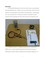
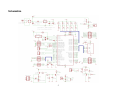
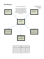
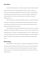
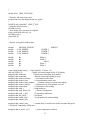
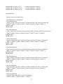
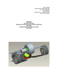
Automatic Temperature Control System
San Jose State University
Department of Mechanical and Aerospace Engineering
ME106 – Fundamentals of Mechatronics
Professor: Burford Furman, Ph.D
Submitted
By
Garry Jackson and Jason Jocson
May 16, 2006
1
Table of Contents
Table of Contents...................................................................................................................................... 2
Summary ................................................................................................................................................... 3
Introduction............................................................................................................................................... 4
Schematics ................................................................................................................................................ 5
Circuit Diagram ........................................................................................................................................ 6
BlockDiagram ........................................................................................................................................... 7
Description................................................................................................................................................ 8
Methodology ............................................................................................................................................. 8
Problems Encountered ............................................................................................................................ 10
Building tips:......................................................................................................................... 10
Conclusion .............................................................................................................................................. 11
References............................................................................................................................................... 13
Appendix................................................................................................................................................. 14
Software Program ................................................................................................................. 14
2
Summary
In the spring 2006 Mechatronics class at San Jose State University, our group designed a
project that implemented what we learned over the course of the semester. It became our goal to
materialize a system that employed a microcontroller, sensors and actuators. In the photograph
below, the microcontroller device on the bottom is connected to a breadboard circuit that
controls the fan speed, depending on the status of the motion detector and temperature sensor.
To implement this project, we segmented the project into terms of software and
hardware. First, we devised a schematic diagram that would control a fan to operate at 3
different speeds. The speed would be controlled by the microcontroller by sending out a +5V
3
signal through a network of transistors which would result at turning on a fan at a particular
speed.
By the end of the project, our group had implemented many topics that we learned
throughout the semester. By using transistor theory, circuit analysis, and software
programming, we were able to implement a microcontroller based automatic temperature control
system.
Introduction
The purpose of this project is to demonstrate how microcontrollers can be used and
applied in a real-world application. One practical use is to incorporate a microcontroller in a
temperature control system that can be used for automatically controlling a rooms’ temperature.
By using a system of sensors and actuators, a microcontroller can act as an active device that
responds to various inputs by sending control signals to other branches of a circuit that controls
their corresponding actuators.
The microcontroller our group decided to use was an Atmega-128 based microcontroller
that was programmed with an Olimex AVR-MT128. Similar to the STK500 board, this unit is
programmable via JTAG ports behind the unit connect to a PC via a USB cable. The MT-128 is
Equipped with an LCD display, capable of outputting status messages, character strings or any
other information a user wishes to display. In addition to the LCD, the MT-128 has other usable
features such as 6 pushbutton switches, a relay and buzzer. As the main component of the
project, this unit controlled an external circuit that would function as a temperature controller,
utilizing a motion detector sensor, a temperature sensor, and a motorized fan.
4
Schematics
5
Circuit Diagram
+5V'
R4
22K
V0
DB4
DB5
DB6
DB7
RS
R/W
E
35
36
37
38
39
40
41
42
3
11
12
13
14
4
5
6
LCD
VCC_BAR
R1
RESISTOR
61
60
59
58
57
56
55
54
64
62
63
D1
LM335/TO92
XTAL1
XTAL2
PA0/AD0
PA1/AD1
PA2/AD2
PA3/AD3
PA4/AD4
PA5/AD5
PA6/AD6
PA7/AD7
TOSC1/PG4
TOSC2/PG3
PC0/A8
PC1/A9
PC2/A10
PC3/A11
PC4/A12
PC5/A14
PC6/A14
PC7/A15
ADC0/PF0
ADC1/PF1
ADC2/PF2
ADC3/PF3
ADC4/TCK/PF4
ADC5/TMS/PF5
ADC6/TD0/PF6
ADC7/TD1/PF7
PB7/OC2/OC1C
PB6/OC1B
PB5/OC1A
PB4/OC0
PB3/MIS0
PB2/MDSI
PB1/SCK
PB0/SS
51
50
49
48
47
46
45
44
B5
VCC_BAR
1
VDD
2
U4
RESET/
17
16
15
14
13
12
11
10
MG1
D2
DIODE
2
R9
19
18
R8
22K
VCC
VCC
24
23
+5V
R7
22K
B4
MOTOR AC
R2
60ohm
Q1
2N3904
AVCC
R3
90ohm
Q2
2N3904
AVREF
Q3
2N3904
GND
GND
20
B3
AGND
22
53
POT
B2
R6
22K
52
21
B1
U2
R5
22K
MEGA128.8MM
U3
1
OUT
+Vcc
GND
Motion Sensor
6
3
2
BlockDiagram
Garry Jackson and
Jason Jocson
3/23/2006
Fan Control Block Diagram
Motion Sensor
Possible chips include
Not found yet
The fan control allow the user to
set the fan to change speeds
automatically depending on if
there is motion in the room and
the temperature difference that is
in the room.
Temperature Sensor
Possible chips include
DS18S20 3pins
AVR MEGA 128
Microcontroller
Motor
This will run at 3 speeds
and two directions which
will be controlled using the
microcontroller, h bridge
and varying the duty cycle.
There will be an set of
switches that will allow the
user to say which speed
they want the fan if different
then the automatic settings.
Optional: An LCD that will
output the temperature of
the room, what speed the
fan is going and which
direction. Also if the motion
sensor is tripped or not.
Temperature Difference
2
4
6
Motion Sensor
Active
Active
Active
4 Deactive
8 Deactive
12 Deactive
7
Fan Speed
1
2
3
1
2
3
Description
The initial function of this project is to simulate an automatic temperature control system that
could be used in closed areas where ambient temperatures fluctuate. However, in order to save
electricity, a motion sensor that is integrated into the circuit is used to activate a variable-speed fan
which operates either at the users desired setting, or an automated setting that is dependent on the
temperature difference of the room’s measured temperature and an internally set temperature
determined by the user.
In the user manual mode, a motion sensor enables the circuit to be set at a specific fan speed to
cool the room. As long as there is a presence that the motion detector senses, the fan will continue
cool the room at its set speed. If the user leaves the room with the fan on, the motion detector will
disable the fan and turn it off to save electricity.
In the automatic mode, a motion sensor will enable the circuit to actuate a fan to cool the room
automatically. If the temperature difference in the room is 1-5 degrees from its set point, the fan will
automatically spin at 1/3 of its speed. If the temperature difference is between 6 -10 degrees from its
set point, the fan will spin at 2/3s of its speed. If the temperature difference is greater than 10 degrees
from the set temperature, the microcontroller will set the fan to its full speed to cool the room the
fastest.
Methodology
When taking on a new electronics project, it is important to carefully organize the methods in
which the project must be performed. Because there can be various systems and subsystems to deal
with, it is best to break the systems down into smaller, manageable tasks to complete. In putting
together our project, we chose to approach it by segmenting it in terms of hardware procedure and
software procedure.
8
When building the temperature control system, I prepared a workspace that could
accommodate the tools, equipment, and materials that were required for the project. By clearing a
large area on my desk, I placed soft absorbing cloth across the workspace so that any loose materials
will not easily roll of the desktop in the event of any parts or pieces becoming loose to bounce and roll
off the desk. The soft material can absorb any stray moving components and catch it before it gets lost.
This prepared me to take the necessary steps in getting ready for the assembly of the project.
Our main source of instruction in building the circuit was to follow the schematic we generated
by using MultiSim. After populating the breadboard with the 2N3904 transistors, and resistors, we
applied +5 voltage through the circuit to simulate the controller sending the voltage coming from the
mictrontroller. We were able to get 3 different voltage outputs to the fan, which would represent a fan
speed at each stage. The transistors would act as an electronic switch that, when triggered, it would
open the 12V supply to the fan.
At each stage, we inserted resistors on 2 of the 3 stages to reduce the voltage going to the fan.
This would result in a Lo, Med, and Hi setting.
The temperature sensor and the motion sensor both operate on +5V and have one output pin.
The Vcc and Ground pins were then connected directly on the breadboard and the output pin was tied
to the microcontrollers input. The Motion sensor was tied to the one of the port pins while the
temperature controller was connected to the ADC. This would allow for the controller to use a closed
feedback system where the temperature sensor would feed a voltage into the ADC and the
microcontroller would compare it to a setpoint temperature fixed inside the microcontroller.
The microcontroller would then take the comparison and determine what speed the fan should
go to by checking against an index of temperature differences. If the measured temperature was within
2 degrees of the setpoint, it would trigger the Lo setting of the fan. If the measured temperature was
within 3-5 degrees of the set temperature, it would trigger the Medium setting of the fan circuit, and
any temperature 6 degrees or greater it would trigger the maximum output (12V) to the fan.
9
Problems Encountered
Building tips:
1. No power – ac voltage is not reaching the circuit. By measuring the voltage across
various resistors, pin ports and IC leads, we were able to troubleshoot and determine the
culprit of not having any power to our circuit
2. Bad soldering – soldering leads onto our sensors and fans may have bad solder joints an
can cause a bad connection for power continuity throughout the circuit
3. Wires go the wrong places – sometimes leads would be placed into the wrong row of a
breadboard and would cause a misconnection or open circuit
4. Wrong part or parts put in the wrong places – the resistors we used may have been
mistaken for a wrong value. Sometimes if we need a 1K resistor, we got mistaken by
reading the color codes as a 10K
5. Polarized parts put in the wrong, way - Transistor pin-out varies, so check the pin-out of
the devices you get. Electrolytic caps often look like a short if the voltage is reversed.
6. Bad parts – even when we confirmed that our circuit was wired up correctly, we were
able to narrow our problem down to a bad part. A defective motion sensor will not
allow the rest of the circuit. After we replaced it, it worked fine.:
In the website http://www.geofex.com/Article_Folders/howto.pdf, the author discusses several tips for
troubleshooting electronic circuits:
•
For NPN transistors used as amplifiers, with no signal, the collector is the most positive
voltage, usually by at least a couple of volts; the base is somewhat lower and the emitter is
invariably 0.5 to 0.7V (0.2 to 0.3 in germanium) lower than the base. If this is not true,
something is fouled up about the biasing on that stage.
•
For PNP transistors used as amplifiers, with no signal, the collector is the most negative
voltage, usually by at least a couple of volts; the base is somewhat higher and the emitter is
10
invariably 0.5 to 0.7V (0.2 to 0.3 in germanium) higher than the base. If this is not true,
something is fouled up about the biasing on that stage.
•
For bipolar (NPN/PNP) transistors, if the collector/base, collector emitter or base/emitter are
exactly the same voltage, either there is a circuit board short or the device is internally shorted
and dead.
•
To check a bipolar transistor, read the collector voltage; short the base to the emitter with a clip
lead. The collector voltage should go up except for cases where the collector is tied to the +
power supply. In that case, the emitter will go down significantly.
•
Measure the power voltages of IC's directly at the pins of the IC
•
Op-amps used as linear amplifiers must have the negative input and the positive input at the
same voltage +/- a few millivolts of the positive input. If this is not true, the op-amp is dead or
the circuit board is fouled up some way (not true if it's used as a comparator!)
•
Op-amp positive and negative inputs and output pins should usually all be between +2 and +7
volts DC with respect to ground in single battery systems for linear amplifier op-amps, not
including some special “rail-to-rail” op-amps, comparator use and some precision rectifiers.
Conclusion
Upon the completion of our project, we were happy that it was able to function correctly. The
circuit design and software debugging were the most difficult to implement, but once it started to work,
the trouble became worthwhile and was very rewarding for our group.
If we had more time to complete the project, we could make a display that would look more
practical, rather than just have some electronic breadboard populated with transistors, resistors and
capacitors. Instead, we can cover the circuit and make a display of a model bedroom that had an
overhead fan with the temperature sensor in the corner of the room. It was an idea to use an 1157
11
automotive bulb to place near the temperature sensor that would simulate heat from the sun to trigger
the the fan to an appropriate speed.
Ultimately, we were satisfied that our project was able to function properly and do what it was
designed to do.
12
References
http://www.geofex.com/Article_Folders/howto.pdf
http://home.iae.nl/users/pouweha/lcd/lcd0.shtml#pin_assignment
http://www.olimex.com/dev/images/avr-mt128-sch.gif
13
Appendix
Software Program
/*****************************************************
This program was produced by the
CodeWizardAVR V1.24.6 Professional
Automatic Program Generator
© Copyright 1998-2005 Pavel Haiduc, HP InfoTech s.r.l.
http://www.hpinfotech.com
e-mail:[email protected]
Project : ME 106 - Fan Controller
Version : 1.0
Date : 5/10/2006
Author : Garry Jackson and Jason Jocson
Company :
Comments:
Reads if there is motion in a room and what the temperature is and determines the speed of the fan.
Output if there is motion, the temperature, and the fan speed to the LCD display.
Chip type
: ATmega128
Program type
: Application
Clock frequency : 8.000000 MHz
Memory model
: Small
External SRAM size : 0
Data Stack size : 1024
*****************************************************/
#include <mega128.h>
#include <delay.h>
#include <stdio.h>
// Alphanumeric LCD Module functions
#asm
.equ __lcd_port=0x15 ;PORTC
#endasm
#include <lcd.h>
// External Interrupt 0 service routine
interrupt [EXT_INT0] void ext_int0_isr(void)
{
// Place your code here
}
#define ADC_VREF_TYPE 0x00
// Read the AD conversion result
unsigned int read_adc(unsigned char adc_input)
{
ADMUX=adc_input|ADC_VREF_TYPE;
// Start the AD conversion
ADCSRA|=0x40;
// Wait for the AD conversion to complete
while ((ADCSRA & 0x10)==0);
ADCSRA|=0x10;
return ADCW;
}
// Declare your global variables here
#define
#define
#define
#define
#define
#define
#define
#define
#define
MOTION_SENSOR
FAN_SPEED1
FAN_SPEED2
FAN_SPEED3
B1
B2
B3
B4
B5
PORTB.3
PORTB.4
PORTB.5
PORTB.6
PINA.0
PINA.1
PINA.2
PINA.3
PINA.4
const unsigned char Intro[] = " Fan Controller Version: 1.0 ";
char lcd_buffer[33];
// Buffer for storing output for the LCD display
unsigned char motionint;
// Motion sensor checking loop number
unsigned char motionrun;
// Motion sensor high returns per loop
unsigned char motion_laststate;
// Last motion sensor state
unsigned char motion_state;
// Current montion sensor state
unsigned char motion_state_number;
// Number of runs in current state reading
unsigned char motion_display;
// Display text for if the display on or off
unsigned char temperature;
// Temperature ADC reading
unsigned char temp_c;
// Temperature in c
unsigned char temp_desire=30;
// Desired Temperature
unsigned char temp_c_diff;
// Temperature Difference
unsigned char fan_speed;
// Fan Speed
unsigned char button_loop;
// Loop number for button reading
unsigned char control_auto;
unsigned char control_state;
// Control State is used for auto mode or manual fan speed
// Fan Speed Temperature Difference
unsigned char m_active_s1=2;
// set the temperature variation
15
unsigned char m_active_s2=4;
unsigned char m_inactive_s1=4;
unsigned char m_inactive_s2=8;
// set the temperature variation
// set the temperature variation
// set the temperature variation
void main(void)
{
// Declare your local variables here
// Input/Output Ports initialization
// Port A initialization
// Func0=In Func1=In Func2=In Func3=In Func4=In Func5=In Func6=Out Func7=In
// State0=T State1=T State2=T State3=T State4=T State5=T State6=0 State7=T
PORTA=0x00;
DDRA=0x40;
// Port B initialization
// Func7=Out Func6=Out Func5=Out Func4=Out Func3=In Func2=In Func1=In Func0=In
// State7=0 State6=0 State5=0 State4=0 State3=T State2=T State1=T State0=T
PORTB=0x00;
DDRB=0xF0;
// Port C initialization
// Func7=In Func6=In Func5=In Func4=In Func3=In Func2=In Func1=In Func0=In
// State7=T State6=T State5=T State4=T State3=T State2=T State1=T State0=T
PORTC=0x00;
DDRC=0x00;
// Port D initialization
// Func7=In Func6=In Func5=In Func4=In Func3=In Func2=In Func1=In Func0=In
// State7=T State6=T State5=T State4=T State3=T State2=T State1=T State0=T
PORTD=0x00;
DDRD=0x00;
// Port E initialization
// Func7=In Func6=In Func5=In Func4=In Func3=In Func2=In Func1=In Func0=In
// State7=T State6=T State5=T State4=T State3=T State2=T State1=T State0=T
PORTE=0x00;
DDRE=0x00;
// Port F initialization
// Func7=In Func6=In Func5=In Func4=In Func3=In Func2=In Func1=In Func0=In
// State7=T State6=T State5=T State4=T State3=T State2=T State1=T State0=T
PORTF=0x00;
DDRF=0x00;
// Port G initialization
// Func4=In Func3=In Func2=In Func1=In Func0=In
// State4=T State3=T State2=T State1=T State0=T
16
PORTG=0x00;
DDRG=0x00;
// Timer/Counter 0 initialization
// Clock source: System Clock
// Clock value: Timer 0 Stopped
// Mode: Normal top=FFh
// OC0 output: Disconnected
ASSR=0x00;
TCCR0=0x00;
TCNT0=0x00;
OCR0=0x00;
// Timer/Counter 1 initialization
// Clock source: System Clock
// Clock value: Timer 1 Stopped
// Mode: Normal top=FFFFh
// OC1A output: Discon.
// OC1B output: Discon.
// OC1C output: Discon.
// Noise Canceler: Off
// Input Capture on Falling Edge
// Timer 1 Overflow Interrupt: Off
// Input Capture Interrupt: Off
// Compare A Match Interrupt: Off
// Compare B Match Interrupt: Off
// Compare C Match Interrupt: Off
TCCR1A=0x00;
TCCR1B=0x00;
TCNT1H=0x00;
TCNT1L=0x00;
ICR1H=0x00;
ICR1L=0x00;
OCR1AH=0x00;
OCR1AL=0x00;
OCR1BH=0x00;
OCR1BL=0x00;
OCR1CH=0x00;
OCR1CL=0x00;
// Timer/Counter 2 initialization
// Clock source: System Clock
// Clock value: Timer 2 Stopped
// Mode: Normal top=FFh
// OC2 output: Disconnected
TCCR2=0x00;
TCNT2=0x00;
OCR2=0x00;
17
// Timer/Counter 3 initialization
// Clock source: System Clock
// Clock value: Timer 3 Stopped
// Mode: Normal top=FFFFh
// Noise Canceler: Off
// Input Capture on Falling Edge
// OC3A output: Discon.
// OC3B output: Discon.
// OC3C output: Discon.
// Timer 3 Overflow Interrupt: Off
// Input Capture Interrupt: Off
// Compare A Match Interrupt: Off
// Compare B Match Interrupt: Off
// Compare C Match Interrupt: Off
TCCR3A=0x00;
TCCR3B=0x00;
TCNT3H=0x00;
TCNT3L=0x00;
ICR3H=0x00;
ICR3L=0x00;
OCR3AH=0x00;
OCR3AL=0x00;
OCR3BH=0x00;
OCR3BL=0x00;
OCR3CH=0x00;
OCR3CL=0x00;
// External Interrupt(s) initialization
// INT0: On
// INT0 Mode: Rising Edge
// INT1: Off
// INT2: Off
// INT3: Off
// INT4: Off
// INT5: Off
// INT6: Off
// INT7: Off
EICRA=0x03;
EICRB=0x00;
EIMSK=0x01;
EIFR=0x01;
// Timer(s)/Counter(s) Interrupt(s) initialization
TIMSK=0x00;
ETIMSK=0x00;
// Analog Comparator initialization
// Analog Comparator: Off
// Analog Comparator Input Capture by Timer/Counter 1: Off
18
ACSR=0x80;
SFIOR=0x00;
// ADC initialization
// ADC Clock frequency: 125.000 kHz
// ADC Voltage Reference: AREF pin
ADMUX=ADC_VREF_TYPE;
ADCSRA=0x86;
// LCD module initialization
lcd_init(16);
// Global enable interrupts
#asm("sei")
lcd_gotoxy(0,0);
lcd_putsf(Intro);
delay_ms(5000);
// goto the top left corner
// write intro message to display
// pause 5seconds
while (1)
{
temperature=read_adc(0);
temp_c=temperature+14;
// Read the ADC value for the temperature sensor
// Convert the ADC temperature value to c
temp_c_diff=temp_c-temp_desire; // Find the difference between measure and desired
temperature
if(control_auto=="YES")
{
motionint=0;
motionrun=0;
while (motionint<4)
{
if(PINB.3==1)
{
motionrun++;
}
motionint++;
delay_ms(250);
}
// If control=yes then check motion sensor and select fan speed
// clear motionint counter for while loop that checks for motion
// clear motionrun counter for while loop that checks for motion
// run this loop until motionint=4 and exit
// check if there is signal on pinb.3 which is the motion sensor
// if the motion sensor is active increment motionrun
// increment motionint for next while loop
// wait .25 seconds before the next check
if (motionrun>0)
// if the motion sensor went hi during one of the 4 checks set
motion_state=active
motion_state="active";
if (motionrun==0)
// if motionrun=0 set it to inactive showing that the sensor did not pick
up movement
motion_state="inactive";
19
// if the current state is not equal to the last state this function will increment motion_state_number
// this if/else is designed for the circuit doesn't go between active inactive over and over because of
// false reasing or someone keeps coming in and out of the room very frequently.
if (motion_laststate!=motion_state)
{
motion_state_number++;
}
else if (motion_laststate!=motion_state && motion_state_number==1)
{
motion_laststate=motion_state;
motion_state_number=0;
}
//This set of if/else look at the desired temp and the temp being read to decide what speed the fan
should be.
if (motion_laststate=="active" && temp_c_diff<=m_active_s1) // Fan Speed temperature
varience if motion sensor is active
fan_speed=3;
else if (motion_laststate=="active" && temp_c_diff<=m_active_s2) // Fan Speed temperature
varience if motion sensor is active
fan_speed=2;
else if (motion_laststate=="active" && temp_c_diff>m_active_s2) // Fan Speed temperature
varience if motion sensor is active
fan_speed=3;
if (motion_laststate=="inactive" && temp_c_diff<=m_inactive_s1) // Fan Speed temperature
varience if motion sensor is active
fan_speed=1;
else if (motion_laststate=="inactive" && temp_c_diff<=m_inactive_s2) // Fan Speed temperature
varience if motion sensor is active
fan_speed=2;
else if (motion_laststate=="inactive" && temp_c_diff>m_inactive_s2) // Fan Speed temperature
varience if motion sensor is active
fan_speed=3;
}
if(fan_speed==1)
{
FAN_SPEED1=1; //turn the low speed on
FAN_SPEED2=0; //turn the medium speed off
FAN_SPEED3=0; //turn the high speed off
}
20
if(fan_speed==2)
{
FAN_SPEED1=0;
FAN_SPEED2=1;
FAN_SPEED3=0;
}
if(fan_speed==3)
{
FAN_SPEED1=0;
FAN_SPEED2=0;
FAN_SPEED3=1;
}
//turn the low speed off
//turn the medium speed on
//turn the high speed off
//turn the low speed off
//turn the medium speed off
//turn the high speed on
if(motion_laststate=="active") // check state of motion_laststate and set motion_display=1 if active
// this shows a 1 or 0 on the display depending on which one is set.
motion_display=1;
else
motion_display=0;
//load the top line into the lcd_buffer for lcd_puts. sprintf replace the %#u with the number in the
//variable temp_c and fan_speed
sprintf(lcd_buffer,"Temp:%3u Speed:%1u",temp_c,fan_speed);
lcd_clear(); //clear the display
lcd_gotoxy(0,0); //move to the top left
lcd_puts(lcd_buffer); //write the buffer to the lcd display
sprintf(lcd_buffer,"MontionSensor:%u",motion_display);
lcd_gotoxy(0,1);
lcd_puts(lcd_buffer);
button_loop=0;
while (button_loop<200)
// button loops runs every 50ms for 200 times and the main loop starts
again
{
if (B1==0)
//if b1 or top button pressed go into auto mode
control_auto="YES";
control_state=1;
if (B2==0)
//if b2 or left button pressed turn fan to speed 1 and auto off
{
control_auto="NO";
fan_speed=1;
control_state=0;
}
if (B3==0)
//if b3 or middle button pressed turn fan to speed 1 and auto off
{
control_auto="NO";
fan_speed=2;
control_state=0;
}
21
if (B4==0)
{
//if b4 or right button pressed turn fan to speed 1 and auto off
control_auto="NO";
fan_speed=3;
control_state=0;
}
delay_ms(50);
button_loop++;
// wait 50ms before next loop start
// increment button_loop for next loop number.
}
};
}
22