1
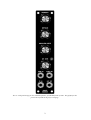
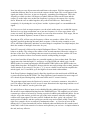
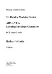
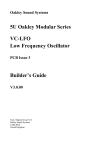
Oakley Sound Systems
5U Oakley Modular Series
Equinoxe
Voltage Controlled Phaser
PCB Issue 5
Builder's Guide
V5.0.02
Tony Allgood B.Eng PGCE
Oakley Sound Systems
CARLISLE
United Kingdom
The 1U wide panel design for the standard Equinoxe for MOTM format systems. The fpd file for this
panel can be found on the project webpage.
2
Introduction
This is the Project Builder's Guide for the issue 5 Equinoxe 5U module from Oakley Sound.
This document contains a basic introduction to the board, a description of the schematic, a full
parts list for the components needed to populate the boards, and a list of the various
interconnections.
For the User Manual, which contains an overview of the operation of the unit, the history of
the various board issues, and the calibration procedures, please visit the main project webpage
at:
http://www.oakleysound.com/equinox.htm
For general information regarding where to get parts and suggested part numbers please see
our useful Parts Guide at the project webpage or http://www.oakleysound.com/parts.pdf.
For general information on how to build our modules, including circuit board population,
mounting front panel components and making up board interconnects please see our generic
Construction Guide at the project webpage or http://www.oakleysound.com/construct.pdf.
3
The issue 5 Equinoxe PCB
This is the issue 5 Oakley Equinoxe behind a black finish Schaeffer panel. Note the use of the optional
Sock4 socket board to facilitate the wiring up of all those sockets.
I have provided space for the four main control pots on the PCB. If you use the specified
16mm Alpha pots and matching brackets, the PCB can be held firmly to the panel without any
additional mounting procedures. The pot spacing is 1.625” and is the same as the vertical
spacing on the MOTM modular synthesiser and most of our other modules.
The design requires plus and minus 15V supplies. The power supply should be adequately
regulated. The current consumption is about 30mA for each rail. Power is routed onto the
PCB by a four way 0.156” MTA156 type connector or the special five way Synthesizers.com
MTA100 header. You could, of course, wire up the board by soldering on wires directly. The
four pins are +15V, ground, earth/panel ground, -15V. The earth/panel connection allows you
to connect the metal front panel to the power supply’s ground without it sharing the modules’
ground line. More about this later.
The PCB has four mounting holes for M3 bolts, one near each corner. These are not required
if you are using the three 16mm pot brackets.
The board size is 143mm (high) x 72mm (deep).
The board has been laid out to accept connection to our Sock4 socket board. This small board
speeds up the wiring of the eight sockets and reduces the chances of mistakes.
Provision is made for the optional fitting of the forthcoming Deep Equinoxe daughter board.
This will add a further four all pass filter sections for a choice of 4, 6 and 8 stage phasing. If
you are not fitting this board you simply link pins 1 and 2 on the DEEP header.
4
Circuit Description
For an excellent starter into phasers and their workings you really should visit R.G. Keen’s
excellent site at: www.geofex.com/Article_Folders/phasers/phase.html.
The Oakley Equinoxe phaser is based around phase shift network built from operational
transconductance amplifiers or OTAs. This type of shifter is not that common compared to the
more numerous designs based on FETs and light sensitive devices. Other units that use the
OTA are the Moog 12-stage phase shifter and the Electro-Harmonix Smallstone. It is the
latter that Jean Michel Jarre used on the Equinoxe album, and the reason behind the Oakley
device’s name. Jarre had his unit modified by Michel Geiss, and the exact modifications are
not known and have become subject to much speculation.
I wanted to create a phaser that was similar in tone to that used on the Jarre albums, but with
more compatibility to modern modular synthesisers. The Equinoxe uses just four all pass
stages to achieve its sound. Each all pass stage is identical. The core of each stage is half an
LM13700 OTA acting as current controlled resistor and inverter in one. This ‘resistor’ acts in
combination with the 6.8nF capacitor to produce an all pass filter whose amplitude response is
flat across the audio spectrum, but importantly, but one with a uneven phase response. At a
certain frequency, determined by the current driving the OTA, the phase shift will be exactly
90 degrees.
You can think of a phase shift as being like a little time delay but for a specific input frequency
only. Here’s another way of looking at phase. Consider a child on a swing and then consider
another child, next to her on the same length swing. He will move at the same frequency as
she does, but it is unlikely that he will have started at the same time in the swing. So as he
goes up, the other swing may be coming down. The two swings are out of phase, but moving
at the same frequency. Only if they started at exactly the same time will they be in phase, or if
he started his swing at a matching point in both their travels.
(OK, its highly unlikely that any two swings will go at the same frequency. Even with the same
length of rope, there are other factors at work to make things more complicated.)
A 90 degree phase shift is equivalent to one swing reaching the top, as the other one flies past
the middle point. Or vice versa...
And a 180 degree phase shift is when one swing is at the top at one end, while the other swing
reaches the top at the other end. Note that the phase shift remains constant so long as both
swings are still moving at the same frequency. Thus the phase shift is still 180 degrees when
the swings are at any point in their travels. For example, when the two swings pass each other
in the middle but going different directions. So the phase shift doesn’t just describe one point
in time, but the whole relationship between two oscillating bodies.
Now, an all pass filter will create a 90 degree phase shift at one frequency only. All other
frequencies will be affected, but to a lesser or greater extent. 90 degrees is important, because
if we cascade two identical all pass networks together we get 180 phase shift at one
frequency. And 180 degrees is exactly half a cycle of oscillation.
5
Now lets take our two all pass networks and listen to the output. Well, the output doesn’t
sound that different. But, let us now mix the output with the input. The overall impact is the
signal gets louder. However, at just one frequency, something special happens. This is the
frequency at which you have 180 degrees of phase difference between the input and the
output. So as the input wave at that one frequency is going up, the output wave is going
down. When the two are added together, they cancel each other out. And in theory,
completely. So by mixing the ‘out of phase’ and the ‘in phase signal’ we can annihilate the
signal.
So if we were to look at output response over the whole audio range we would find it pretty
flat but for a very large notch taken out at just one frequency. So a two stage phaser will
create one notch. By cascading more stages we can create more notches. Four stages, like we
have in the standard Equinoxe, means we have two notches.
By using an OTA will can vary the frequency of these two notches. All the OTAs work
together, hopefully producing the same phase response. (Like the swing example, no two
OTAs will behave identically, and there are other things to complicate our simple analysis, but
that's the wonder of analogue electronics for you)
Each OTA network is followed by a simple Darlington follower. This two transistor circuit
behaves as buffer. The voltage at the emitter of the second transistor follows the voltage on
the base of the first. The nice thing is that no current is stolen by the base, and the OTA can
go about its business with no fear from the outside world pinching its output.
As we have heard the all pass filters are cascaded together to form a short chain. The input
signal enters the chain through C11 and leaves it via the SEND pad which is pin 1 on the
DEEP header. In normal operation the SEND and RETURN pads on the DEEP header are
simply linked together. R14 and R15 then provide the necessary mixing effect at their junction
for the notches to be created. U2a (pins 1, 2, 3) acts as a buffer circuit and also amplifies the
mixed signal, via C10 and R20, up to the high levels associated with modulars.
If the Deep Equinoxe daughter board is fitted the signal leaves the main board at SEND and
re-enters the board at the RETURN. The Deep Equinoxe board contains four more stages of
OTA based all pass filtering along with some buffers and CV control circuitry.
The main input signal enters the Equinoxe by means of a resistative attenuator, also called a
pad. This reduces the input level so as not to cause distortion in the input stage and the rest of
the circuit. R13 and R11 set the 'gain' of the pad.
Q1 and Q4 form a discrete input circuit which buffers the padded input signal. It also provides
the means for some additional mixing from the EMPHASIS pot. The emphasis pot provides a
resonant type effect to be heard, by creating a positive feedback path within the phaser. So not
only do we get the notches we also now get peaks in the response when the output signal
reinforces the input signal. The more positive feedback the more ‘peaky’ the response. Too
much positive feedback, and the system gets carried away and oscillates wildly. Getting this
right is too complex for me to analyse by mathematics alone... so I just let my ears do the
talking (eh??). I played around with various feedback paths and listened to the sound created.
In the end I went for the network of resistors and capacitors you see here. A simple solution in
the end, and very effective.
6
It should be noted that the overall gain of the Equinoxe is less than unity or 0dB, in fact, its
closer to -6dB. This is deliberate although you may find it less than convenient in some
situations where you have a small input signal. The input level is expected to be the typical
modular signal of 5V peak, or 10V peak to peak. With the emphasis turned up high it is
possible to create large resonant peaks at some frequencies. If the through path gain of the
Equinoxe was left at 0dB then these peaks would exceed the maximum allowed output level
and cause distortion. If you are not going to use a 5V peak input, ie. you are connecting your
module to a line level input, then you can increase the gain of the final stage [based around
U2a], and decrease the padding on the input. Lowering R31 will increase the gain of the final
stage, and increasing R11 will decrease the attenuation on the input pad.
The OTAs are all controlled from one current source. This is clever current source though.
Based around Q7 and Q10, it is actually a simple exponential convertor. In other words a
steady increase in base voltage produces a exponential rise in collector current. For every
18mV increase in Q7’s base voltage we double the current sourced by Q10.
The current source is driven from a simple one op-amp inverting summer. Its inputs derived
from either the FREQUENCY pot, the TUNE trimmer and the external CV input
The LFO circuit is quite simple and is based around half of one quad op-amp, U1.
One quarter of the TL074 op-amp, U1b (pins 5, 6, 7) forms part of the integrator. Any
positive voltage applied to the right of R8 will cause the voltage to fall at the output of the opamp. The speed at which the voltage falls is controlled by C8 and the size of the voltage
applied to R8. If the applied voltage is negative the op-amp’s output will rise. It is the
integrator’s output that will be used as the source for the triangle wave output.
Another quarter of the TL074 op-amp (pins 9, 10, 8) is used as a Schmitt trigger. It’s output
is either high at +13V, or low at -13V. If the output of the Schmitt is initially low, it requires
+6V at the output of the integrator to make it go high. The integrator will need to produce an
output of -6V to make the Schmitt go low again.
To make any oscillator you normally require an output to be fed back into the input. Its
positive feedback again. In a standard LFO like this one, the integrator is fed by the output of
the schmitt trigger. Thus, a low at the output of the schmitt causes the integrator to rise.
When the integrator’s output reaches a certain point, the schmitt switches state and the
integrator’s output falls. The schmitt trigger changes state once again, and the process repeats
itself....
The LFO_RATE pot allows only a controlled proportional of the Schmitt’s output voltage to
reach the integrator. If the proportion is large, the voltage on R8 is large, and the integrator
sweeps fast. If the proportion is small, the integrator sweeps slowly. R6 sets the minimum
speed. You can change the value of C8 to get different range of sweep speeds. Setting C8 at
470nF, we can go through the very slow at one cycle per minute to around 10Hz.
The output of the LFO is then split up to do several duties. One branch through R38 goes to
drive the phaser core via the NC (normally closed) lug on the CV input socket. Another
7
branch goes to pin 1 of the INV header and its little 2-way jumper so, if selected, to feed the
LFO OUT socket via R39.
A third branch of the LFO output goes to a simple inverting amplifier based around U1d (pins
12, 13, 14). This simple circuit creates an oppositely going signal at its output, ie. when its
input is +1V, the output is -1V. This inverted output goes to pin 3 of the INV header, which
when the jumper is fitted to short out pins 2 and 3, the inverted output ends up at the LFO
OUT socket.
The fourth branch of the LFO output is sent to the LED driver, based around U1a (pins 1, 2,
3). The bi-colour LED is in the feedback of this op-amp, so whatever current is drawn by R18,
is also put through the LED. If one were to connect the LED and resistor straight across the
LFO output and ground, the LED would be off when the voltage was less than its ‘turn-on’
voltage. This is normally around 2V which is a fair proportion of the 5V output signal. The
old issue one boards did this, and although the LED did give an indication of LED speed, it
would go out for some time. This special driver circuit makes the current through the LED
proportional to the input voltage. So even at small LFO output levels, the LED is still giving
out some light.
A close up of the DEEP header. In the standard Equinoxe you need to link out pins 1 and 2 which
connects the output of the all pass filter cascade to the output circuitry.
8
Issue 5 Equinoxe Parts List
For general information regarding where to get parts and suggested part numbers please see
our useful Parts Guide at the project webpage or http://www.oakleysound.com/parts.pdf.
The components are grouped into values, the order of the component names is of no particular
consequence.
A quick note on European part descriptions. R is shorthand for ohm. K is shorthand for kiloohm. R is shorthand for ohm. So 22R is 22 ohm, 1K5 is 1,500 ohms or 1.5 kilohms. For
capacitors: 1uF = one microfarad = 1000nF = one thousand nanofarad.
To prevent loss of the small ‘.’ as the decimal point, a convention of inserting the unit in its
place is used. eg. 4R7 is a 4.7 ohm, 4K7 is a 4700 ohm resistor, 6n8 is a 6.8 nF capacitor.
Wire Link
With a resistor lead clipping or short length of thin solid core wire solder a wire loop between
pins 1 and 2 of the DEEP header. Pin 1 is the square pin.
Resistors
1% 0.25W metal film types are recommended.
22R
47R
100R
1K
4K7
6K8
7K5
10K
15K
22K
27K
30K
47K
56K
82K
100K
270K
330K
470K
R35, R34, R50, R49
R2
R7, R6
R18, R53, R64, R41, R24, R29, R39, R38, R60
R19, R9, R17
R11
R31
R10, R42, R1, R25, R43, R57, R56, R54, R61, R30, R16
R3
R4
R28, R59, R23, R58, R14, R51, R27, R52
R22, R15
R32, R33, R36
R40, R13
R62
R44, R63, R47, R48, R55, R8, R5, R37, R26, R21
R65
R46
R45, R12, R20
9
Capacitors
1nF 5mm polyester film
6n8 5mm polypropylene film
100nF 5mm polyester film
470nF 5mm polyester film
2u2, 63V electrolytic
22uF, 35V electrolytic
C5
C21, C22, C15, C14
C2, C19, C12, C4, C20
C11, C8, C3, C10
C17, C18
C7, C1, C6, C13, C16, C9
Discrete Semiconductors
BC550 NPN small signal transistor
BC560 PNP small signal transistor
Q1, Q2, Q3, Q5, Q6, Q7, Q8, Q9, Q11, Q12
Q4, Q10
Integrated Circuits
LM13700 dual OTA
TL072 dual op-amp
TL074 quad op-amp
U3, U4
U2
U1
IC sockets are recommended. You need two 16-pin, one 8-pin and one 14-pin DIL sockets.
Potentiometers (Pots)
All pots Alpha 16mm PCB mounted types
10K linear
47K linear
100K log
EMPHASIS
FREQUENCY, MOD_DEPTH
LFO_RATE
Three 16mm pot brackets.
Trimmer
470K horizontal
TUNE
Miscellaneous
Leaded axial ferrite beads
L1, L2
MTA156 4 way header
MTA100 6-way header
PSU
PWR
– Oakley/MOTM power supply
– Synthesizers.com power supply
Molex/MTA 0.1” header 8-way
I/O
– for connecting to sockets
10
Molex/MTA 0.1” housing 8-way
I/O
– for connecting to sockets
3 way 0.1” header
INV
0.1” jumper
Molex/MTA 0.1” housing 2-way
5mm clear LED lens
5mm LED lens securing ring
For fitting to INV
LED – optional connecting technique for the LED.
LED
LED (if lens is not self securing)
Switchcraft 112APC 1/4” sockets
Four off mounted either on the Sock4 board or on panel
Four knobs
Around 2m of insulated multistrand hook up wire.
Components required if using optional Sock4 board
Molex/MTA 0.1” header 8-way
Molex/MTA 0.1” housing 8-way
I/O
I/O
112APC Switchcraft 1/4” socket
SK1, SK2, SK3, SK4
A single wire link is to be fitted to L2 on the Sock4 PCB. L1 is left open.
If using Molex KK you'll also need at least 16 crimp terminals.
Suitable lengths of wire to make up the single 100mm interconnect and two cable ties.
11
Connections
Power connections – MOTM and Oakley
The PSU power socket is 0.156” Molex/MTA 4-way header. Friction lock types are
recommended. This system is compatible with MOTM systems.
Power
Pin number
+15V
Module GND
Earth/PAN
-15V
1
2
3
4
Pin 1 on the I/O header has been provided to allow the ground tags of the jack sockets to be
connected to the powers supply ground without using the module’s 0V supply. Earth loops
cannot occur through patch leads this way, although screening is maintained. Of course, this
can only work if all your modules follow this principle.
Power connections – Synthesizers.com
The PWR power socket is to be fitted if you are using the module with a Synthesizers.com
system. In this case you should not fit the PSU header. The PWR header is a six way 0.1”
MTA, but with the pin that is in location 2 removed. In this way location 3 is actually pin 2 on
my schematic, location 4 is actually pin 5 and so on.
Power
Location number
Schematic Pin number
+15V
Missing Pin
+5V
Module GND
-15V
Not connected
1
2
3
4
5
6
1
2
3
4
5
+5V is not used on this module, so location 3 (pin 2) is not actually connected to anything on
the PCB.
If fitting the PWR header, you will also need to link out pins 2 and 3 of PSU. This connects
the panel ground with the module ground. Simply solder a solid wire hoop made from a
resistor lead clipping to join the middle two pads of PSU together.
12
Building the Equinoxe module using the Sock4 board
This is the simplest way of connecting all the sockets to the main board. The Sock4 board
should be populated in the way described in our construction guide found on the project
webpage. There is only one eight way header and it is to be fitted to the bottom side of the
board.
Do not forget to solder in the wire link L2. Link L1 is left open.
You need to make up only one eight way interconnect. It should be made so that it is 100mm
long.
The prototype unit showing the detail of the board to board interconnect. Here I have used the Molex KK
0.1” system to connect the Sock4 to the main PCB.
13
Hand wiring the sockets
If you have bought Switchcraft 112A sockets you will see that they have three connections.
One is the earth or ground tag. One is the signal tag which will be connected to the tip of the
jack plug when it is inserted. The third tag is the normalised tag, or NC (normally closed) tag.
The NC tag is internally connected to the signal tag when a jack is not connected. This
connection is automatically broken when you insert a jack.
Once fitted to the front panel the ground tags of each socket can be all connected together
with solid wire. I use 0.91mm diameter tinned copper wire for this job. It is nice and stiff, so
retains its shape. A single piece of insulated wire can then be used to connect those connected
earth tags to pin 1 of I/O. Pin 1 is the square solder pad.
All the other connections are connected to the signal or NC lugs of the sockets. The tables
below show the connections you need to make:
Pin
Pad name
Socket Connection
Lug Type
Pin 1
Pin 2
Pin 3
Pin 4
Pin 5
Pin 6
Pin 7
Pin 8
PANEL_GND
LFO_OUT
NC
AUDIO_OUT
NC_LFO
CV_IN
GND
AUDIO_IN
Connect to all sockets
Connect to LFO OUT
No connection
Connect to AUDIO OUT
Connect to CV IN
Connect to CV IN
Connect to AUDIO IN
Connect to AUDIO IN
Earth lugs
Signal lug
14
Signal lug
NC lug
Signal lug
NC lug
Signal lug
Connecting the Bi-colour LED
Using a two way Molex KK housing to connect the bi-colour LED to the circuit board. The LED is held
onto the panel with a clear Cliplite lens, or equivalent.
You may be able to wire the LED directly to the circuit board if the one you have has long
enough leads. However, most of the ones I have seen won't fit directly so I have to use flying
wires to connect the LED to the board. Bi-colour LEDs have just two legs and each one
should go to the solder pad directly beneath it when it is mounted into the panel. I normally
wire it up so that the LED goes red when the output is positive.
You can either solder your connecting wires to the LED's legs or use a MTA or Molex
connector to make the connection.
15
Testing, testing, 1, 2, 3...
Apply power to the unit making sure you are applying the power correctly. The LED should
now throb happily. If it doesn’t turn off, and check all the parts again thoroughly. If your LED
is OK, and there is no smoke rising from the board (yikes!!), then try the LFO rate. It should
control the LED’s flashing. From around one cycle every 30 seconds to around 10 cycles a
second.
Now input an audio signal of some sort, any will do, but a simple sawtooth wave is quite
sufficient. Listen to the audio output, and play with the controls. With all controls to the
minimum setting, sweep the FREQ pot. Do you hear the characteristic phase sweep? If not,
you have got a problem. If yes, now turn up the EMPHASIS. Using the FREQ pot again, does
the sweep have a more metallic ring to it. It’ll probably be a bit louder too.
Now set the FREQ and EMPHASIS pots to their middle position. Turn up the MOD DEPTH.
The LFO should now be modulating the phaser. Check that the RATE affects the speed of the
modulation.
16
Final Comments
If you have any problems with the module, an excellent source of support is the Oakley Sound
Forum at Muffwiggler.com. Paul Darlow and I are on this group, as well as many other users
and builders of Oakley modules.
If you can't get your project to work, then Oakley Sound Systems are able to offer a 'get you
working' service. If you wish to take up this service please e-mail me, Tony Allgood, at my
contact e-mail address found on the website. I can service either fully populated PCBs or
whole modules. You will be charged for all postage costs, any parts used and my time at
25GBP per hour. Most faults can be found and fixed within one hour, and I normally return
modules within a week. The minimum charge is 25GBP plus return postage costs.
If you have a comment about this builder's guide, or have a found a mistake in it, then please
do let me know. But please do not contact me or Paul Darlow directly with questions about
sourcing components or general fault finding. Honestly, we would love to help but we do not
have the time to help everyone individually by e-mail.
Last but not least, can I say a big thank you to all of you who helped and inspired me. Thanks
especially to all those nice people on the Synth-diy, Oakley-Synths and Analogue Heaven
mailing lists and those at Muffwiggler.com.
Tony Allgood at Oakley Sound
Cumbria, UK
© December 2010
No part of this document may be copied by whatever means without my permission.
17