1
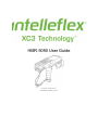
HMR-9090 User Guide
Doc ID: TS-06-0112
Published January 2012
| User Guide | HMR-9090
COPYRIGHT
©2011 Intelleflex Corporation. All rights reserved.
Rights reserved under the copyright laws of the United States.
RESTRICTED RIGHTS LEGEND
Use, duplication, or disclosure by the United States Government is subject to restrictions as set forth in subparagraph
(c)(1)(ii) of the Rights in Technical Data and Computer Software clause at DFARS 252.227-7013.
Notwithstanding any other license agreement that can pertain to, or accompany the delivery of, this computer software, the rights of
the United States Government regarding its use, reproduction, and disclosure are as set forth in the Commercial Computer
Software-Restricted Rights clause at FAR 52.227-19.
IMPORTANT NOTE TO USERS
This software and hardware is provided by Intelleflex Corporation as is and any express or implied warranties, including, but not
limited to, implied warranties of merchantability and fitness for a particular purpose are disclaimed. In no event shall Intelleflex
Corporation or its affiliates, subsidiaries or suppliers be liable for any direct, indirect, incidental, special, exemplary, or consequential
damages (including, but not limited to, procurement of substitute goods or services; loss of use, data, or profits; or business
interruption) however caused and on any theory of liability, whether in contract, strict liability, or tort (including negligence or
otherwise) arising in any way out of the use of this software, even if advised of the possibility of such damage.
Intelleflex Corporation reserves the right to make changes without further notice to any products herein.
TRADEMARKS
Extended Capability RFID and XC3 Technology are trademarks and Intelleflex is a registered trademark of Intelleflex Corporation.
Other products mentioned in this document are trademarks or registered trademarks of their respective holders.
Caution
This device should be operated with a minimum distance of at least 32 cm between its antennas and a person's body in keeping
with RF exposure limits in Council Recommendation 1999/519/EU
HMR-9090 User Guide
DOC ID: TS-06-0111
-2-
January 2012
| User Guide | HMR-9090
Table of Contents
Chapter 1
About This Guide ......................................................................................................... 11
1.1 Introduction ........................................................................................................................................... 11
1.2 Chapter Descriptions .......................................................................................................................... 11
1.3 Notational Conventions...................................................................................................................... 11
1.4 Related Documents and Software .................................................................................................. 11
Chapter 2
Getting Started ............................................................................................................ 12
2.1 Introduction ........................................................................................................................................... 12
2.2 Unpacking the HMR ............................................................................................................................. 12
2.3 Accessories ............................................................................................................................................. 13
2.4 Getting Started ...................................................................................................................................... 13
2.5 Installing and Removing the Main Battery ................................................................................. 14
Installing the Main Battery
Removing the Main Battery
14
14
2.6 Charging the Battery ........................................................................................................................... 15
Charging the Main Battery and Memory Backup Battery
Charging the Main Battery
Charging Spare Batteries
15
16
17
2.7 Starting the HMR .................................................................................................................................. 17
2.8 Calibrating the Screen ........................................................................................................................ 18
2.9 Checking Battery Status ..................................................................................................................... 18
2.10 Battery Management........................................................................................................................... 18
Battery Saving Tips
18
2.11 Stylus......................................................................................................................................................... 18
2.12 HMR Strap ............................................................................................................................................... 19
2.13 Changing the Power Settings............................................................................................................ 20
2.14 Changing the Display Backlight Settings...................................................................................... 20
2.15 Changing the Keypad Backlight Settings ..................................................................................... 20
2.16 Turning the Radios Off ....................................................................................................................... 21
On Devices with Mobile 5.0 AKU 1.0
WLAN Radio
Bluetooth and WWAN Radios
On Devices with Mobile 5.0 AKU 2.2 or higher
21
21
21
21
2.17 Wireless Applications ......................................................................................................................... 22
2.18 ActiveSync ............................................................................................................................................... 23
Chapter 3
Accessories .................................................................................................................... 24
3.1 Introduction ........................................................................................................................................... 24
Keypads
Cradles
HMR-9090 User Guide
DOC ID: TS-06-0111
-3-
January 2012
24
24
| User Guide | HMR-9090
Miscellaneous
Snap-on Modules
24
24
3.2 Keypad...................................................................................................................................................... 25
Keypad Removal
25
3.3 Multi Media Card (MMC) / Secure Device (SD) Card................................................................ 26
3.4 Single Slot Serial/USB Cradle ........................................................................................................... 26
Setup
Battery Charging Indicators
27
28
3.5 Four Slot Ethernet Cradle .................................................................................................................. 29
Setup
Battery Charging Indicators
Ethernet Communication Setup
Installing MobileDox Cradle Manager
Installing iDockIt
HMR Configuration
DHCP Server Configuration
Cradle Configuration
30
30
31
31
31
32
32
32
3.6 Four Slot Charge Only Cradle ........................................................................................................... 35
Setup
Battery Charging Indicators
36
37
3.7 Four Slot Spare Battery Charger ..................................................................................................... 37
Setup
Spare Battery Charging with the Four Slot Spare Battery Charger
Battery Charging Indicators
37
38
38
3.8 Magnetic Stripe Reader ...................................................................................................................... 38
Attaching and Removing
Setup
Battery Charging Indicators
Serial/USB Connection
Using the MSR
39
39
40
40
41
3.9 Cable Adapter Module ........................................................................................................................ 41
Attaching and Removing
Setup
Battery Charging Indicators
Serial/USB Connection
42
42
43
43
3.10 Universal Battery Charger (UBC) Adapter .................................................................................. 43
Inserting and Removing a Battery
Setup
Battery Charging Indicators
44
44
44
3.11 Modem Module...................................................................................................................................... 45
Setup
Connecting to the HMR
Connecting to the Single Slot Serial/USB Cradle
Configuring the HMR for the Modem
Connecting the Modem
Modem Country Setup
Supported Countries
AT Commands
Changing the Initialization String
HMR-9090 User Guide
DOC ID: TS-06-0111
-4-
January 2012
46
46
46
47
49
50
50
50
50
| User Guide | HMR-9090
Basic AT Command Syntax
Commands
52
53
3.12 Serial Communication Setup ............................................................................................................ 56
Setting Up a Connection on the HMR
56
3.13 USB Host Communication Setup ..................................................................................................... 58
3.14 Wall Mounting Bracket and Shelf Slide ........................................................................................ 59
Installing the Wall Mount Bracket
Attaching the Shelf Slide to the Wall Mount Bracket
One Single Slot Cradle/Four Slot Battery Charger
Two Single Slot Cradles/Four Slot Battery Chargers
Four Slot Cradle
Installing the Cradle/Charger on the Bracket
Chapter 4
59
60
60
60
60
61
Operating the HMR..................................................................................................... 62
4.1 Introduction ........................................................................................................................................... 62
4.2 Windows Mobile 5.0 Status Icons ................................................................................................... 62
Status Bar
Command Bar
Speaker Icon
Battery Icon
Connectivity Icon
Time Icon
Instant Message Icon
E-Mail Icon
Multiple Notification Icon
62
63
63
64
64
64
65
65
65
4.3 Locking the HMR ................................................................................................................................... 65
4.4 LED Indicators ....................................................................................................................................... 66
4.5 Keypads.................................................................................................................................................... 66
53-Key Keypad for the HMR
Keypad Special Functions
67
70
4.6 Using the Power Button ..................................................................................................................... 71
4.7 Using a Headset ..................................................................................................................................... 71
4.8 Data Capture .......................................................................................................................................... 71
Laser Scanning
Imaging
Aiming the Imager
Operational Modes
Scanning Considerations
Scanning Bar Codes
Scanning Tips
Scan LED Indicator
71
72
72
72
72
73
74
74
4.9 Resetting the HMR................................................................................................................................ 74
Performing a Warm Boot
Performing a Cold Boot
Waking the HMR
75
75
75
4.10 Bluetooth ................................................................................................................................................. 75
Chapter 5
Bluetooth ....................................................................................................................... 77
HMR-9090 User Guide
DOC ID: TS-06-0111
-5-
January 2012
| User Guide | HMR-9090
5.1 Introduction ........................................................................................................................................... 77
5.2 Adaptive Frequency Hopping .......................................................................................................... 77
5.3 Security .................................................................................................................................................... 77
5.4 Turning the Bluetooth Radio Mode On and Off ......................................................................... 78
Disabling Bluetooth
Enabling Bluetooth
Bluetooth Power States
Cold Boot
Warm Boot
Suspend
Resume
78
78
79
79
79
79
79
5.5 Bluetooth Profiles ................................................................................................................................ 79
5.6 Modes........................................................................................................................................................ 80
Wizard Mode
Explorer Mode
80
81
5.7 Discovering Bluetooth Device(s) .................................................................................................... 82
Bonding with Discovered Device(s)
Renaming a Bonded Device
Deleting a Bonded Device
Accepting a Bond
83
84
85
85
5.8 Discovering Services ........................................................................................................................... 86
File Transfer Services
Create New File or Folder
Delete File
Get File
Put File
Connect to the Internet Using Access Point
Dial-Up Networking Services
Add a Dial-up Entry
OBEX Object Push Services
Send a Picture
Headset Services
Serial Port Services
Personal Area Network Services
IrMC Synchronization Services
87
87
88
88
88
88
88
90
90
91
92
92
93
93
5.9 Bluetooth Settings ................................................................................................................................ 93
Device Info Tab
Services Tab
Dial-Up Networking Service
File Transfer Service
OBEX Object Push Service
Personal Area Networking Service
Serial Port Service
Headset Service
IrMC Synchronization Service
Security Tab
Discovery Tab
Virtual COM Port Tab
Miscellaneous Tab
Chapter 6
93
94
95
95
96
97
97
98
98
98
99
99
100
Wireless Applications ..............................................................................................101
HMR-9090 User Guide
DOC ID: TS-06-0111
-6-
January 2012
| User Guide | HMR-9090
6.1 Introduction ......................................................................................................................................... 101
6.2 Signal Strength Icon........................................................................................................................... 102
6.3 Turning the WLAN Radio On and Off ........................................................................................... 102
6.4 Find WLANs Application .................................................................................................................. 103
6.5 Profile Editor Wizard ........................................................................................................................ 104
Profile ID
Operating Mode
Ad-Hoc
Authentication
Tunneled Authentication
User Certificate Selection
User Certificate Installation
Server Certificate Selection
Credential Cache Options
User Name
Password
Advanced Identity
Encryption
Key Entry Page
Passkey Dialog
IP Address Entry
Transmit Power
Battery Usage
Manage Profiles Application
Changing Profiles
Editing a Profile
Creating a New Profile
Deleting a Profile
Ordering Profiles
Export a Profile
104
105
106
107
108
109
110
110
111
113
113
114
114
116
116
117
119
120
121
122
122
123
123
123
123
6.6 Wireless Status Application............................................................................................................ 124
Signal Strength Window
Current Profile Window
IPv4 Status Window
Wireless Log Window
Saving a Log
Clearing the Log
Versions Window
125
126
127
129
129
129
129
6.7 Wireless Diagnostics Application ................................................................................................. 130
ICMP Ping Window
Trace Route Window
Known APs Window
131
132
133
6.8 Options ................................................................................................................................................... 134
Operating Mode Filtering
Regulatory Options
Band Selection
System Options
Change Password
Export
134
135
136
136
137
137
6.9 Persistence ........................................................................................................................................... 139
HMR-9090 User Guide
DOC ID: TS-06-0111
-7-
January 2012
| User Guide | HMR-9090
6.10 Registry Settings ................................................................................................................................. 139
6.11 Log On/Off Application..................................................................................................................... 139
User Already Logged In
No User Logged In
Chapter 7
139
140
ActiveSync ...................................................................................................................142
7.1 Introduction ......................................................................................................................................... 142
7.2 Installing ActiveSync ......................................................................................................................... 142
7.3 HMR Setup............................................................................................................................................. 142
7.4 Setting Up an ActiveSync Connection on the Host Computer ............................................. 143
7.5 Synchronization with a Windows Mobile 5.0 Device ............................................................ 144
Chapter 8
Application Deployment .........................................................................................147
8.1 Introduction ......................................................................................................................................... 147
8.2 Security .................................................................................................................................................. 147
Application Security
Digital Signatures
Locking Down a HMR
Installing Certificates
Device Management Security
Remote API Security
147
147
147
148
148
149
8.3 Packaging .............................................................................................................................................. 149
8.4 Deployment .......................................................................................................................................... 149
Installation Using ActiveSync
Installation Using Storage Card
Installation Using AirBEAM
Image Update
Creating a Splash Screen
149
149
149
150
150
8.5 XML Provisioning ............................................................................................................................... 151
Creating an XML Provisioning File
XML Provisioning vs. RegMerge and CopyFiles
RegMerge
CopyFiles
151
152
152
152
8.6 Storage ................................................................................................................................................... 153
Random Access Memory
Volatile File Storage (Cache Disk)
Persistent Storage
Application Folder
153
153
153
154
8.7 System Configuration Manager ..................................................................................................... 154
File Types
User Interface
Menu Functions
Parameter State Indicators
Window Status Bar
File Deployment
154
154
155
156
156
156
8.8 Rapid Deployment Client................................................................................................................. 156
8.9 AirBEAM Smart ................................................................................................................................... 157
HMR-9090 User Guide
DOC ID: TS-06-0111
-8-
January 2012
| User Guide | HMR-9090
8.10 Symbol Mobility Developer Kits ................................................................................................... 157
Chapter 9
Staging and Provisioning .......................................................................................158
9.1 Introduction ......................................................................................................................................... 158
9.2 Staging .................................................................................................................................................... 158
RD Client Version 1.9.0
Scanning RD Bar Codes
RD Client Version 3.28
Bar Code Scanning
On-Demand Staging
ActiveSync Connection Mode
Ethernet Connection Mode
Already existing IP Connection Mode
Well-known WLAN Connection Mode
RD Client Main Menu
Client Info
Log Menu
View Log
View Job Log
Set Log Level
Set Job Log Level
Package List
158
159
161
162
164
164
164
164
164
166
166
167
167
168
168
169
169
9.3 Provisioning ......................................................................................................................................... 170
MSP Agent
MSP Agent Main Menu
AirBEAM Smart Client
AirBEAM Package Builder
AirBEAM Smart Client
170
170
176
176
176
Chapter 10 Troubleshooting........................................................................................................186
10.1 Introduction ......................................................................................................................................... 186
10.2 Maintaining the RFID reader ......................................................................................................... 186
10.3 Battery Safety Guidelines ................................................................................................................ 186
10.4 Troubleshooting ................................................................................................................................. 187
10.5 Technical Support .............................................................................................................................. 189
Appendix A Using iDockIt ..............................................................................................................190
Quick Start
How To Start iDockIt
How To Enable iDockIt To Manage Connections
Minimize iDockIt
Exit iDockIt
General Setup Options
Enable iDockIt
Display Status When Cradled
Display Settings When Cradled
Reconnect Delay
USB Cradle Type
Auto-dismiss Error Dialogs
Status Tab
Ethernet Cradle Settings
HMR-9090 User Guide
DOC ID: TS-06-0111
-9-
January 2012
191
191
191
192
192
192
193
193
193
193
193
194
194
195
| User Guide | HMR-9090
Establish Network Connection
Launch Application
Serial Cradle Baud Rate
Direct (Serial/USB) Settings
Launch ActiveSync
Establish Network Connection
Launch Application
Serial Cradle Baud Rate
Modem Cradle Settings
Launch ActiveSync
Establish Network Connection
Launch Application
Choose Connection
Create A New Modem Connection
Edit an Existing Modem Connection
Delete an Existing Modem Connection
195
195
196
196
196
196
197
197
197
197
198
198
198
198
199
199
Appendix B Technical Specifications .........................................................................................200
HMR
Modem Module
200
203
Appendix C Keypad Special Keys.................................................................................................206
Appendix D Regulatory ..................................................................................................................208
HMR-9090 User Guide
DOC ID: TS-06-0111
- 10 -
January 2012
| User Guide | HMR-9090
Chapter 1
1.1
About This Guide
Introduction
This guide provides information about using the HMR-9090.
Screens and windows pictured in this guide are samples and can differ from
actual screens.
1.2
Chapter Descriptions
Topics covered in this guide are as follows:
•
•
•
•
•
•
•
•
•
Chapter 1, About This Guide, information on the HMR-9090 user guide
Chapter 2, Getting Started, charging the HMR battery and resetting the HMR
Chapter 3, Accessories, describes the accessories available for the HMR
Chapter 4, Operating the HMR, how to use the HMR
Chapter 5, Bluetooth, setup Bluetooth on the HMR
Chapter 6, Wireless Applications, configure Wi-Fi and related applications
Chapter 7, ActiveSync, exchange information with a host computer
Chapter 8, Application Deployment, package and deploy applications
Chapter 9, Staging and Provisioning, describes Rapid Deployment, AirBEAM
Smart, and MSP Agent
• Chapter 10, Troubleshooting, provides troubleshooting solutions
1.3
Notational Conventions
The following conventions are used in this document:
• “RFID Reader”, “reader”, or “HMR” refers to the Intelleflex HMR-9090 RFID
reader.
• Italics are used to highlight the following:
o Chapters and sections in this guide
o Related documents
• Bold text is used to highlight the following:
o Dialog box, window and screen names
o Drop-down list and list box names
o Check box and radio button names
o Icons on a screen
o Key names on a keypad
o Button names on a screen
• Bullets (●) indicate:
o Action items
o Lists of alternatives
o Lists of required steps that are not necessarily sequential
• Sequential lists (e.g., those that describe step-by-step procedures) appear as
numbered lists.
1.4
Related Documents and Software
The following documents provide more information about the HMR-9090 reader.
1. HMR-9090 Quick Start Guide, DOC ID: TS-07-1210
2. ActiveSync software, available at: http://www.microsoft.com
HMR-9090 User Guide
DOC ID: TS-06-0111
- 11 -
January 2012
| User Guide | HMR-9090
Chapter 2
2.1
Getting Started
Introduction
This chapter lists the accessories for the HMR and explains how to install and charge the
batteries, replace the strap, and start the HMR for the first time.
2.2
Unpacking the HMR
Carefully remove all protective material from around the HMR and save the shipping
container for later storage and shipping.
Verify that you received all equipment listed below:
•
•
•
•
•
•
HMR
Lithium-ion battery
Strap, attached to the HMR
Stylus, in the stylus silo
HMR-9090 User Guide
HMR-9090 Quick Start Guide
Figure 2-1 HMR
HMR-9090 User Guide
DOC ID: TS-06-0111
- 12 -
January 2012
| User Guide | HMR-9090
2.3
Accessories
Table 2-1: HMR Accessories
Accessory
2.4
Description
Cable Adapter
Module (CAM)
Snap-on required to connect the following cables to the HMR.
1. AC line cord (country-specific) and
power supply, charges the HMR.
2. Auto charge cable, charges the HMR
using a vehicle’s cigarette lighter.
3. DEX cable, connects the HMR to a
vending machine.
4. Serial cable, adds serial communication
capabilities.
5. USB cable, adds USB communication
capabilities.
6. Printer cable, adds printer
communication capabilities.
Four Slot Charge
Only Cradle
Charges the HMR main battery.
Four Slot
Ethernet Cradle
Charges the HMR main battery and synchronizes the HMR with
a host computer through an Ethernet connection.
Four Slot Spare
Battery Charger
Charges up to four HMR spare batteries.
Magnetic Stripe
Reader (MSR)
Snaps on to the HMR and adds magstripe read capabilities.
Modem Module
Enables data communication between the HMR and a host
computer, remotely through the phone lines, and synchronizes
information between the HMR and a host computer.
Multimedia Card
(MMC)
Provides secondary non-volatile storage.
Single Slot
Serial/USB
Cradle
Charges the HMR main battery and a spare battery. It also
synchronizes the HMR with a host computer through either a
serial or a USB connection.
Software
Symbol Mobility Developer Kits available at:
http://support.symbol.com.
Spare lithium-ion
battery
Replacement battery.
Stylus
Performs pen functions.
Universal
Battery Charger
Adapter
Adapts the UBC for use with the Series 9000 batteries.
Wall Mounting
Bracket and
Shelf Slide
Use for wall mounting applications.
Getting Started
In order to start using the HMR for the first time:
HMR-9090 User Guide
DOC ID: TS-06-0111
- 13 -
January 2012
| User Guide | HMR-9090
•
•
•
•
Install the main battery
Charge the main battery and backup battery
Start the HMR
Configure the HMR
The main battery can be charged before or after it is installed. Use one of the spare
battery chargers to charge the main battery (out of the HMR), or one of the cradles to
charge the main battery installed in the HMR.
2.5
Installing and Removing the Main Battery
Installing the Main Battery
Before using the HMR, install a lithium-ion battery by sliding the battery into the HMR as
shown.
Ensure the battery is fully inserted. Two audible clicks can be heard as the battery
is fully inserted. A partially inserted battery may result in unintentional data loss.
When a battery is fully inserted in a HMR for the first time the device boots and powers
on automatically.
Figure 2-2 Installing the Main Battery
Removing the Main Battery
To remove the main battery:
1. Prior to removing the battery, press the red Power button to place the HMR in the
suspend mode.
2. Simultaneously press both primary battery releases. The battery partially ejects
from the HMR.
3. Pause 3-4 seconds while the HMR performs battery removal shutdown.
4. Press the secondary battery release, on top of the battery, and slide the battery
out of the HMR.
HMR-9090 User Guide
DOC ID: TS-06-0111
- 14 -
January 2012
| User Guide | HMR-9090
Figure 2-3 Removing the Main Battery
2.6
Charging the Battery
Charging the Main Battery and Memory Backup Battery
Before using the HMR for the first time, charge the main battery until the amber charge
indicator light remains lit (see Table 2-2 for charge status indications). Charge time is less
than four hours. The HMR can be charged using a cradle, the CAM with a charging
cable, or the MSR with the appropriate power supply.
The HMR is equipped with a memory backup battery which automatically charges from
the fully-charged main battery. When the HMR is used for the first time, the backup
battery requires approximately 15 hours to fully charge. This is also true any time the
backup battery is discharged, which occurs when the main battery is removed for several
hours. The backup battery retains data in memory for at least 30 minutes when the
HMR’s main battery is removed. When the HMR reaches a very low battery state, the
combination of main battery and backup battery retains data in memory for at least 72
hours.
Do not remove the main battery within the first 15 hours of use. If the main battery
is removed before the backup battery is fully charged, data may be lost.
Use the following to charge batteries:
1. Cradles: The HMR slips into the cradles for charging the battery in the HMR (and
spare batteries, where applicable).
a. Single Slot Serial/USB Cradle
b. Four Slot Ethernet Cradle and Four Slot Charge Only Cradles
• Accessories: The HMR’s snap-on accessories provide charging capability, when
used with one of the accessory charging cables.
a. CAM
b. MSR
• Chargers: The HMR’s spare battery charging accessories are used to charge
batteries that are removed from the HMR.
a. Single Slot Serial/USB Cradle
b. Four Slot Spare Battery Charger
c. Universal Battery Charger (UBC)
To achieve the best battery life in HMRs with multiple radios, turn off the radios
that are not being used. This can be accomplished via the SetDevicePower
function in the API (refer to the SMDK Help File for Symbol Mobile Computers).
HMR-9090 User Guide
DOC ID: TS-06-0111
- 15 -
January 2012
| User Guide | HMR-9090
Charging the Main Battery
Charge the main battery in the HMR using a cradle, the CAM with a charging cable, or
the MSR with the appropriate power supply.
Ensure the accessory used to charge the main battery is connected to the
appropriate power source (see Chapter Chapter 3, Accessories for setup
information).
Insert the HMR into a cradle or attach the appropriate snap-on module.
The HMR starts to charge automatically. The amber charge LED, in the Indicator
LED Bar, lights to show the charge status. See Table 2-2 for charging indications.
The main battery usually charges in less than four hours.
HMR-9090 User Guide
DOC ID: TS-06-0111
- 16 -
January 2012
| User Guide | HMR-9090
Table 2-2: HMR LED Charge Indicators
LED
Off
Fast Blinking
Amber
Slow Blinking
Amber
Solid Amber
Indication
HMR not in cradle or the HMR is not attached to the CAM or MSR.
HMR not placed correctly. Charger is not powered.
Error in charging; check placement of the HMR.
HMR is charging.
Charging complete.
Charging Spare Batteries
Use the following three accessories to charge spare batteries:
• Single Slot Serial/USB Cradle
• Four Slot Spare Battery Charger
• UBC Adapter
To charge a spare battery:
• Ensure the accessory used to charge the spare battery is connected to the
appropriate power source (see Chapter Chapter 3, Accessories for setup
information).
• Insert the spare battery into the accessory’s spare battery charging slot with the
charging contacts facing down (over the charging pins) and gently press down on
the battery to ensure proper contact.
• The battery starts to charge automatically. The amber charge LED on the
accessory lights to show the charge status. See Chapter Chapter 3, Accessories
for charging indications for the accessory.
The battery usually fully charges in less than four hours.
2.7
Starting the HMR
Press the red Power button to turn on the HMR. If the HMR does not power on, perform
a cold boot. See Checking Battery Status on page 18 for cold boot procedures.
When a battery is fully inserted in a HMR for the first time, upon the first power up,
the device boots and powers on automatically.
When the HMR is powered on for the first time, it initializes its system. The Symbol
splash screen (Figure 2-4) appears for a short period of time.
Figure 2-4 Symbol Splash Window
HMR-9090 User Guide
DOC ID: TS-06-0111
- 17 -
January 2012
| User Guide | HMR-9090
2.8
Calibrating the Screen
To calibrate the screen so the cursor on the touch screen aligns with the tip of the stylus:
• Using the stylus carefully press and briefly hold the tip of the stylus on the center
of each target that appears on the screen.
To re-calibrate the screen at anytime, press the blue FUNC and ESC keys on the
HMR to launch the calibration screen application.
• Repeat as the target moves around the screen or press ESC to cancel.
2.9
Checking Battery Status
• To check whether the main battery or backup battery in the HMR is charged, tap
Start > Settings > System Tab > Power icon to display the Battery Status
window.
To save battery power, set the HMR to turn off after a specified number of minutes.
To perform a cold boot:
1. Press the primary battery release on the HMR to partially eject the battery from
the HMR.
2. While the battery is partially released, simultaneously press and release the
trigger and power button.
3. Push the battery to fully re-insert it in the HMR. One audible click can be heard as
the battery is fully inserted.
4. The HMR initializes.
2.10
Battery Management
Battery Saving Tips
1.
2.
3.
4.
5.
2.11
Leave the HMR connected to AC power at all times when not in use.
Set the HMR to turn off after a short period of non-use.
Set the display and keyboard backlight to turn off after a short period of non-use.
Turn off all wireless radio activity when not in use.
Power off the HMR when charging to charge at a faster rate.
Stylus
To remove the stylus, pull the stylus cord down and outward to remove the stylus.
HMR-9090 User Guide
DOC ID: TS-06-0111
- 18 -
January 2012
| User Guide | HMR-9090
Figure 2-5 Removing the Stylus
Use the HMR stylus for selecting items and entering information. The stylus functions as
a mouse.
1. Tap: Touch the screen once with the stylus to press option buttons and open
menu items.
2. Tap and Hold: Tap and hold the stylus on an item to see a list of actions available
for that item. On the pop-up menu that appears, tap the action to perform.
3. Drag: Hold the stylus on the screen and drag across the screen to select text and
images. Drag in a list to select multiple items.
2.12
HMR Strap
The strap may be moved to either the left or right side of the HMR to suit user
preferences.
To reposition the strap:
1.
2.
3.
4.
HMR-9090 User Guide
DOC ID: TS-06-0111
Disconnect the metal clip at the handle.
Open strap loop and slide the handstrap through the loop.
Slide the loop out of the connector post.
Reverse the procedure to re-attach the strap. Two strap connectors are provided
on the HMR’s main body. The handstrap may be attached to either connector.
- 19 -
January 2012
| User Guide | HMR-9090
Figure 2-6 Reposition the Strap
2.13
Changing the Power Settings
To set the HMR to turn off after a short period of non-use:
• Tap Start > Settings > System tab > Power icon > Advanced tab.
• Select On battery power: Turn off device if not used for: check box and select
a value from the drop-down list box.
• Tap OK.
2.14
Changing the Display Backlight Settings
To change the display backlight settings in order to conserve more battery power:
• Tap Start > Settings > System tab > Backlight icon > Battery Power tab.
• Select the On battery power: Disable backlight if not used for: check box and
select a value from the drop-down list box.
• Tap the Brightness tab.
• Tap the Disable backlight check box to completely turn off the display backlight.
• Use the slider to set the brightness of the backlight. Set it to a low value to save
battery power.
• Tap OK.
2.15
Changing the Keypad Backlight Settings
To change the keypad backlight settings in order to conserve more battery power:
• Tap Start > Settings > System tab > Keylight icon > Battery Power tab.
• Select the On battery power: Disable keylight if not used for: check box and
select a value from the drop-down list box.
• Tap the Advanced tab.
• Tap the Disable keylight check box to completely turn off the display backlight.
• Tap OK.
HMR-9090 User Guide
DOC ID: TS-06-0111
- 20 -
January 2012
| User Guide | HMR-9090
2.16
Turning the Radios Off
On Devices with Mobile 5.0 AKU 1.0
WLAN Radio
To turn off the WLAN radio tap the Signal Strength icon at the bottom of the Today
screen and select Disable Radio. A red X appears across the icon indicating that the
radio is disabled (off).
To turn the radio back on, tap the Signal Strength icon at the bottom of the Today
screen and select Enable Radio. The red X disappears from the icon indicating that the
radio is enabled (on).
Bluetooth and WWAN Radios
The Flight Mode feature only turns off the WWAN and Bluetooth radios. The
WLAN radio must be turned off separately.
To turn off the Bluetooth and WAN radios:
• Tap the Connectivity icon
(on non-WAN devices) or the Antenna/Signal icon
(on WAN devices) and select Turn On Flight Mode.
To turn the Bluetooth and WAN radios back on:
• Tap the Connectivity icon
(on non-WAN devices) or the Antenna/Signal icon
(on WAN devices) and select Turn Off Flight Mode.
On Devices with Mobile 5.0 AKU 2.2 or higher
Windows Mobile 5.0 devices with AKU 2.2 or higher include Wireless Manager, which
provides a simple method of enabling, disabling, and configuring all the device’s wireless
capabilities in one place.
To open Wireless Manager, tap the Connectivity icon.
HMR-9090 User Guide
DOC ID: TS-06-0111
- 21 -
January 2012
| User Guide | HMR-9090
Figure 2-7 Opening Wireless Manager
Select Wireless Manager.
Figure 2-8 Wireless Manager Window
To enable or disable a wireless connection, tap its blue bar.
To enable or disable all wireless connections, tap and hold the All bar.
To configure settings for a connection, tap Menu.
Figure 2-9 Wireless Manager Menu
2.17
Wireless Applications
Wireless Local Area Networks (WLANs) allow HMRs to communicate wirelessly and
send captured data to a host device in real time. Before using the HMR on a WLAN, the
HMR-9090 User Guide
DOC ID: TS-06-0111
- 22 -
January 2012
| User Guide | HMR-9090
facility must be set up with the required hardware to run the wireless LAN and the HMR
must be configured. Refer to the documentation provided with the access points (APs) for
instructions on setting up the hardware.
To configure the HMR, a set of wireless applications provide the tools to configure and
test the wireless radio in the HMR. The Wireless Application menu on the task tray
provides the following wireless applications:
1.
2.
3.
4.
5.
6.
7.
Wireless Status
Wireless Diagnostics
Find WLANs
Manage Profiles
Options
Enable/Disable Radio
Log On/Off
Tap the Signal Strength icon to display the Wireless Applications menu.
Figure 2-10 Wireless Applications Menu
For more information refer to Chapter 6.
2.18
ActiveSync
To communicate with various host devices, install Microsoft ActiveSync (version 4.1 or
higher) on the host computer. Use ActiveSync to synchronize information on the HMR
with information on the host computer. Changes made on the HMR or host computer
appear in both places after synchronization.
ActiveSync software:
• Allows working with HMR-compatible host applications on the host computer.
ActiveSync replicates data from the HMR so the host application can view, enter,
and modify data on the HMR.
• Synchronizes files between the HMR and host computer, converting the files to
the correct format.
• Backs up the data stored on the HMR. Synchronization is a one-step procedure
that ensures the data is always safe and up-to-date.
• Copies (rather than synchronizes) files between the HMR and host computer.
• Controls when synchronization occurs by selecting a synchronization mode, e.g.,
set to synchronize continually while the HMR is connected to the host computer,
or set to only synchronize on command.
• Selects the types of information to synchronize and control how much data is
synchronized.
Additional information on ActiveSync is located in Chapter 7.
HMR-9090 User Guide
DOC ID: TS-06-0111
- 23 -
January 2012
| User Guide | HMR-9090
Chapter 3
3.1
Accessories
Introduction
The series 9000 accessories provide a wide variety of product support capabilities.
Accessories include cradles, keypads, Magnetic Stripe Reader (MSR) and Cable Adapter
Module (CAM) snap-on, four slot spare battery charger, headphone, Multimedia Card
(MMC), Secure Device (SD) card, Universal Battery Charger (UBC) adapter, and wall
mounting bracket and shelf slide.
Keypads
The HMR has interchangeable modular keypads. However, only the 53-Key RFID keypad
can be used with the HMR. The modular keypad can be changed in the field as
necessary.
• 53-key RFID keypad
Cradles
Single Slot Serial/USB cradle charges the HMR main battery and a spare battery.
It also synchronizes the HMR with a hot computer through either a serial or a USB
connection.
• Four Slot Charge Only cradle charges the HMR main battery.
• Four Slot Ethernet cradle charges the HMR main battery and synchronizes the
HMR with a host computer through an Ethernet connection.
Miscellaneous
1. Four Slot Spare Battery Charger charges up to four HMR spare batteries.
2. Headphone can be used in noisy environments.
3. Modem Module enables data communication between the HMR and a host
computer, remotely through the phone lines, and synchronizes information
between the HMR and a host computer.
4. Multimedia Card (MMC) provides secondary non-volatile storage. (An SD card
may also be used.)
5. UBC adapter adapts the UBC for use with the HMR batteries.
6. Wall Mounting Bracket and Shelf Slide can be used for wall mounting
applications.
Snap-on Modules
• MSR connects on to the HMR and adds magstripe read capabilities.
• CAM connects on to the HMR and is used to connect cables to the HMR.
Both of the snap-on modules use the cables listed below:
•
•
•
•
•
•
HMR-9090 User Guide
DOC ID: TS-06-0111
AC line cord (country-specific) and power supply, charges the HMR.
Auto charge cable, charges the HMR using a vehicle cigarette lighter.
DEX cable, connects the HMR to a vending machine.
Serial cable, adds serial communication capabilities.
USB cable, adds USB communication capabilities.
Printer cable, adds printer communication capabilities.
- 24 -
January 2012
| User Guide | HMR-9090
3.2
Keypad
The HMR has a modular keypad. The modular keypad can be removed in the field as
necessary. Keypad removal is required to replace the MMC card.
Do not remove the keypad while the HMR is on and do not operate the HMR with
the keypad detached. Follow proper Electro-Static Discharge (ESD) precautions
to avoid damaging the MMC and SD card. Proper ESD precautions include, but
are not limited to, working on an ESD mat and ensuring that the operator is
properly grounded.
Keypad Removal
• Press the Power button to suspend the HMR.
• Remove the two keypad screws. Slide the keypad down and lift up.
Figure 3-1 Removing the Keypad
Do not apply more than 4 in-lbs of torque when tightening the keypad screws.
• Replace the keypad and re-attach using the two screws.
Figure 3-2 Installing the Keypad
• Perform a cold boot.
HMR-9090 User Guide
DOC ID: TS-06-0111
- 25 -
January 2012
| User Guide | HMR-9090
3.3
Multi Media Card (MMC) / Secure Device (SD) Card
The MMC provides secondary non-volatile storage. The MMC is located under the
keypad (see Figure 3-1 on page 25).
SD cards are inter-operable with MMC cards and can also be used in HMRs.
Do not remove the keypad while the HMR is on and do not operate the HMR with
the keypad detached. Follow proper ESD precautions to avoid damaging the
MMC/SD. Proper ESD precautions include, but are not limited to, working on an
ESD mat and ensuring that the operator is properly grounded.
To insert the MMC/SD card:
• Press the Power button to suspend the HMR.
• Remove the two keypad screws and slide the keypad down and lift off (see Figure
3-1 on page 25).
• Lift the MMC/SD retaining door.
• Position the MMC/SD card, with the contacts down, into the MMC/SD holder. The
MMC/SD card corner notch fits into the holder only one way.
• Snap the retaining door closed.
Figure 3-3 Inserting the MMC/SD
Do not apply more than 4 in-lbs of torque when tightening the keypad screws.
• Replace the keypad and re-attach using the two screws (see Figure 3-2 on page
25).
• Perform a warm boot.
3.4
Single Slot Serial/USB Cradle
Ensure that you follow the guidelines for battery safety described in Battery Safety
Guidelines on page 186.
This section describes how to set up and use a Single Slot Serial/USB cradle with the
HMR. For serial and USB communication setup procedures see Serial Communication
Setup on page 56.
HMR-9090 User Guide
DOC ID: TS-06-0111
- 26 -
January 2012
| User Guide | HMR-9090
Figure 3-4 Single Slot Serial/USB Cradle
Do not place coins, keys, or paper clips in the cradle well.
The Single Slot Serial/USB Cradle:
Provides 15VDC power for operating the HMR.
Provides serial and USB ports for data communication between the HMR and a host
computer or other serial devices (e.g., a printer).
When a HMR with Microsoft Mobile 5.0 is placed in the cradle and an ActiveSync
connection is made, the WLAN radios are disabled. This is a Microsoft security
feature to prevent connection to two networks at the same time.
Synchronizes information between the HMR and a host computer. (With customized
or third party software, it can also be used to synchronize the HMR with corporate
databases.)
Charges the HMR’s main battery.
Charges a spare battery.
Setup
Use only a Symbol approved power supply output rated 12 VDC and minimum 3.3
A. Use of an alternative power supply will void the product warranty and may
cause product damage.
The cradle requires a dedicated port on the host. Select either serial or USB for
communications. Do not connect the cradle to both serial and USB ports.
HMR-9090 User Guide
DOC ID: TS-06-0111
- 27 -
January 2012
| User Guide | HMR-9090
Figure 3-5 Single Slot Cradle Power/Serial Connections
Figure 3-6 Single Slot Cradle Power/USB Connections
Battery Charging Indicators
The Single Slot Serial/USB Cradle can charge the HMR’s main battery and a spare
battery simultaneously. The HMR’s amber charge LED, located in the Indicator LED Bar,
shows the status of the battery charging in the HMR. See Table 2-2 on page 17 for
charging status indications. The amber spare battery charging LED on the cradle (see
Figure 3-4 on page 27) shows the status of the spare battery charging in the cradle. See
Table 3-1 for charging status indications. Batteries usually charge in less than four hours.
Table 3-1 Spare Battery LED Charging Indicators
Spare Battery LED
(on cradle)
Off
Fast Blinking Amber
Slow Blinking Amber
Solid Amber
HMR-9090 User Guide
DOC ID: TS-06-0111
Indication
No spare battery in well; spare battery not placed
correctly; cradle is not powered.
Error in charging; check placement of spare battery.
Spare battery is charging.
Charging complete.
- 28 -
January 2012
| User Guide | HMR-9090
3.5
Four Slot Ethernet Cradle
Ensure that you follow the guidelines for battery safety described in Battery Safety
Guidelines on page 186.
This section describes how to set up and use a Four Slot Ethernet cradle with the HMR.
For cradle communication setup procedures see Ethernet Communication Setup on page
31.
Figure 3-7 Four Slot Ethernet Cradle
Do not place coins, keys, or paper clips in cradle well.
The Four Slot Ethernet cradle:
• Provides 12VDC power for operating the HMR.
• Enables data communication between the HMR (up to four) and a host computer,
over an Ethernet network (using a standard 10Base-T Ethernet cable).
• Synchronizes information between the HMR and a host computer. (With
customized or third party software, it can also be used to synchronize the HMR
with corporate databases.)
• Simultaneously charges up to four batteries in the HMR.
HMR-9090 User Guide
DOC ID: TS-06-0111
- 29 -
January 2012
| User Guide | HMR-9090
Table 3-2 Communication LED
Status
Off
Solid Red
Flashing Green
Slow Flashing Red
Fast Flashing Red
Solid Green
ALL LEDs Flashing Red
Indication
HMR is not in cradle; HMR not placed correctly; cradle is
not powered.
HMR is present, but communication has not started.
HMR is in the cradle, and communicating with the host
computer.
Error, communication did not start.
Warning: Terminal inactivity time-out. The terminal did not
finish data synchronization or had an open connection for
more than 15 minutes. This time is programmable in the
cradle flash parameters.
Terminal is present in the slot and communication is
complete.
Failed automatic cradle configuration via local DHCP
Service.
Setup
Use only a Symbol approved power supply output rated 12 VDC and minimum 9
A. Use of an alternative power supply will void the product warranty and may
cause product damage.
The Four Slot Ethernet cradle must be connected to a power source and to an
Ethernet Hub (when applicable).
Figure 3-8 Four Slot Ethernet Cradle Power Connection
Battery Charging Indicators
The HMR’s amber charge LED, located in the Indicator LED Bar, shows the status of the
battery charging in the HMR. See Table 2-2 on page 17 for charging status indications.
The battery usually charges in less than four hours.
HMR-9090 User Guide
DOC ID: TS-06-0111
- 30 -
January 2012
| User Guide | HMR-9090
Ethernet Communication Setup
To establish a connection between the HMR and the host computer to communicate over
an Ethernet network, perform the following:
1.
2.
3.
4.
5.
6.
Install MobileDox Cradle Manager
Install iDockIt
Configure the HMR
Configure the host computer
Configure the DHCP server
Configure the cradle.
Installing MobileDox Cradle Manager
MobileDox Cradle Manager is used only when establishing a connection using
the Four Slot Ethernet cradle.
The Cradle Management software features:
• View cradles that are attached to the network via MobileDox Net
• View cradle status
• Modify cradle settings including:
o IP address settings
o DNS and WINS settings
o Identification settings
o USB port specific settings
• Restart cradles connected to the network via MobileDox Net
• Update the firmware of MobileDox Net.
To install the Cradle Management Software on the host computer, download the latest
version of the software from http://support.symbol.com. Refer to the instructions included
with the software.
Installing iDockIt
iDockIt is a connection utility which manages activities between the HMR and a
connected Ethernet cradle. For more information on the utility, see the documentation
provided with iDockIt.
iDockIt features:
1. The ability to manage multiple cradle profiles. iDockIt auto-detects the cradle
communication type and behaves accordingly.
2. Integrated modem capabilities using TAPI interface.
3. Runs as a tray application, and always runs in the background.
4. The ability to configure settings within the application.
5. Options to change parameters upon docking (with or without settings time-out).
6. The ability to force synchronization events.
7. The ability to disable WLAN connection on the device to ensure synchronization is
performed via dock.
8. Management of multiple connection types without losing settings.
On HMRs with OEM version lower than 28, the iDockIt installation file to install iDockIt on
the HMR can be downloaded from http://support.symbol.com to the host computer.
Follow the instructions provided with the iDockIt software to install iDockIt onto the HMR.
On HMRs with OEM version 28 and higher, the iDockIt installation file is loaded on the
HMR. To install iDockIt:
1. Open File Explorer.
2. Navigate to the Application directory.
3. Tap the file: IDOCKIT_4.02.05.2_MC90XX_WM5.cab
HMR-9090 User Guide
DOC ID: TS-06-0111
- 31 -
January 2012
| User Guide | HMR-9090
iDockIt installs on the HMR. Follow the onscreen instruction.
Refer to Appendix A, Using iDockIt for instructions on configuring and using iDockIt.
HMR Configuration
Inserting the HMR into the cradle provides direct-connect Remote Access Service (RAS)
service. Configure each HMR for use with the cradle, just as any remote client would be
configured to connect to an Internet Service Provider (ISP). The computer COM port
setting was set to USB during the iDockIt installation procedure.
DHCP Server Configuration
If you use a DHCP server to distribute IP addresses and other network parameters, the
server setup should include the following:
•
•
•
•
•
IP address pool (1 or 5 IP address per cradle)
Router/gateway address
One or more DNS server addresses
One or more WINS server addresses
Subnet mask
To assign the initial cradle IP address, you can either use a DHCP server, as
shown above, or use the MobileDox Cradle Manager (see Installing MobileDox
Cradle Manager on page 31). The DHCP server is the preferred method.
Cradle Configuration
The MobileDox Cradle Manager allows you to setup the Device IP Address and modify
cradle settings. See Installing MobileDox Cradle Manager on page 31 for instructions to
download and install the software. See Figure 3-7 on page 29 for instructions on Four
Slot Ethernet cradle connections.
Setting the Device IP Address
By default, the cradle uses DHCP to obtain its IP address. However, if DHCP fails, the
Cradle Manager can assign an IP address.
This is used if the cradle is connected to the network, but fails to appear in
MobileDox. Enter the hardware device (MAC) address to locate the cradle and
assign it a new IP address.
To set the IP address:
1. Launch the MobileDox Cradle Manager on the host computer.
2. Click File > Set IP Address of Unlisted Device. The Set IP Address window
appears:
Figure 3-9 Set IP Address Window
3. Enter the appropriate MAC Address and IP address.
4. Click OK.
HMR-9090 User Guide
DOC ID: TS-06-0111
- 32 -
January 2012
| User Guide | HMR-9090
Modifying Cradle Settings
•
•
•
•
Launch the MobileDox Cradle Manager on the host computer.
Select the name of the cradle you want to configure from the list.
Click Device > Modify Settings.
Use the General Settings tab to modify the identification settings of the cradle.
Figure 3-10 Cradle Settings Window – General Settings Tab
Table 3-3 Cradle Settings – General Settings Fields
Field
Device Name
Custom String
Require Admin
Privileges to Modify
Settings check box
Description
A text string used to describe the MobileDox device. Any 15character string may be entered.
A text string for any desired usage (examples are: location,
asset ID, etc.). Any 15-character string may be entered.
Selecting this check box requires users to have
administrative privileges in order to modify MobileDox
settings. Administrative privileges are validated using
standard Windows authentication.
• Use the TCP/IP Settings tab to modify the DNS and WINS identification settings
of the cradle.
HMR-9090 User Guide
DOC ID: TS-06-0111
- 33 -
January 2012
| User Guide | HMR-9090
Figure 3-11 Cradle Settings Window – TCP/IP Settings Tab
Table 3-4 Cradle Settings – TCP/IP Settings Fields
Field
Description
Use DHCP
If check box is selected, necessary
information is retrieved from the DHCP
server. If check box is not selected, static
configuration is used (information needs
to be entered).
The IP address that MobileDox uses
when communicating on the network.
The subnet mask that MobileDox uses
when communicating on the network.
The IP address that MobileDox uses to
send non-local IP network data.
The IP address of a server(s) that can
resolve Internet names into IP addresses.
The IP address of a server(s) that can
resolve Windows network names into IP
addresses. This field must be populated
correctly when using ActiveSync.
IP Address
Subnet Mask
Gateway Address
DNS Address
WINS Address
• Use the Port Settings tab to modify the USB port settings of the cradle.
HMR-9090 User Guide
DOC ID: TS-06-0111
- 34 -
January 2012
| User Guide | HMR-9090
Figure 3-12 Cradle Settings Window – Port Settings Tab
Table 3-5 Cradle Settings – Port Settings Fields
Field
Port Name
IP Address
Use DHCP to
obtain IP Address
check box
Use NAT check
box
Description
A text string used to describe the device attached to the port.
Any 15-character string can be entered.
You can specify up to four port names, one for each of the
cradle’s slots.
The IP address assigned to the cradled device. There should be
one IP address per cradle slot. This box is disabled for all
devices if DHCP is used to obtain the IP address.
The cradle uses DHCP to obtain an IP address for the
handheld.
Unchecking this selection allows the cradle to use Static IP
address for the handheld.
The cradle uses Network Address Translation (NAT) when
forwarding handheld traffic onto the network. No IP addresses
are necessary for the handhelds. This must be disabled when
using ActiveSync.
• Click OK.
3.6
Four Slot Charge Only Cradle
Ensure that you follow the guidelines for battery safety described in Battery Safety
Guidelines on page 186.
This section describes how to set up and use a Four Slot Charge Only cradle with the
HMR.
HMR-9090 User Guide
DOC ID: TS-06-0111
- 35 -
January 2012
| User Guide | HMR-9090
Figure 3-13 Four Slot Charge Only Cradle
Do not place coins, keys, or paper clips in cradle well.
The Four Slot Charge Only cradle:
• Provides 12VDC power for operating the HMR.
• Simultaneously charges up to four batteries in the HMR.
Setup
Use only a Symbol approved power supply output rated 12 VDC and minimum 9
A. Use of an alternative power supply will void the product warranty and may
cause product damage.
HMR-9090 User Guide
DOC ID: TS-06-0111
- 36 -
January 2012
| User Guide | HMR-9090
Figure 3-14 Four Slot Charge Only Cradle Power Connection
Battery Charging Indicators
The HMR’s amber charge LED, located in the Indicator LED Bar, shows the status of the
battery charging in the HMR. See Table 2-2 on page 17 for charging status indications.
The battery usually charges in less than four hours.
3.7
Four Slot Spare Battery Charger
Ensure that you follow the guidelines for battery safety described in Battery Safety
Guidelines on page 186.
This section describes how to set up and use the Four Slot Spare Battery Charger to
charge up to four spare batteries.
Figure 3-15 Four Slot Spare Battery Charger
Setup
Use only a Symbol approved power supply output rated 15 VDC and minimum 5
A. Use of an alternative power supply will void the product warranty and may
cause product damage.
HMR-9090 User Guide
DOC ID: TS-06-0111
- 37 -
January 2012
| User Guide | HMR-9090
Figure 3-16 Four Slot Spare Battery Charger Power Connection
Spare Battery Charging with the Four Slot Spare Battery Charger
1. Connect the charger to a power source as shown in Figure 3-16.
2. Insert the battery into a spare battery charging slot and gently press down on the
battery to ensure proper contact.
Battery Charging Indicators
An amber LED is provided on each battery charging well (see Figure 3-15 on page 37).
See Table 3-6 on page 38 for charging status indicators.
The battery usually charges in less than four hours.
Table 3-6 Spare Battery LED Charging Indicators
LED
Off
Fast Blinking Amber
Slow Blinking Amber
Solid Amber
3.8
Indication
No spare battery in slot; spare battery not placed correctly;
cradle is not powered.
Error in charging; check placement of spare battery.
Spare battery is charging.
Charging complete.
Magnetic Stripe Reader
This section describes how to set up and use the snap-on MSR with the HMR. The MSR
snaps on to the bottom of the HMR and can be easily removed when not in use.
Figure 3-17 Magnetic Stripe Reader
When attached to the HMR, the MSR:
HMR-9090 User Guide
DOC ID: TS-06-0111
- 38 -
January 2012
| User Guide | HMR-9090
• Provides power for operating the HMR, with the appropriate power connection.
• Allows the HMR to capture data from magnetic stripe cards. (To download MSR
data capture software, visit: http://support.symbol.com.)
When a HMR is connected to a host computer through the MSR and an
ActiveSync connection is made, the WLAN radio is disabled. This is a Microsoft
security feature to prevent connection to two networks at the same time.
• Provides serial connection through the serial pass-through port for communication
with a serial device, such as a host computer. For communication setup
procedures, see Serial Communication Setup on page 56.
• Provides USB connection through the USB pass-through port for communication
with a USB device, such as a host computer. For communication setup
procedures, see Serial Communication Setup on page 58.
• Charges the HMR’s battery, when used with the appropriate power supply.
Attaching and Removing
To attach, snap the MSR onto the bottom of the HMR.
Figure 3-18 Attaching the MSR
To remove, squeeze the latch grips and pull the MSR from the HMR.
Remove the MSR from the bottom of the HMR before using a cradle for charging
and communication.
Setup
Use only a Symbol approved power supply rated 12 VDC and minimum 3.3 A.
Use of an alternative power supply will void the product warranty and may cause
product damage.
HMR-9090 User Guide
DOC ID: TS-06-0111
- 39 -
January 2012
| User Guide | HMR-9090
Figure 3-19 MSR Power Connection
Figure 3-20 MSR Serial/USB Connection
Battery Charging Indicators
To charge the HMR’s battery through the MSR, connect the power supply to the MSR
(see Figure 3-19 on page 40), then attach the MSR to the HMR. The HMR begins
charging automatically.
Batteries must be charged within the 32° to 104° F (0° to +40° C) ambient
temperature range.
The HMR’s amber charge LED, located in the Indicator LED Bar, shows the status of the
battery charging in the HMR. See Table 2-2 on page 17 for charging status indications.
The battery usually charges in less than four hours, if the HMR is not in use.
Serial/USB Connection
The MSR can connect to and communicate with a serial/USB device, such as a printer or
host computer, through its serial port. See Serial Communication Setup on page 56 for
the host computer communication setup procedure.
To connect the MSR to a serial/USB device, connect one end of the serial device cable
into the serial port on the MSR and the other end into the serial/USB port on the device.
HMR-9090 User Guide
DOC ID: TS-06-0111
- 40 -
January 2012
| User Guide | HMR-9090
Using the MSR
The MSR9000 sample application is designed to work with the MSR. This sample
application illustrates how an application should handle MSR inputs (refer to the Symbol
Application Guide for Symbol Devices).
The MSR does not need to be attached to the power supply to read magnetic
stripes.
To use the MSR:
• Attach the MSR to the HMR (see Attaching and Removing on page 39).
• Power on the HMR.
• Tap Start > 9000 Demo > Test Apps > MSR 9000 or MSR Cameo to start the
sample application.
• Swipe the magnetic stripe card through the MSR, ensuring the magnetic stripe on
the card faces the HMR. The card may be swiped in either direction, from left to
right or from right to left. For best results, gently press down on the card while
swiping to ensure contact with the bottom of the reader.
Figure 3-21 Magnetic Stripe Card Swiping
3.9
Cable Adapter Module
This section describes how to set up and use the snap-on CAM with the HMR. The CAM
snaps on to the bottom of the HMR and can be easily removed when not in use.
Figure 3-22 Cable Adapter Module
HMR-9090 User Guide
DOC ID: TS-06-0111
- 41 -
January 2012
| User Guide | HMR-9090
When attached to the HMR, the CAM:
1. Provides power for operating the HMR, with the appropriate power connection.
When a HMR is connected to a host computer through the CAM and an
ActiveSync connection is made, the WLAN radio is disabled. This is a Microsoft
security feature to prevent connection to two networks at the same time.
2. Provides serial connection through the serial pass-through port for communication
with a serial device, such as a host computer. For communication setup
procedures, see Serial Communication Setup on page 56.
3. Provides USB connection through the USB pass-through port for communication
with a USB device, such as a host computer. For communication procedures, see
USB Host Communication Setup on page 58.
4. Charges the HMR’s battery, when used with the appropriate power supply.
Attaching and Removing
To attach, snap the CAM onto the bottom of the HMR.
Figure 3-23 Attaching the CAM
To remove, squeeze the latch grips and pull the CAM from the HMR.
Remove the CAM from the bottom of the HMR before using a cradle for charging
and communication.
Setup
Use only a Symbol approved power supply output rated 12 VDC and minimum 3.3
A. Use of an alternative power supply will void the product warranty and may
cause product damage.
Figure 3-24 CAM Power Connection
HMR-9090 User Guide
DOC ID: TS-06-0111
- 42 -
January 2012
| User Guide | HMR-9090
Figure 3-25 CAM Serial Connection
Battery Charging Indicators
To charge the HMR’s battery through the CAM, connect the power supply to the CAM.
(see Figure 3-24 on page 42), then attach the CAM to the HMR. The HMR begins
charging automatically.
Batteries must be charged within the 32°F to 104°F (0°C to 40°C) ambient
temperature range.
The HMR’s amber charge LED, located in the Indicator LED Bar, shows the status of the
battery charging in the HMR. See Table 2-2 on page 17 for charging status indications.
The battery usually charges in less than four hours, if the HMR is not in use.
Serial/USB Connection
The CAM can connect to and communicate with a serial/USB device, such as a printer or
host computer, through its serial port. See Serial Communication Setup on page 56 for
the host computer communication setup procedure.
To connect the CAM to a serial/USB device, connect on end of the serial device cable
into the serial port on the CAM and the other end into the serial/USB port on the device.
3.10
Universal Battery Charger (UBC) Adapter
Ensure that you follow the guidelines for battery safety described in Battery Safety
Guidelines on page 186.
This section describes how to use the UBC adapter to charge a spare battery.
The UBC can be used with a power supply as a standalone spare battery charger or it
can be used with the four station UBC2000 to provide charging to simultaneously charge
up to four spare batteries. For additional information about the UBC2000, see the UBC
2000 Universal Battery Charger Product Guide (p/n 70-33188-01).
HMR-9090 User Guide
DOC ID: TS-06-0111
- 43 -
January 2012
| User Guide | HMR-9090
Figure 3-26 UBC Adapter
Inserting and Removing a Battery
Insert the battery into the battery well with the charging contacts facing down (over
charging pins) and gently press down on the battery to ensure proper contact.
To remove the battery, press the battery release and lift the battery out of the well.
Setup
Use only a Symbol approved power supply output rated 15 VDC and minimum 1.5
A. Use of an alternative power supply will void the product warranty and may
cause product damage.
Figure 3-27 UBC Adapter Power Connection
Battery Charging Indicators
To charge a spare battery using the UBC adapter, connect the power supply to the UBC
(see Figure 3-27 on page 44), then insert the spare battery. The spare battery begins
charging automatically. The UBC’s charge LEDs (see Figure 3-28) show the status on
HMR-9090 User Guide
DOC ID: TS-06-0111
- 44 -
January 2012
| User Guide | HMR-9090
the battery charging in the adapter. Table 3-7 shows battery charging status indications.
The battery usually charges in three hours.
Figure 3-28 UBC Adapter LEDs
Table 3-7 UBC Adapter Charge LED Status Indications
LED
3.11
Indication
POWER
READY or
STANDBY
or
Green
Green
FlashingYellow
FAULT
Yellow
CHARGING
Yellow
Description
Power is connected to the UBC Adapter.
Charging complete.
The battery was deeply discharged and is being trickle
charged to bring the voltage up to the operating level.
After operating level voltage is achieved the battery
charges normally.
Charging error, check placement of HMR/spare
battery.
Normal charge.
Modem Module
This section describes how to use the MDM9000 Modem Module.
Figure 3-29 Modem Module
The Modem Module enables data communication between the HMR and a host
computer, remotely through the phone lines, and synchronizes information between the
HMR and a host computer.
The following items are required for a modem connection:
1. Telephone number, IP address and DNS/WINS address information from the dialin server administrator
2. Dial-in account on the host system, including a user ID and password
3. RJ11 or RJ12 modem cable
4. Functioning telephone jack that supports plug-in modems connected to the local
telephone
The following items are required for communication:
HMR-9090 User Guide
DOC ID: TS-06-0111
- 45 -
January 2012
| User Guide | HMR-9090
1. HMR
2. Cable Adapter Module (CAM), Symbol p/n ADP9000-100 (see Cable Adapter
Module on page 41)
3. Serial Adapter Cable (for communication via cradle), Symbol p/n 25-63856-01
4. Microsoft ActiveSync
Setup
Connecting to the HMR
Figure 3-30 Modem Module Connection – HMR
Do not connect the modem’s 15-pin connector into a VGA port of a host
computer.
Using the Correct Telephone Line Type
Use a standard analog phone line, as in most households. In an office, use a line
connected to a fax machine or modem. In a hotel, request a room with a standard phone
line or data port. If necessary, check with the local phone company or administrator to
make sure you are using the right type of line before sending data.
Connecting to the Single Slot Serial/USB Cradle
Figure 3-31 Modem Module Connection – Single Slot Serial/USB Cradle
HMR-9090 User Guide
DOC ID: TS-06-0111
- 46 -
January 2012
| User Guide | HMR-9090
Do not connect the modem’s 15-pin connector into a VGA port of a host computer
If using a phone, connect the cord from the phone to the Phone port on the
modem.
Table 3-8 Modem Indicators
LED
Off
Green
Solid
Amber
Indication
Modem is not properly connected to the HMR; modem is not receiving
power.
Modem is connected to the HMR and is receiving power.
HMR is communicating with the host computer.
Configuring the HMR for the Modem
To edit an existing modem connection using Manage existing connections, see
Changing the Initialization String on page 50.
To create a new modem connection on the HMR:
• Connect the modem to the HMR as described in Connecting to the HMR on page
46.
• Tap Start > Settings > Connections tab > Connections icon.
• In the Connections window, select Add a new modem connection to create a
connection.
Figure 3-32 Connections Window
• Enter a name for the connection. In the drop-down menu, select Hayes
Compatible on COM1, and then tap Next.
Figure 3-33 New Connection Window
HMR-9090 User Guide
DOC ID: TS-06-0111
- 47 -
January 2012
| User Guide | HMR-9090
• Enter the access phone number in the My Connection window and tap Next.
Figure 3-34 My Connection Window – Phone Number
Depending on the location when dialing, additional numbers may need to be
dialed (e.g., a 9 prefix is often required if dialing from work; a country code is
needed if dialing internationally). To avoid creating new modem connections for
each situation, tap use dialing rules to define frequently used dialing locations.
• If necessary, enter the user name, password and domain.
Figure 3-35 My Connection Window – User Information Settings
• Tap Advanced... to edit the Extra dial-string modem commands: text box to
set country parameters to operate the modem with other country telephone
networks.
The modem defaults to operating with US telephone networks (country code: B5).
To operate the modem with other country telephone networks, a country code
must be entered. The modem adjusts its operating parameters to comply with the
telephone network in the country specified. See Modem Country Setup on page
50 for the appropriate syntax and a list of country codes.
HMR-9090 User Guide
DOC ID: TS-06-0111
- 48 -
January 2012
| User Guide | HMR-9090
Figure 3-36 Advanced Window – Extra Dial-String Modem Commands
• Tap ok to exit the Advanced window.
• Tap Finish.
Connecting the Modem
To start the connection:
• Tap Start > Settings > Connections tab > Connections.
• In the Connections window, tap Manage existing connections.
Figure 3-37 My Connections Window
• Tap and hold the connection name, then select Connect from the menu that
appears. The modem attempts to connect.
Figure 3-38 Creating a Connection
HMR-9090 User Guide
DOC ID: TS-06-0111
- 49 -
January 2012
| User Guide | HMR-9090
Modem Country Setup
Edit the Extra dial-string modem commands: text box in the HMR to set country
parameters. The syntax used is: +GCI=<country_code>.
Supported Countries
Table 3-9 Supported Countries
Country
Code
Australia
Austria
Belgium
Brazil
Canada
Denmark
Finland
France
Germany
Greece
Iceland
Ireland
Italy
Liechtenstein
Luxembourg
Mexico
Netherlands
New Zealand
Norway
Portugal
Spain
Sweden
Switzerland
TBR-21 (Europe)
United Kingdom
United States
09
FD or 0A
FD or 0F
16
20
FD or 31
FD or 3C
FD or 3D
FD or 42
FD or 46
FD
FD or 57
FD or 59
FD
FD
73
FD or 7B
7E
FD or 82
FD or 8B
FD or A0
FD or A5
FD or A6
FD
FD or B4
B5 (Default)
Use FD where possible. If connection problems occur, use the alternate code
where provided.
AT Commands
The AT Command Set allows you to custom-configure the modem.
Only experienced users having difficulty with default settings should use this
feature.
Changing the Initialization String
To enter AT commands:
1. Tap Start > Settings > Connections tab > Connections icon.
2. If creating a new connection, select Add a new modem connection in the
Connections window. Then follow steps 1 through 6 in Configuring the HMR for
the Modem on page 47 and proceed to step 6.
HMR-9090 User Guide
DOC ID: TS-06-0111
- 50 -
January 2012
| User Guide | HMR-9090
Figure 3-39 Connections Window
3. If entering AT commands for an existing connection, select Manage existing
connections in the Connections window.
4. On the Modem tab, select the radio button of the item to edit and tap Edit…
Figure 3-40 New Connection Window
5. Tap Next until the User Information Settings window appears.
6. Tap Advanced…
Figure 3-41 My Connection Window – User Information Settings
7. Enter AT commands in the Extra dial-string modem commands: text box. See
Basic AT Command Syntax on page 52.
HMR-9090 User Guide
DOC ID: TS-06-0111
- 51 -
January 2012
| User Guide | HMR-9090
Figure 3-42 Advanced Window – Extra Dial-String Modem Commands
8. Tap ok to exit the Advanced window.
9. Tap Finish.
Basic AT Command Syntax
A command line is made up of three elements:
1. Prefix - consists of the characters “AT” or “at” or, to repeat the execution of the
previous command line, “A/” or “a/”.
2. Body - made up of individual commands described later. Space characters (IA5
2/0) are ignored and may be used for formatting purposes, unless they are
embedded in numeric or string constants. The termination character may not
appear in the body. The modem can accept at least 40 characters in the body.
3. Termination character - may be selected by a user option (parameter S3). The
default is CR.
The format of Basic Syntax commands, except for the D and S commands, is as follows:
<command>[<number>]
where:
1. <command> is either a single character, or the “&” character followed by a single
character per V.250; or the “%” character followed by a single character, the “*”
character followed by a single character, or the “^” character followed by a single
character.
2. <number> is a string of one or more characters from “0” through “9” representing
a decimal integer value. Commands expecting a <number> are noted in the
description of the command. If <number> is missing from such a command
(<command> is immediately followed by another <command> or the termination
character), the value “0” is assumed. If a command does not expect a <number>
and a number is present, an error occurs. All leading “0”s in <number> are
ignored by the modem.
Additional commands may follow a command (and associated parameter, if any) on the
same command line with a separation character. The actions of some commands cause
the rest of the command line to be ignored.
S-Parameters
Commands that begin with the letter “S” are known as “S-parameters”. The number
following the “S” indicates the “parameter number” referenced. If the number is not
recognized as a valid parameter number, an ERROR result code issues. Immediately
HMR-9090 User Guide
DOC ID: TS-06-0111
- 52 -
January 2012
| User Guide | HMR-9090
following this number, either a “?” or “=” character must appear. “?” is used to read the
current value of the indicated S-parameter; “=” sets the S-parameter to a new value.
S<parameter_number>?
S<parameter_number>=[<value>]
If the “=” is used, the new value to be stored in the S -parameter is specified in decimal
following the “=”. If no value is given (i.e., the end of the command line occurs or the next
command follows immediately), the S-parameter specified may be set to 0, or an ERROR
result code issues and the stored value remains. The ranges of acceptable values are
given in the description of each S-parameter.
If the “?” is used, the modem transmits a single line of information text to the DTE. The
text portion of this information text consists of exactly three characters, giving the value of
the S-parameter in decimal, with leading zeroes included.
Commands
The tables that follow summarize the AT commands, result codes, and S-Registers for
the MDM 3000. <string> represents a letter, number, or symbol to be entered. <value>
represents a number to be entered. Possible values are listed below the command.
HMR-9090 User Guide
DOC ID: TS-06-0111
- 53 -
January 2012
| User Guide | HMR-9090
Table 3-10 AT Command Table
Command
D
A
H
O
L
M
&G
&V1
+MS
HMR-9090 User Guide
DOC ID: TS-06-0111
Country
Specific
Description
Dial “D<string>”
0-9
DTMF digits 0-9
*
The ‘star’ digit (tone dialing only)
#
The ‘gate’ digit (tone dialing only)
A-D
DTMF digits A,B,C,D
L
Re-dial last number
P
Pulse dialing
T
Tone dialing
W
Wait for dial tone. (Modem waits for dial
tone before dialing digits following “W”.)
@
Wait for silence. (Modem waits for at least
5 seconds of silence in the call progress
frequency band before continuing with next
dial string parameter.)
&
Wait for credit card dialing tone before
continuing with the dial string.
‘
Dial pause. (Modem pauses for a time
specified by S8 before dialing the digits
following “,”.)
;
Return to command state. (Modem goes
off hook and allows entering additional AT
commands. Use “H” to go back to on
hook.)
() Ignored. (Might be used to format the dial
<space> string.)
Off-hook and attempt to answer a call
Disconnect – Hang UP
Return to On-Line Data Mode. O <value>
0
Enters on-line data mode without a retrain.
1
Enters on-line data mode with a retrain.
Speaker volume (Not used)
Speaker control. M <value>
0
Always off.
1
On during call establishment. Off when
receiving carrier. (default)
2
Always on.
3
Off when receiving carrier and during
dialing. On during answering.
Guard tone. &G<value>
0
Disables guard tone. (default)
1
Disables guard tone.
2
Select 1800 Hz guard tone.
Displays last connection statistics
Modulation Selection. +MS=<carrier>
B103
Bell 103 (300)
B212
Bell 212 (1200 Rx/75 or 75Rx/1200 Tx)
V21
300
V22
1200
V22B
2400 or 1200
V23C
1200
V32
9600 or 4800
- 54 -
X
X
X
X
January 2012
| User Guide | HMR-9090
Command
Country
Specific
Description
V32B
V34
%E
B
&L
14400, 12000, 9600, 7200 or 4800
33600, 31200, 28800, 26400, 2400, 21600,
19200, 16800, 14400,
12000, 9600, 7200, 4800 or 2400
Enable/Disable Line Quality Monitor and Auto-Retrain
or Fall back/Fall forward. %E<value>
0
Disable line quality monitor and auto retrain.
1
Enable line quality monitor and auto retrain.
2
Enable line quality monitor and fallback/fall
forward. (default).
CCITT or Bell. B<value>
0
Select CCITT operation at 300 or 1200
bauds.
1
Selects Bell operation at 300 or 1200
bauds.
Leased Line Operation. &L<value>
0
Requests dial-up operation. Dial-up
operation continues.
Table 3-11 S-Register Settings
Default
Reg
S0
S1
S2
S3
S4
S5
S6
S7
S8
S9
S10
S11
S12
S14
S16
S19
S20
S21
S22
S23
HMR-9090 User Guide
DOC ID: TS-06-0111
Function
Rings to Auto Answer
Ring Counter
Escape Character
Carriage Return Character
Line Feed Character
Backspace Character
Wait Time before Blind Dialing or
Dial Tone
Wait Time for Carrier, Silence or
Dial Tone
Pause Time for Dial Delay Modifier
Carrier Detect Response Time
Lost Carrier to Hangup Delay
DTMF Tone Duration
Escape Prompt Delay (EPD)
General Bit Mapped Options
Status
Test Mode Bit Mapped Options
Status
Reserved
Reserved
V.24 Bit Mapped Options Status
Speaker/Results
Bit
Mapped
Options
General Bit Mapped Options
Status
- 55 -
Range
Default
Saved Units
0-255
0-255
0-255
0-127
0-127
0-255
2-255
0
0
43
13
10
8
2
*
*
*
Rings
Rings
ASCII
ASCII
ASCII
ASCII
S
1-255
50
*
S
0-255
1-255
1-255
50-255
0-255
2
6
14
95
50
138
(8Ah)
0
*
*
*
*
*
S
0.1 S
0.1 S
mS
.02 S
0
0
52 (34h)
117 (75h)
62 (3Dh)
January 2012
| User Guide | HMR-9090
S24
S25
S26
S27
Sleep Inactivity Timer
Delay to DTR off
RTS-to-CTS Delay
General Bit Mapped Options
Status
S28
General Bit Mapped Options
Status
S29
Flash Dial Modifier Time
S30
Disconnect Inactivity Timer
S31
General Bit Mapped Options
Status
S36
LAPM Failure Control
S38
Delay Before Forced Hangup
S39
Flow Control Bit Mapped Options
Status
S40
General Bit Mapped Options
Status
S41
General Bit Mapped Options
Status
S46
Data Compression Control
S48
V.42 Negotiation Control
S86
Call Failure Indication
S91
PSTN Transmit Attenuation Level
S92
Fax Transmit Attenuation Level
S95
Extended Result Codes Control
S210 V.34 Symbol Rate
* Register value may be stored
** Country-dependent
3.12
0-255
0-255
0-255
0
5
1
73 (49h)
S
S
.01 S
0
0-255
0-255
0-255
0-26
0-15
0-15
0-255
70
0
195
(C0h)
7
20
3
10 mS
10 S
*
S
104 (68h)
*
195
(C3h)
138
7
0
10**
10**
0
13 (0Dh)
*
*
*
dBm
dBm
Serial Communication Setup
The serial communications setup can be used to set up to communicate with a Single
Slot Serial/USB Cradle, MSR or a CAM.
For serial communication using accessories that can communicate with either a
serial or USB connection, connect only the serial cable. Do not connect both the
serial and USB cables. If both serial and USB communication cables are required,
the host computer’s USB port must be disabled in ActiveSync before serial
communication can be enabled.
Setting Up a Connection on the HMR
1. On the HMR tap Start > Programs > ActiveSync to display the ActiveSync
window.
Figure 3-43 ActiveSync Window
HMR-9090 User Guide
DOC ID: TS-06-0111
- 56 -
January 2012
| User Guide | HMR-9090
2. Tap Menu > Connections. The Connections window appears.
Figure 3-44 Connections Window
3. Select the Synchronize all PCs using this connection: check box.
4. Select the connection (e.g., serial COM port, Bluetooth, or USB) for
synchronization from the drop-down list. The default connection for
synchronization is USB.
5. Tap ok to exit the Connections window.
6. Ensure that ActiveSync is installed on the host computer and a partnership was
created.
7. Select Start > Programs > Microsoft ActiveSync on the host computer, if it is
not already running. The Microsoft ActiveSync window appears.
Figure 3-45 ActiveSync – Not Connected
Every HMR should have a unique device name. Never try to synchronize more
than one HMR to the same name.
8. In the ActiveSync window, select File > Connection Settings. The Connection
Settings window appears.
HMR-9090 User Guide
DOC ID: TS-06-0111
- 57 -
January 2012
| User Guide | HMR-9090
Figure 3-46 Connection Settings Window
9. In the Connection Settings window, select the appropriate check box for the type
of connection being used. If using a serial connection, select the COM port from
the drop-down list.
If serial, USB and Ethernet communication connections are used, all check boxes
can be selected to avoid having to update this window for different connections.
10. Tap OK to save any changes made.
11. Ensure the accessory being used to communicate is connected to the host
computer and the appropriate power source.
The accessory requires a dedicated port. It cannot share a port with any other
device. Refer to the host computer user manual supplied to locate the USB ports.
12. Connect the HMR to the accessory being used for communication.
13. Power on the HMR.
14. If a partnership was already created between the host computer and HMR,
synchronization occurs automatically upon connection.
3.13
USB Host Communication Setup
The HMR can be configured as a USB host device for use with USB client devices.
To configure the HMR as a USB host:
1. Tap Start > Settings > System > USBConfig icon.
Figure 3-47 USBConfig Settings Window
2. Tap the USB Host Mode radio button.
3. Tap OK.
When the HMR is configured as a USB host, it cannot ActiveSync with a host
computer.
HMR-9090 User Guide
DOC ID: TS-06-0111
- 58 -
January 2012
| User Guide | HMR-9090
To configure the HMR as a USB client:
1.
2.
3.
4.
5.
3.14
Tap Start > Settings > System > USBConfig icon.
Tap the USB Client Mode radio button.
Tap OK.
Remove the HMR from the cradle or CAM.
Re-insert the HMR into a cradle or re-connect the CAM.
Wall Mounting Bracket and Shelf Slide
This section describes how to install and set up the MC9000 Wall Mount Bracket and
Shelf Slide to mount cradles to a wall.
Figure 3-48 Wall Mounting Bracket with Shelf Slide
When installed on a wall, the mounting bracket and shelf slide enable mounting one or
two single slot cradles to a wall. Use two brackets to mount a four slot cradle.
Figure 3-49 Mounted Single Slot Cradle with Power Connection
Installing the Wall Mount Bracket
To install the wall mount bracket for use with one or two single slot cradles or four slot
chargers, place the smaller surface of the bracket against the wall or vertical support
structure, and secure with four 1/4” screws (use two of the three screw holes in each
row).
HMR-9090 User Guide
DOC ID: TS-06-0111
- 59 -
January 2012
| User Guide | HMR-9090
Figure 3-50 Wall Mounting Bracket Mounting Screws
If using the bracket and slide with a four slot cradle, secure a second bracket to the wall
next to the first, aligning the horizontal screw holes on the second with those of the first.
Attaching the Shelf Slide to the Wall Mount Bracket
One Single Slot Cradle/Four Slot Battery Charger
To attach the shelf slide to the wall mount bracket for use with one single slot cradle or
four slot battery charger:
1. Place the slide on the bracket, aligning the larger pan-head screw holes in the
slide with the center two screw holes on the bracket.
2. Secure the slide to the bracket by inserting the two pan-head screws provided
from below the bracket, up through the bracket’s screw holes and then through
the slide’s pan-head screw holes.
Figure 3-51 Attaching One Shelf Slide
Two Single Slot Cradles/Four Slot Battery Chargers
To attach the shelf slide to the wall mount bracket for use with two single slot cradles or
two four slot battery chargers:
1. Place the slide on the bracket, aligning the larger pan-head screw holes in the
slide with the left or right two screw holes on the bracket.
2. Secure the slide to the bracket by inserting the two pan-head screws provided
from below the bracket, up through the bracket’s screw holes and then through
the slide’s pan-head screw holes.
3. Secure a second slide to the remaining two screw holes on the bracket in the
same manner.
Figure 3-52 Attaching Two Shelf Slides
Four Slot Cradle
To attach the shelf slide to the wall mount bracket for use with a four slot cradle:
HMR-9090 User Guide
DOC ID: TS-06-0111
- 60 -
January 2012
| User Guide | HMR-9090
• Place a slide on the left-hand bracket, aligning the larger pan-head screw holes in
the slide with the left two screw holes on the bracket.
• Secure the slide to the bracket by inserting the two pan-head screws provided
from below the bracket, up through the bracket’s screw holes and then through
the slide’s pan-head screw holes.
• Place a slide on the right-hand bracket, aligning the larger pan-head screw holes
in the slide with the right two screw holes on the bracket.
• Secure the second slide to the bracket as described in Step 2.
Installing the Cradle/Charger on the Bracket
Install the cradle or charger onto the bracket, inserting the bracket’s slide into the grooves
on the bottom of the cradle/charger and sliding the cradle/charger into the desired
position.
For one single slot cradle/four slot charger, center it on the bracket.
Figure 3-53 Installing One Cradle
For two single slot cradle/four slot chargers, slide one onto the left-hand slide, and one
onto the right-hand slide.
Figure 3-54 Installing Two Cradles
For a four slot cradle, slide the cradle on to the slides, across both brackets.
Secure each cradle or charger to its slide using the two set screws provided.
HMR-9090 User Guide
DOC ID: TS-06-0111
- 61 -
January 2012
| User Guide | HMR-9090
Chapter 4
4.1
Operating the HMR
Introduction
This chapter explains the physical buttons, status icons and controls on the HMR, how to
use the HMR, including instructions for powering on and resetting the HMR, using the
stylus and a headset, entering information and scanning.
4.2
Windows Mobile 5.0 Status Icons
Status Bar
The Status Bar at the top of the window displays the current time, battery status and
communication status.
Figure 4-1 Status Bar
Status icons are shown in the Status Bar to indicate the present status of the HMR.
Tapping each status icon displays the corresponding dialog box, the settings then can be
changed or adjusted. The status icons listed in Table 4-1 on the Status Bar may be
located at the top of the screen.
Table 4-1 Status Icons
Icon
Function
Description
Speaker
Turns all sounds on and off.
Battery
Backup battery is very low.
Main battery is charging.*
Main battery is low.
Main battery is very low.
Main battery is full.*
Connectivity
Connection is active.
Synchronization is occurring.
Antenna
Wireless on/good signal.
Wireless off.
No service or searching.
HMR-9090 User Guide
DOC ID: TS-06-0111
- 62 -
January 2012
| User Guide | HMR-9090
Command Bar
The icons listed in Table 4-2 on the Command Bar may be located at the bottom of the
screen.
Figure 4-2 Command Bar
Table 4-2 Command Bar Icons
Icon
Description
Wireless connection status icon. Indicates WLAN
signal strength and opens the Wireless
Applications menu.
The Bluetooth Enabled icon appears in the task
tray and indicates that the Bluetooth radio is on.
The Bluetooth Disabled icon appears in the task
tray and indicates that the Bluetooth radio is off.
The Bluetooth Communication icon appears in
the task tray and indicates that the HMR is
communicating with another Bluetooth device.
The ActiveSync icon appears in the task tray and
indicates an active connection between the HMR
and the development computer.
Speaker Icon
Adjust the system volume using the Speaker icon in the Status bar.
• Tap the Speaker icon. The Volume dialog box appears.
Figure 4-3 Volume Dialog Box
When not in a call, the phone volume slider adjusts the volume of the ringer.
When in a call, adjusts the volume of the call audio.
• Tap and move the slide bar to adjust the volume.
• Select the On or Off radio button to turn the volume on or off.
HMR-9090 User Guide
DOC ID: TS-06-0111
- 63 -
January 2012
| User Guide | HMR-9090
Use can also adjust the system volume using the Sounds & Notifications window
or by pressing the Blue key and 6 or the Blue key and 7.
Battery Icon
Battery icons display on the Title Bar when the main battery or backup battery power
falls below a predetermined level. A Battery dialog box also appears indicating the status
of the main or backup battery.
Figure 4-4 Battery Status Dialog Box
View the battery status using the Power window.
Connectivity Icon
The Connectivity icon indicates the communication status of the terminal when it’s
connecting to the internet or host computer.
Figure 4-5 Connectivity Dialog Box
Time Icon
The Time icon displays the current time in a digital or analog format. To change the time
format, tap and hold the Time icon until a menu appears. Select the desired format.
Figure 4-6 Time Icon Format Menu
To display current date, time and appointments:
• Tap the Time icon to display the Time and Next Appointment dialog box.
Figure 4-7 Time and Next Appointment Dialog Box
• The dialog box displays the current date and time, the battery status and any
upcoming appointments in the Calendar.
HMR-9090 User Guide
DOC ID: TS-06-0111
- 64 -
January 2012
| User Guide | HMR-9090
Instant Message Icon
The Instant Message icon provides a notification when MSN Messenger has received a
new incoming message.
Figure 4-8 MSN Messenger Dialog Box
E-Mail Icon
The E-Mail icon provides a notification when an incoming e-mail is received.
Figure 4-9 New E-mail Messages Dialog Box
Multiple Notification Icon
The Multiple Notification icon appears when two or more message notifications occur.
Tap the icon to display the multiple notification icons.
Figure 4-10 Multiple Notifications Icon
4.3
Locking the HMR
Use the Device Lock feature to prevent use of the device. When locked, the HMR does
not respond to screen or keypad input. To lock the device, tap the Device unlocked icon.
The icon changes to locked.
Figure 4-11 Device Locked/Unlocked Icons
To unlock the device and free it for use, tap Unlock.
HMR-9090 User Guide
DOC ID: TS-06-0111
- 65 -
January 2012
| User Guide | HMR-9090
Figure 4-12 Unlock Device Window
Tap Unlock on the Unlock Device window.
4.4
LED Indicators
The HMR has an LED Indicator Bar that contains LEDs that indicate scanning and
charging status. Table 4-3 describes the LED indications.
Figure 4-13 HMR LEDs Indicator Bar
Table 4-3 HMR LED Indications
LED State
Indication
Solid Red
Laser enabled, scanning/imaging in process.
Solid Green
Successful decode/capture.
Slow Blinking Amber
Main battery in HMR is charging.
Fast Blinking Amber
Error in charging; check placement of the HMR.
Solid Amber
Main battery in HMR is fully charged.
The RFID read enabled and successful RFID tag read indications are displayed
on the screen, not on the LED indicators.
4.5
Keypads
The HMR has the following modular keypad:
• 53-key keypad
The modular keypads can be removed in the field, as necessary.
HMR-9090 User Guide
DOC ID: TS-06-0111
- 66 -
January 2012
| User Guide | HMR-9090
53-Key Keypad for the HMR
The 53-key keypad contains a Power button, application keys, scroll keys and function
keys. The keypad is color-coded to indicate the alternate function key (blue) values. Note
that keypad functions can be changed by an application so the HMR’s keypad may not
function exactly as described. See Table 4-4 for key and button descriptions and
HMR-9090 User Guide
DOC ID: TS-06-0111
- 67 -
January 2012
| User Guide | HMR-9090
Table 4-5 for the keypad’s special functions.
Figure 4-14 53-Key Keypad for HMR
HMR-9090 User Guide
DOC ID: TS-06-0111
- 68 -
January 2012
| User Guide | HMR-9090
Table 4-4 53-Key Descriptions
Key
Power (red)
Green/Red Dot
Description
Turns the HMR on and off.
Performs a warm boot and a cold boot. See Resetting the
HMR on page 74 for information about performing a warm
and cold boot.
To use a key as an application key (APP key) on the
keyboard, a new keyboard remap table must be created
and installed. However, the Green/Red dot keys can be
remapped as APP keys through the registry.
Create an XML Provisioning file with the following entries:
Characteristic
type=”HKEY_LOCAL_MACHINE\HARDWARE\DEVICEMA
P\KEYBD”
Parm name = “GreenKeyOverride” value = “xx”, where xx is
the new APP key code.
Parm name = “RedKeyOverride” value = “xx”, where xx is
the new APP key code.
Refer to XML Provisioning on page 151 for instruction on
updating the registry using XML Provisioning.
This sends an APP key code, instead of their original key
codes, when the green or red dot key is pressed.
Scan (yellow)
Scroll Up and Down
Moves up and down from one item to another.
Increases/decreases specified values.
Scroll Left and Right
Moves left and right from one item to another.
Increases/decreases specified values.
ESC
Exits the current operation.
Alpha
Use the alpha keys for alphabetic characters.
SPACE/BKSP
Numeric/Application
HMR-9090 User Guide
DOC ID: TS-06-0111
Activates the scanner/imager in a scan enabled application.
Space and backspace functions.
Numeric value keys – can have applications assigned with
function key(s).
The F6 and F7 keys cannot be remapped and are
dedicated by the Operating System to control volume level.
When these keys are pressed, Shell.exe traps them and
displays the volume adjustment window. To get these keys
to an application, call GXOpenInput() at the beginning of
the application and call GXCloseInput() at the end of the
application. This redirects all of the key events to an
application, including the F6 and F7 keys.
- 69 -
January 2012
| User Guide | HMR-9090
Key
Description
Function (blue)
Press and release the blue function key to activate the
keypad alternate functions (shown on the keypad in blue).
The
icon appears at the bottom of the screen on
Windows Mobile 5.0 devices. Press and release the blue
function key again to return to the normal keypad functions.
Control
Press and release the CTRL key to activate the keypad
alternate CTRL functions. The
icon appears at the
bottom of the screen on Windows Mobile 5.0 devices. Press
the Blue key followed by the CTRL key to activate the
keypad alternate ALT functions. The
icon appears at the
bottom of the screen on Windows Mobile 5.0 devices.
Shift
Press and release the SHIFT key to reactive the keypad
alternate SHIFT functions. The
icon appears at the
bottom of the screen on Windows Mobile 5.0 devices. Press
and release the SHIFT key again to return to normal
keypad functions.
Period/Decimal Point
Produces a period for alpha entries and a decimal point for
numeric entries.
Star
Produces an asterisk.
Enter
Executes a selected item or function. The default behavior
of the ENT (Enter) key sends an extra character, which
causes a Microsoft Word or Notes application to exit. To
make the applications work properly, create an XML
Provisioning file with the following entries:
Characteristic
type=”HKEY_LOCAL_MACHINE\HARDWARE\DEVICEMA
P\KEYBD”
Parm name = “SpecialEnterTabKey” value=0
Refer to XML Provisioning on page 151 for instruction on
updating the registry using XML Provisioning.
Keypad Special Functions
The keypad special functions are color coded on the keypads. For example, on the 53key keypad, the display backlight icon is blue indicating that the blue function key must
be selected first to access the display backlight.
HMR-9090 User Guide
DOC ID: TS-06-0111
- 70 -
January 2012
| User Guide | HMR-9090
Table 4-5 Keypad Special Functions
Icon
53-Key, Keypad
Special Function
Blue key + Z
Turns on and off the display backlight.
Blue key + X
Turns on and off the keypad backlight.
Blue key + D
Color units: Increases display backlight intensity.
Blue key + I
Color units: Decreases display backlight intensity.
Blue key + H
Increase scan decode beeper volume.
Blue key + M
Decreases scan decode beeper volume.
Blue key + CTRL
Enables Alt keypad functions.
Use of display and keypad backlighting can significantly reduce battery life.
4.6
Using the Power Button
Press the red Power button to turn the HMR screen on and off (suspend mode). The
HMR is on when the screen is on and the HMR is in suspend mode when the screen is
off. For more information, see Starting the HMR on page 17.
The Power button is also used to reset the HMR by performing a warm or cold boot.
• Warm Boot (Soft Reset) – Resets the HMR. Operating system and all applications
are restarted. File storage is preserved.
• Cold Boot (Hard Reset) – Resets the HMR. Operating system and all applications
are restarted. File storage is preserved. Real-Time Clock (RTC) is reset. Normally
only used when a Warm Boot does not initiate.
Applications that are added to the Application folder are not removed when a cold
boot is performed. The Application folder is in flash memory.
4.7
Using a Headset
Use a stereo headset or a Bluetooth headset for audio communication when an audio
enabled application is used. To use a headset, plug the headset jack into the audio
connector on the side of the HMR. Ensure that the HMR volume is set appropriately
before putting the headset on. When a headset is plugged into the jack, the
speakerphone is muted.
4.8
Data Capture
The HMRs use an integrated imager to collect data by decoding one dimensional bar
codes (including RSS) and two dimensional bar codes (including PDF417 and
DataMatrix), and capture and download images to a host for a variety of imaging
applications.
Laser Scanning
HMRs with an integrated laser scanner have the following features:
1. Reading of a variety of bar code symbologies, including the most popular linear,
postal, and 1-D code types.
HMR-9090 User Guide
DOC ID: TS-06-0111
- 71 -
January 2012
| User Guide | HMR-9090
2. Advanced intuitive laser aiming for easy point-and-shoot operation.
Imaging
The HMRs with an integrated imager have the following features:
• Omnidirectional reading of a variety of bar code symbologies, including the most
popular linear, postal, PDF417 and 2-D matrix code types.
• The ability to capture and download images to a host for a variety of imaging
applications.
• Advanced intuitive laser aiming for easy point-and-shoot operation.
The imager uses digital camera technology to take a digital picture of a bar code, stores
the resulting image in its memory and executes state-of-the-art software decoding
algorithms to extract the data from the image.
Aiming the Imager
The HMR integrated imager projects a laser aiming pattern (field of view) similar to those
used on cameras. The aiming pattern is used to position the bar code or object within the
field of view.
Figure 4-15 Laser Aiming Pattern (Field of View)
Operational Modes
HMRs with an integrated imager have three modes of operation: Decode Mode, Pick List
Mode, and Image Capture Mode. All modes are activated by pulling the trigger or
pressing the Scan button.
Decode Mode
This mode allows the user to decode a bar code when a single bar code is in the HMR’s
field of view. The Imager remains in this mode as long as the trigger is pulled, or until a
bar code is decoded.
Pick List Mode
Pick List mode allows the user to selectively decode a bar code when more than one bar
code is in the HMR’s field of view. By moving the aiming crosshair over the wanted bar
code the user can selectively read only the required bar code. This feature is particularly
valued for pick lists containing multiple bar codes and manufacturing or transport labels
containing more than one bar code type (either 1D or 2D).
Image Capture Mode
This mode allows the user to capture an image within the HMR’s field of view. The user
can use the HMR to capture signatures or images of items like damaged boxes.
Scanning Considerations
Typically, scanning is a simple matter of aim, scan/decode and a few quick trial efforts
master it. However, two important considerations can be used to optimize any scanning
performance.
HMR-9090 User Guide
DOC ID: TS-06-0111
- 72 -
January 2012
| User Guide | HMR-9090
• Range
Any scanning device decodes well over a particular working range — minimum
and maximum distances from the bar code. This range varies according to bar
code density and scanning device optics.
Scanning within range brings quick and constant decodes; scanning too close or
too far away prevents decodes. Move the scanner closer and further away to find
the right working range for the bar codes being scanned. However, the situation is
complicated by the availability of various integrated scanning modules. The best
way to specify the appropriate working range per bar code density is through a
chart called a decode zone for each scan module. A decode zone simply plots
working range as a function of minimum element widths of bar code symbols.
• Angle
Scanning angle is important for promoting quick decodes. Do not scan at too
sharp an angle; the scanner needs to collect the image to make a successful
decode. Practice quickly shows what tolerances work.
Contact the Symbol Support Center if chronic scanning difficulties develop.
Decoding of properly printed bar codes should be quick and effortless.
Scanning Bar Codes
1. Ensure that a scan enabled application is loaded on the HMR.
2. Aim the scan exit window at the bar code.
3. Pull the trigger.
o For HMRs with a laser scanner, ensure the red scan beam covers the entire
bar code. The red scan LED lights to indicate that the laser is on. The green
scan LED lights and an audible beep sounds, by default, to indicate the bar
code was decoded successfully.
Figure 4-16 Laser Scanner Aiming Pattern
o For HMRs with an imager, place the bar code in any orientation within the
aiming pattern. Ensure the entire symbol is within the rectangular area formed
by the brackets in the aiming pattern. The red laser aiming pattern turns on to
assist in aiming. If necessary, the HMR turns on its red LED to illuminate the
target bar code. The green scan LED lights and an audible beep sounds, by
default, to indicate the bar code was decoded successfully. Note that when the
HMR is in Pick List Mode, the bar code is not decoded until the crosshair is
touching the bar code.
Figure 4-17 Bar Code Centered in Aiming Pattern
HMR-9090 User Guide
DOC ID: TS-06-0111
- 73 -
January 2012
| User Guide | HMR-9090
Figure 4-18 Bar Code Not Centered in Aiming Pattern
Figure 4-19 Pick List Mode with Multiple Bar Codes in Aiming Pattern
4. Release the trigger.
Imager decoding usually occurs instantaneously. The HMR repeats the steps
required to take a digital picture (image) of a poor or difficult bar code, as long as
the trigger remains pulled.
Scanning Tips
Optimal scanning distance varies with bar code density and scanner optics.
• Hold the scanner farther away for larger symbols.
• Move the scanner closer for symbols with bars that are close together.
Scanning procedures depend on the application and HMR configuration. An
application may use different scanning procedures from the one listed above.
Scan LED Indicator
The Indicator LED bar on the HMR provides a visual indication of the scan status.
Table 4-6 Scan LED Indicators
LED Status
4.9
Indication
Off
Not scanning.
Solid Red
Laser enabled, scanning/imaging in process.
Solid Green
Successful decode.
Resetting the HMR
There are two reset functions, warm boot and cold boot.
• A warm boot restarts the HMR and closes all running programs.
• A cold boot also restarts the HMR and closes all running programs but also resets
the Real-Time-Clock (RTC).
Data saved in flash memory or a memory card is not lost. Perform a warm boot first. This
restarts the HMR and saves all stored records and entries. If the HMR still does not
respond, perform a cold boot.
HMR-9090 User Guide
DOC ID: TS-06-0111
- 74 -
January 2012
| User Guide | HMR-9090
Performing a Warm Boot
Hold down the Power button for approximately five seconds. As soon as the HMR starts
to perform a warm boot release the Power button.
Performing a Cold Boot
A cold boot restarts the HMR and erases all user stored records and entries that are not
saved in flash memory (Application and Platform folders) or a memory card. Never
perform a cold boot unless a warm boot does not solve the problem.
Do not hold down any key, button or the trigger, other than the Power button
during a reset. Performing a cold boot restores formats, preferences and other
settings to the default settings.
Any data previously synchronized with a computer can be restored during the next
ActiveSync operation.
To perform a cold boot:
• Press the primary battery release on the HMR to partially eject the battery from
the HMR.
• While the battery is partially released, simultaneously press and release the
trigger and the Power button.
• Push the battery to fully re-insert it in the HMR. One audible click can be heard as
the battery is fully inserted.
• The HMR initializes.
Waking the HMR
The wakeup conditions define what actions wakeup the HMR. These settings are
configurable and the factory default settings shown in Table 4-7 are subject to
change/update.
Table 4-7 Wakeup Conditions (Default Settings)
Status
Description
Power Off
When the HMR is set to
the suspend mode by
pressing Power, these
actions wake the HMR.
Conditions for Wakeup
1. Power button is pressed.
2. AC power added or removed.
3. Cradle/cable connect or disconnect.
Key or scan button is pressed.
Real Time Clock set to wake up.
Auto Off
4.10
When the HMR goes into
suspend mode by an
automatic power-off
function, these actions
wake the HMR.
1. Power button is pressed.
2. AC power added or removed.
3. Cradle/cable connect or disconnect.
Key or scan button is pressed.
Real Time Clock set to wake up.
Bluetooth
The HMR is a Bluetooth-equipped device that can communicate without wire, using
frequency-hopping spread spectrum (FHSS) RF to transmit and receive data in the 2.4
GHz Industry Scientific and Medical (ISM) band (802.15.1). Bluetooth wireless
technology is specifically designed for short-range (30 feet/10 meters) communications
and low power consumption.
HMR-9090 User Guide
DOC ID: TS-06-0111
- 75 -
January 2012
| User Guide | HMR-9090
HMRs with Bluetooth capabilities can exchange information (e.g., files, appointments,
and tasks) with other Bluetooth enabled devices such as phones, printers, access points,
and other HMRs. In addition, a dial-up modem connection can be created between the
Bluetooth HMR and a Bluetooth enabled phone. The Bluetooth phone can then be used
as a modem.
See Chapter 5 for more information on Bluetooth.
HMR-9090 User Guide
DOC ID: TS-06-0111
- 76 -
January 2012
| User Guide | HMR-9090
Chapter 5
5.1
Bluetooth
Introduction
Bluetooth-equipped devices can communicate without wires, using frequency-hopping
spread spectrum (FHSS) RF to transmit and receive data in the 2.4 GHz Industry
Scientific and Medical (ISM) band (802.15.1). Bluetooth wireless technology is
specifically designed for short-range (30 feet/10 meters) communications and low power
consumption.
HMRs with Bluetooth capabilities can exchange information (e.g., files, appointments and
tasks) with other Bluetooth enabled devices such as phones, printers, access points and
other HMRs. In addition, a dial-up modem connection can be created between the
Bluetooth HMR and a Bluetooth enabled phone. The Bluetooth phone can then be used
as a modem.
HMRs with Bluetooth technology use the StoneStreet One Bluetooth stack. To program
Bluetooth within the HMR refer to the StoneStreet One SDK.
5.2
Adaptive Frequency Hopping
Adaptive Frequency Hopping (AFH) is a method of avoiding fixed frequency interferers.
AFH can be used with Bluetooth voice. All devices in the piconet (Bluetooth network)
must be AFH-capable in order for AFH to work. There is no AFH when connecting and
discovering devices. Avoid making Bluetooth connections and discoveries during critical
802.11b communications. AFH for Bluetooth can be broken-down into four main sections:
1. Channel Classification - A method of detecting an interference on a channel-bychannel basis, or pre-defined channel mask.
2. Link Management - Coordinates and distributes the AFH information to the rest of
the Bluetooth network.
3. Hop Sequence Modification - Avoids the interference by selectively reducing the
number of hopping channels.
1. Channel Maintenance - A method for periodically re-evaluating the channels.
When AFH is enabled, the Bluetooth radio “hops-around” (instead of through) the
802.11b high-rate channels. AFH coexistence allows HMRs to operate in any
infrastructure. AFH is always enabled in the HMR.
The Bluetooth radio in this HMR operates as a Class 2 device power class. The
maximum output power is 2.5mW and the expected range is up to 32.8 feet (10 meters).
A definitive definition of ranges based on power class is difficult to obtain due to power
and device differences, and whether one measures open space or closed office space.
It is not recommended to perform Bluetooth wireless technology inquiry when high
rate 802.11b operation is required.
5.3
Security
The current Bluetooth specification defines security at the link level. Application-level
security is not specified. This allows application developers to define security
mechanisms tailored to their specific need. Link-level security is really between devices
not users, while application-level security can be implemented on a per-user basis. The
Bluetooth specification defines security algorithms and procedures needed to
authenticate devices, and if needed, encrypt the data flowing on the link between the
devices. Device authentication is a mandatory feature of Bluetooth while link encryption is
optional.
HMR-9090 User Guide
DOC ID: TS-06-0111
- 77 -
January 2012
| User Guide | HMR-9090
Pairing of Bluetooth devices is accomplished by creating an initialization key that is used
to authenticate the devices and create a link key for them. Entering a common PIN
number in the devices being paired generates the initialization key. The PIN number is
never sent over the air. By default, the Bluetooth stack responds with no key when a key
is requested (it is up to user to respond to the key request event). Authentication of
Bluetooth devices is based-upon a challenge-response transaction. Bluetooth allows for a
PIN number or passkey that is used to create other 128-bit keys used for security and
encryption. The encryption key is derived from the link key used to authenticate the
pairing devices. Also worthy of note is the limited range and fast frequency hopping of the
Bluetooth radios that makes long-distance eavesdropping difficult.
It is recommended:
• Perform pairing in a secure environment
• Keep PIN codes private and don't store the PIN codes in the HMR
• Implement application-level security.
5.4
Turning the Bluetooth Radio Mode On and Off
Turn off the Bluetooth radio to save power or if entering an area with radio restrictions
(e.g., an airplane). When the radio is off, the HMR can not be seen or connected to by
other Bluetooth devices. Turn on the Bluetooth radio to exchange information with other
Bluetooth devices (within range). Communicate only with Bluetooth radios in close
proximity.
To achieve the best battery life in HMRs with multiple radios, turn off the radios
that are not being used.
Disabling Bluetooth
To disable Bluetooth, tap Bluetooth icon > Disable Bluetooth. The Bluetooth icon
changes to indicate that Bluetooth is disabled. An exclamation point appears with the
icon.
Figure 5-1 Disable Bluetooth
Enabling Bluetooth
To enable Bluetooth, tap Bluetooth icon > Enable Bluetooth. The Bluetooth icon
changes to indicate that Bluetooth is enabled.
HMR-9090 User Guide
DOC ID: TS-06-0111
- 78 -
January 2012
| User Guide | HMR-9090
Figure 5-2 Enable Bluetooth
Bluetooth Power States
Cold Boot
When a cold boot is performed on the HMR, Bluetooth turns off. It is normal to see the
Bluetooth icon appear and disappear, as well as a wait cursor, when initialization
proceeds in all modes.
Warm Boot
When a warm boot is performed on the HMR, Bluetooth returns to the disabled state (off).
Suspend
When the HMR suspends, Bluetooth turns off.
When the HMR is placed in suspend mode, the Bluetooth radio mode powers off
and the piconet (Bluetooth connection) is dropped. When the HMR resumes, it
could take up to 10 seconds for the Bluetooth radio driver to re-initialize the radio.
Resume
When the HMR resumes, Bluetooth turns on if it was on prior to suspend. Note that any
Bluetooth connection that was dropped during a suspend needs to be reconnected after
a resume.
5.5
Bluetooth Profiles
The HMR is loaded with a number of Bluetooth services profiles. These profiles can be
loaded or removed from memory. If a profile is not used, it can be removed to save
memory. To load or remove profiles:
• Tap
> Programs > BTProfileSelector. The ProfileSelector window appears.
Figure 5-3 Bluetooth Profile Selector Window
HMR-9090 User Guide
DOC ID: TS-06-0111
- 79 -
January 2012
| User Guide | HMR-9090
• Tap a check box next to the profile to load (activate).
The Serial Port profile is always active and cannot be removed.
• Tap Select All to select all profiles or tap Deselect All to deselect all profiles.
• Tap Apply to activate the profiles and then Close to exit the application.
See Services Tab on page 142 for more information on selecting services.
5.6
Modes
The BTExplorer application has two mode for managing Bluetooth connections: Wizard
Mode and Explorer Mode. The Wizard Mode is for novice Bluetooth users and the
Explorer Mode is for experienced Bluetooth users.
Wizard Mode
Wizard Mode provides a simple step by step process for discovering and connecting to
Bluetooth devices. The wizard takes you through the entire process.
When switching between Wizard Mode and Explorer Mode, all active connections
are closed.
The following steps provide an example for using the Wizard to services for remote
devices.
1. Tap the Bluetooth icon and select Show BTExplorer. The BTExplorer window
appears.
2. Tap File > New Connection. The New Connection Wizard window appears.
Figure 5-4 New Connection Wizard Window
3. Select an action from the drop-down list. In this example, Explore Services on
Remote Device is selected.
4. Tap Next. The BTExplorer searches for Bluetooth devices in the area and
displays the devices in the Select Remote Device window.
Figure 5-5 Select Remote Device Window
Devices discovered previously are listed to save time. To start a new device
discovery, tap and hold and select Discover Devices from the menu.
HMR-9090 User Guide
DOC ID: TS-06-0111
- 80 -
January 2012
| User Guide | HMR-9090
5. Select a device from the list and then tap Next. The Connection Favorite
Options window appears.
Figure 5-6 Connection Favorite Options Window
6. Select Save As Favorite check box to save this service in the Favorite view.
7. In the Favorite Name text box, enter a name for this service that will appear in the
Favorite list.
8. Tap Next. The Connection Summary window appears.
Figure 5-7 Connection Summary Window
9. Tap Connect to connect to the service.
The following actions are available in the drop-down list (actions may vary depending
upon configurations):
1.
2.
3.
4.
5.
6.
7.
8.
9.
Explore Services on Remote Device
Pair with a Remote Device
Active Sync via Bluetooth
Browse Files on Remote Device
Connect to Internet Using Access Point
Connect to Internet Using Phone/Modem
Connect to a Personal Area Network
Send or Exchange Objects
Associate Serial Port
Explorer Mode
The BTExplorer window is streamlined and easy to navigate and provides greater
control to users familiar with Bluetooth functionality. The menu bar provides quick access
to the options and tools used to connect to devices.
HMR-9090 User Guide
DOC ID: TS-06-0111
- 81 -
January 2012
| User Guide | HMR-9090
Figure 5-8 Explorer Mode Window
You can also use the “tap and hold” technique to view available options. Scroll bars and
view options are like those you’re familiar with on your Windows desktop. The tree
structure lists the following sub-items:
1. Local Device – This HMR.
2. Remote Device – Other Bluetooth devices.
a. Trusted Devices – Bonded (paired) Bluetooth devices
b. Untrusted Devices – Discovered devices that are not bonded
3. Favorites – Selected services that are set as being Favorite for quick access.
Switching between Wizard Mode and Explorer Mode closes all active
connections.
5.7
Discovering Bluetooth Device(s)
Follow the steps below to discover Bluetooth devices. The HMR can receive information
from discovered devices, without bonding. However, once bonded, an exchange of
information between the HMR and a bonded device occurs automatically when the
Bluetooth radio is turned on.
To find Bluetooth devices in the area:
1. Ensure that the Bluetooth device being looked for is in discoverable mode.
2. Ensure that the two devices are within 30 feet (10 meters) of one another.
3. Tap the Bluetooth icon and select Show BTExplorer. The BTExplorer window
appears.
Figure 5-9 BTExplorer Window
4. Tap and hold Remote Devices and select Discover Devices from the pop-up
menu. The HMR searches for Bluetooth devices in the area.
HMR-9090 User Guide
DOC ID: TS-06-0111
- 82 -
January 2012
| User Guide | HMR-9090
Figure 5-10 Discover Devices
5. The discovered devices display in the Untrusted Devices folder.
Figure 5-11 Discovered Devices Listed in Untrusted Folder
Bonding with Discovered Device(s)
A bond is a relationship created between the HMR and another Bluetooth device in order
to exchange information in a secure manner. Creating a bond involves entering the same
PIN on the two devices to bond. Once a bond is created, and the Bluetooth radios are
turned on, the devices recognize the bond and are able to exchange information without
re-entering a PIN.
To bond with a discovered Bluetooth device:
1. Discover remote devices. See Discovering Bluetooth Device(s) on page 82.
2. In the Untrusted Devices folder, tap and hold on a device to pair with.
Figure 5-12 Pair a Remote Device
3. Select Pair from the pop-up menu.
4. On the HMR, the PIN Code Request window appears.
HMR-9090 User Guide
DOC ID: TS-06-0111
- 83 -
January 2012
| User Guide | HMR-9090
Figure 5-13 PIN Code Request Window
5. In the PIN Code: text box, enter the PIN number (between 1 and 16 characters)
and then tap OK.
6. On the remote device, enter the same PIN number.
7. The devices are successfully paired. The device name moves to the Trusted
Devices folder.
Figure 5-14 Bonded (Paired) Discovered Device
Renaming a Bonded Device
If it is necessary to rename a bonded device, it can be done from the BTExplorer
window.
1. Launch BTExplorer.
2. Tap and hold the device to rename and select Rename in the pop-up menu.
Figure 5-15 Rename Device Selection Dialog Box
3. The Change Device Name window appears.
HMR-9090 User Guide
DOC ID: TS-06-0111
- 84 -
January 2012
| User Guide | HMR-9090
Figure 5-16 Change Device Name Window
4. Enter a new name for the bonded device in the text box. Tap OK.
Deleting a Bonded Device
If it is no longer necessary to connect with a device, delete it from the Bluetooth Bonded
Devices window.
• Launch BTExplorer.
• Tap and hold the device to delete and select Delete in the pop-up menu.
Figure 5-17 Delete a Bonded Device
• A confirmation dialog appears. Tap Yes.
Accepting a Bond
When a remote device wants to bond with a HMR you give permission by entering a PIN
when requested.
1. Ensure that the HMR is set to discoverable and connectable. See Bluetooth
Settings on page 93.
2. When prompted to bond with the remote device the PIN Code Request window
appears.
HMR-9090 User Guide
DOC ID: TS-06-0111
- 85 -
January 2012
| User Guide | HMR-9090
Figure 5-18 PIN Code Request Window
Connections to untrusted devices are a security risk.
3. In the PIN Code: text box, enter the same PIN that was entered on the device
requesting the bond. The PIN must be between 1 and 16 characters.
4. In the Device Name: text box, edit the name of the device requesting the bond, if
desired.
5. Tap OK.
6. The bond is created and the HMR can now exchange information with the other
device.
5.8
Discovering Services
Before services can be used, you must first discover remote devices and then bond to
those devices. To determine what services are available on a bonded remote device:
1. Tap the Bluetooth icon and select Show BTExplorer.
2. In BTExplorer window, tap and hold on the remote device and select Explore
from the pop-up menu.
Figure 5-19 Discovering Services
3. The HMR communicates with the remote device and then lists the services under
the device name.
HMR-9090 User Guide
DOC ID: TS-06-0111
- 86 -
January 2012
| User Guide | HMR-9090
Figure 5-20 List of Discovered Services
Some examples of available services are:
1.
2.
3.
4.
5.
6.
File Transfer Services
Dial-Up Networking Services
Headset or Hands-Free Services
OBEX Object Push Services
Serial Port Services
IrMA Synchronization Services
These services are discussed in the following paragraphs.
File Transfer Services
Shared folders are a security risk.
To transfer files between the HMR and another Bluetooth enabled device:
1. Ensure the HMR is discoverable and connectable. See Bluetooth Settings on
page 93.
2. Discover and bond (pair) with the remote access point. See Bonding with
Discovered Device(s) on page 83.
3. In BTExplorer, select the Remote Devices folder.
4. Select the Trusted Devices folder.
5. Tap the remote device folder.
6. Tap and hold on the remote device and select Explore from the pop-up menu.
7. Tap and hold on File Transfer and select Connect. The remote device’s
accessible folders appear.
8. Select a folder. The contents of the folder appear in the sub-window.
Figure 5-21 Remote Device Folders
9. Tap and hold on the file. A pop-up menu appears.
10. Select the action to perform:
a. New – create a new file or folder on the remote device.
b. Delete – delete the selected file on the remote device.
c. Get File – copy the file from the remote device to the HMR.
d. Put File – copies a file from the HMR to the remote device.
Create New File or Folder
To create a new folder or file on the remote device:
1. Tap and hold on the file and select New > Folder or New > File. The Create New
Folder or Create New File window appears.
2. Enter the name for the new folder or file. Tap OK.
3. A new folder or file is created on the remote device.
HMR-9090 User Guide
DOC ID: TS-06-0111
- 87 -
January 2012
| User Guide | HMR-9090
Delete File
To delete a file from the remote device:
1. Tap and hold on the file and select Delete.
2. In the Delete Remote Device File dialog box tap OK.
Get File
To copy a file from a remote device:
• Tap and hold on the file and select Get. The Save Remote File window appears.
• Navigate to the directory to save the file.
• Tap Save. The file is transferred from the remote device to the HMR.
Put File
To copy a file to a remote device:
1. Tap and hold on the file and select Put. The Send Local File window appears.
2. Navigate to the directory to save the file and select a file.
3. Tap Open. The file is transferred from the HMR to the remote device.
Connect to the Internet Using Access Point
This section explains how to access a Bluetooth-enabled LAN access point (AP) for a
network connection. With this method of communication the Internet Explorer can be
used to connect to a server.
1. Ensure the HMR is discoverable and connectable. See Bluetooth Settings on
page 93.
2. Discover and bond (pair) with the remote access point. See Bonding with
Discovered Device(s) on page 83.
3. In BTExplorer, select the Remote Devices folder.
4. Select the Trusted Devices folder.
5. Tap the remote device folder.
6. Tap and hold on the remote device and select Explore from the pop-up menu.
7. Tap and hold LAN Access using PPP service and select Connect from the popup menu.
8. The HMR connects with the Access Point.
9. Tap Start > Internet Explorer. The Internet Explorer window appears.
10. In the address field, enter an internet address and tap the Enter button. The web
page loads.
Dial-Up Networking Services
To use a phone that has Bluetooth capabilities as a modem for the HMR, create a
Bluetooth modem connection on the HMR and send information to the phone using
Bluetooth. The phone relays the information over the phone line and sends back to the
HMR any information that was requested over the connection. Once a modem
connection is created to the Bluetooth phone, it can be reused.
Prior to creating a connection, ensure the following:
1. Bluetooth phone is turned on.
2. Bluetooth phone is discoverable. (Some phones may also need to be pairable in
order to accept a bonding request. For more information, refer to the phone
documentation.)
3. HMR’s and phone’s Bluetooth radios are turned on.
4. HMR and phone are within range of each other (30 feet/10 meters).
HMR-9090 User Guide
DOC ID: TS-06-0111
- 88 -
January 2012
| User Guide | HMR-9090
Complete the following steps to create a new Bluetooth connection. Before setting up
dial-up networking, obtain dial-up information and other necessary settings for the office
network or ISP.
1. Ensure the HMR is discoverable and connectable. See Bluetooth Settings on
page 88.
2. Discover and bond (pair) with the remote device. See Bonding with Discovered
Device(s) on page 83.
3. In BTExplorer, select the Remote Devices folder.
4. Select the Trusted Devices folder.
5. Tap the remote device folder.
6. Tap and hold on Dial-up Networking and select Connect from the pop-up menu.
The Select Dial-up Networking Entry window appears.
Figure 5-22 Select Dial-up Networking Entry Window
If a dial-up entry is not listed, see Add a Dial-up Entry on page 90.
7. Select a dial-up entry.
8. Tap OK. The HMR begins to communicate with the phone. If required, the phone
requests permission to communicate with the HMR.
9. Confirm the connection on the phone. The Network Log On window appears.
Figure 5-23 Network Log On Window
10. In the User name: text box, enter the user name for this connection.
11. In the Password: text box, enter the password for this connection.
12. In the Domain: text box, enter the domain for this connection, if required.
13. Tap OK.
14. The phone begins dialing.
15. The phone connects to the network.
16. To end a session, tap the Connection icon and then tap Disconnect in the dialog
box.
HMR-9090 User Guide
DOC ID: TS-06-0111
- 89 -
January 2012
| User Guide | HMR-9090
Add a Dial-up Entry
To add a dial-up entry:
1. In the Select Dial-up Networking Entry window, tap and hold and then select
Add Entry from the pop-up menu.
Figure 5-24 Add Dial-Up Entry
2. The Add Phone Book Entry window appears.
Figure 5-25 Add Phone Book Entry
3. In the Name for the connection text box, enter a name for this connection.
4. In the Country Code text box, enter the country code for the country that you are
calling.
5. In the Area Code text box, enter the area code.
6. In the Phone Number text box, enter the phone number.
7. Tap OK.
OBEX Object Push Services
Object Exchange (OBEX) is a set of protocols allowing objects such as Contacts or
pictures to be shared using Bluetooth.
To exchange contact information with another Bluetooth enabled device:
1. Ensure the HMR is discoverable and connectable. See Bluetooth Settings on
page 88.
2. Discover and bond (pair) with the remote device. See Bonding with Discovered
Device(s) on page 83.
3. In BTExplorer, select the Remote Devices folder.
4. Select the Trusted Devices folder.
5. Tap the remote device folder.
HMR-9090 User Guide
DOC ID: TS-06-0111
- 90 -
January 2012
| User Guide | HMR-9090
6. Tap and hold on OBEX Object Push and select Connect. The OBEX Object
Push window appears.
7. In the Action drop-down list, select one of the options: Send Contact
Information, Swap Contact Information, Fetch Contact Information or Send a
Picture.
Send a Picture
To send a picture to another device:
1. Ensure the HMR is discoverable and connectable. See Bluetooth Settings on
page 88.
2. Discover and bond (pair) with the remote device. See Bonding with Discovered
Device(s) on page 83.
3. In BTExplorer, select the Remote Devices folder.
4. Select the Trusted Devices folder.
5. Tap the remote device folder.
6. Tap and hold on OBEX Object Push and select Connect. The OBEX Object
Push window appears.
Figure 5-26 OBEX Object Push Window
7. In the Action drop-down list, select Send A Picture.
8. Tap
. The Send Local Picture window appears.
Figure 5-27 Send Local Picture Window
9. Navigate to the picture that you want to send to the other device.
10. Tap Open.
11. Tap OK. The picture is sent to the other device and a confirmation dialog box
appears on the other device to accept the picture. A Send Picture dialog
appears.
12. Tap OK.
HMR-9090 User Guide
DOC ID: TS-06-0111
- 91 -
January 2012
| User Guide | HMR-9090
Headset Services
To connect to a Bluetooth headset:
1. Ensure the HMR is discoverable and connectable. See Bluetooth Settings on
page 88.
2. Discover and bond (pair) with the headset. See Bonding with Discovered
Device(s) on page 83.
3. In BTExplorer, select the Remote Devices folder.
4. Select the Trusted Devices folder.
5. Tap the remote device folder.
6. Tap and hold on the remote device and select Explore. A headset service item
appears.
7. Tap and hold on the headset service name and select Connect.
8. The HMR connects to the headset. Refer to your headset user manual for
instruction on communicating with a Bluetooth device.
9. To answer a phone call, press the Green Dot button on the HMR and press the
Red Dot button to end a call.
If the HMR goes into suspend mode while in a call, the Bluetooth headset
disconnects from the HMR and audio is re-directed to the speakerphone.
To adjust the microphone gain:
1. Tap and hold on the headset service item and select Adjust Microphone from
the pop-up menu. The Microphone Properties window appears.
2. Select the slider and adjust the gain.
3. Tap OK.
Serial Port Services
By default, COM ports COM4, COM5 and COM9 are Bluetooth virtual ports. If an
application opens one of these ports, the Bluetooth driver activates and guides
you through a Bluetooth connection.
Use the wireless Bluetooth serial port connection just as you would a physical serial
cable connection. You must configure the application that will use the connection to the
correct serial port.
To establish a serial port connection:
1. Ensure the HMR is discoverable and connectable. See Bluetooth Settings on
page 88.
2. Discover and bond (pair) with the remote device. See Bonding with Discovered
Device(s) on page 83.
3. In BTExplorer, select the Remote Devices folder.
4. Select the Trusted Devices folder.
5. Tap the remote device folder.
6. Tap and hold Serial Port and select Connect in the pop-up menu. The Remote
Service Connection window appears.
HMR-9090 User Guide
DOC ID: TS-06-0111
- 92 -
January 2012
| User Guide | HMR-9090
Figure 5-28 Remote Service Connection Window
7. In the Local COM Port drop-down list select a COM port.
8. Tap OK.
Personal Area Network Services
Connect two or more Bluetooth devices to share files, collaborate or play multi player
games. To establish a Personal Area Network connection:
• Ensure the HMR is discoverable and connectable. See Bluetooth Settings on
page 88.
• Discover and bond (pair) with the remote device. See Bonding with Discovered
Device(s) on page 83.
• In BTExplorer, select the Remote Devices folder.
• Select the Trusted Devices folder.
• Tap the remote device folder.
• Tap and hold Personal Area Network and select Connect in the pop-up menu.
IrMC Synchronization Services
This service is only available WWAN configurations with OEM version 01.39.0001
and higher.
IrMC Synchronization is used to synchronize PIM contacts between a remote device and
the HMR.
To establish an IrMC synchronization:
• Ensure the EDA is discoverable and connectable. See Bluetooth Settings on page
88.
• Discover and bond (pair) with the remote device. See Bonding with Discovered
Device(s) on page 83.
• In BTExplorer, select the Remote Devices folder.
• Select the Trusted Devices folder.
• Tap the remote device folder.
• Tap and hold IrMC Synchronization and select Connect in the pop-up menu.
5.9
Bluetooth Settings
Use the BTExplorer Settings window to configure the operation of the BTExplorer
application. Tap Tools > Settings. The BTExplorer Settings window appears.
Device Info Tab
Use the Device Info tab to configure the HMR’s Bluetooth connection modes.
HMR-9090 User Guide
DOC ID: TS-06-0111
- 93 -
January 2012
| User Guide | HMR-9090
Figure 5-29 BTExplorer Settings – Device Info Tab
Device Name
Displays the name of the HMR.
Discoverable
Mode
Allows you to set the HMR to be discoverable by other
Bluetooth devices or not be discoverable.
Note: For security reasons, the default is set to Non
Discoverable.
Connectable
Mode
Allows you to set the HMR to be connectable by other Bluetooth
devices or not be connectable.
Note: For security reasons, the default is set to Non
Connectable.
Services Tab
For security reasons, by default services are not enabled.
Use the Services tab to add or delete Bluetooth services.
Figure 5-30 BTExplorer Settings – Services Tab
To add a service:
1. Tap Add. The Add Local Service window displays.
HMR-9090 User Guide
DOC ID: TS-06-0111
- 94 -
January 2012
| User Guide | HMR-9090
Figure 5-31 Add Local Service Window
2. In the list, select a service to add.
3. Tap OK. The Edit Local Service window displays for the selected service.
4. Select the appropriate information and then tap OK. See the following paragraphs
for detailed information on the available services.
Dial-Up Networking Service
Dial-up Networking allows a dial-up modem to be accessed by other Bluetooth devices.
Figure 5-32 Add Local Service Window – Dial-Up
Service Name
Displays the name of the service.
Service Security
Select the type of security from the drop-down list; None,
Authenticate or Authenticate/Encrypt.
Local COM Port
Select the COM port. Select COM1 to use a modem or other
device that is connected to the connector on the bottom of the
HMR.
Local Baud Rate
Select the communication baud rate.
Local Port Options
Select the port option.
File Transfer Service
File transfer allows files to be browsed by other Bluetooth devices.
HMR-9090 User Guide
DOC ID: TS-06-0111
- 95 -
January 2012
| User Guide | HMR-9090
Figure 5-33 File Transfer Information Window
Service Name
Displays the name of the service.
Service Security
Select the type of security from the drop-down list; None, Authenticate
or Authenticate/Encrypt.
Root Directory
Select the directory that other Bluetooth devices can access.
File Permissions
Select the file permissions for the selected directory. Check the
appropriate box to grant Read access, write access and delete access.
OBEX Object Push Service
OBEX Object Push allows contacts, business cards, pictures, appointments, and tasks to
be pushed to the device by other Bluetooth devices.
Figure 5-34 OBEX Exchange Information Window
HMR-9090 User Guide
DOC ID: TS-06-0111
Service Name
Displays the name of the service.
Service Security
Select the type of security from the drop-down list; None,
Authenticate or Authenticate/Encrypt.
Business Card
Send contact information to another mobile device.
Do not allow clients to
push objects
Disables clients from pushing objects to the HMR.
Inbox Directory
Select a directory where another Bluetooth device can store
files.
- 96 -
January 2012
| User Guide | HMR-9090
Personal Area Networking Service
Personal Area Networking hosts a Personal Area Network which allows communication
with other Bluetooth devices.
Figure 5-35 Personal Area Networking Window
Service Name
Displays the name of the service
Service Security
Select the type of security from the drop-down list; None,
Authenticate or Authenticate/Encrypt.
Support Group
Hoc Networking
Ad-
Select to enable Ad-Hoc networking.
Serial Port Service
Serial port allows COM ports to be accessed by other Bluetooth devices.
Figure 5-36 Serial Port Service Window
HMR-9090 User Guide
DOC ID: TS-06-0111
Service Name
Displays the name of the service
Service Security
Select the type of security from the drop-down list; None, Authenticate
or Authenticate/Encrypt.
Local COM Port
Select the COM port. Select COM1 to use a modem or other device
that is connected to the connector on the bottom of the HMR.
Local Baud Rate
Select the communication baud rate.
Local Port Options
Select the port option.
- 97 -
January 2012
| User Guide | HMR-9090
Headset Service
Serial port allows COM ports to be accessed by other Bluetooth devices.
Figure 5-37 Headset Service Window
Service Name
Displays the name of the service.
IrMC Synchronization Service
This service is only available on WWAN configurations with OEM version
01.39.0001 and higher.
The IrMC Synchronization serviced used to synchronize PIM contacts between a remote
device and the EDA.
Figure 5-38 IrMC Synchronization Service Window
Service Name
Displays the name of the service.
Service
Security
Select the type of security from the drop-down list. Options are
None, Authenticate, or Authenticate/Encrypt.
Phonebook
Select the Phonebook checkbox to allow synchronization with the
EDA’s contacts.
Select Read, Write, Create and/or Delete to allow phonebook
permissions.
Security Tab
To adjust the security settings for an individual service, select the Services tab first, then
select the individual service, then Properties.
HMR-9090 User Guide
DOC ID: TS-06-0111
- 98 -
January 2012
| User Guide | HMR-9090
Figure 5-39 BTExplorer Settings – Security Tab
Use
PIN
Code
(Incoming Connection)
Select for automatic use of the PIN code entered in the PIN
Code text box. It is recommended not to use this automatic
PIN code feature.
See Security on page 77 for more information.
PIN Code
Enter the PIN code.
Encrypt Link On All
Outgoing Connections
Select to enable or disable encryption. Use encryption
whenever possible.
Discovery Tab
Use the Discovery tab to set and modify discovered devices.
Figure 5-40 BTExplorer Settings – Discovery Tab
Inquiry Length
Sets the amount of time that the HMR takes to discover
Bluetooth devices in the area.
Name Discovery Mode
Select either Automatic or manual.
Discovered Devices
Deletes all discovered devices and link keys.
Virtual COM Port Tab
Use the Virtual COM Port tab to select the COM ports for Bluetooth communication.
HMR-9090 User Guide
DOC ID: TS-06-0111
- 99 -
January 2012
| User Guide | HMR-9090
Figure 5-41 BTExplorer Settings – Virtual COM Port Tab
COM4:Bluetooth
Enable or disable COM Port 4.
COM5:Bluetooth
Enable or disable COM Port 5.
COM9:Bluetooth
Enable or disable COM Port 9.
If an application uses one of the COM ports assigned to Bluetooth, opening this
port causes the Bluetooth stack to activate and guide you through the connection
process.
Figure 5-42 COM Port Connection
Miscellaneous Tab
Figure 5-43 BTExplorer Settings – Miscellaneous Tab
HMR-9090 User Guide
DOC ID: TS-06-0111
Highlight
Connections
Select the connection type to highlight when connected. In the
Wizard Mode, the only option is Favorites or None. In the
Explorer Mode the options are None, Tree View Only, List
View Only or Tree and List View.
Apply Text Style
Select the text style to be applied to the connection text.
Apply Text Color
Select the text color to be applied to the connection text.
- 100 -
January 2012
| User Guide | HMR-9090
Chapter 6
6.1
Wireless Applications
Introduction
Wireless Local Area Networks (WLANs) allow HMRs to communicate wirelessly and
send captured data to a host device in real time. The HMR supports the IEEE 802.11a,
802.11b and 802.11g standards. Before using the HMR on a WLAN, the facility must be
set up with the required hardware to run the wireless LAN and the HMR must be
configured. Refer to the documentation provided with the access points (APs) for
instructions on setting up the hardware.
To configure the HMR, a set of wireless applications provide the tools to configure and
test the wireless radio in the HMR. The Wireless Application menu on the task tray
provides the following wireless applications:
1.
2.
3.
4.
5.
6.
7.
Wireless Status
Wireless Diagnostics
Find WLANs
Manage Profiles
Options
Enable/Disable Radio
Log On/Off
Tap the Signal Strength icon to display the Wireless Applications menu.
Figure 6-1 Wireless Applications Menu
HMR-9090 User Guide
DOC ID: TS-06-0111
- 101 -
January 2012
| User Guide | HMR-9090
6.2
Signal Strength Icon
The Signal Strength icon in the task tray indicates the HMR’s wireless signal strength as
follows:
Table 6-1 Wireless Application Icons, Signal Strength Descriptions
Icon
Status
Wireless LAN network is ready to use.
Very good signal strength
Wireless LAN network is ready to use.
Good signal strength
Wireless LAN network is ready to use.
Fair signal strength
Wireless LAN network is ready to use. Notify
the network administrator that the signal
strength is only “Fair”.
Wireless LAN network is ready to use.
Performance may not be optimum. Notify the
network administrator that the signal strength is
“Poor”.
No wireless LAN network connection. Notify
the network administrator.
No wireless LAN network card detected or
radio
disabled.
Notify
the
network
administrator.
Poor signal strength
Out-of-network range (not
associated)
No wireless LAN network
card detected
6.3
Action
Excellent signal strength
Turning the WLAN Radio On and Off
To turn the WLAN radio off tap the Signal Strength icon and select Disable Radio.
Figure 6-2 Disable Radio
To turn the WLAN radio on tap the Signal Strength icon and select Enable Radio.
HMR-9090 User Guide
DOC ID: TS-06-0111
- 102 -
January 2012
| User Guide | HMR-9090
Figure 6-3 Enable Radio
For Windows Mobile 5.0 devices with AKU 2.2 and higher, the WLAN radio can also be
turned on and off using the Wireless Manger. See Turning the Radios Off on page 21.
6.4
Find WLANs Application
Use the Find WLANs application to discover available networks in the vicinity of the user
and HMR. To open the Find WLANs application, tap the Signal Strength icon > Find
WLANs. The Find WLANs window displays.
Figure 6-4 Find WLANs Window
The Find WLANs display is limited to 32 items (ESSIDs or MAC addresses). A
combination of up to 32 ESSIDs/APs may be displayed.
Manually enter valid ESSIDs not displayed in the Find WLANs window. See
Figure 6-4 on page 103.
The Find WLANs list displays:
1. WLAN Networks – Available wireless networks with icons that indicate signal
strength and encryption type. The signal strength and encryption icons are
described in Table 6-2 and Table 6-3.
2. Network Type – Type of network.
HMR-9090 User Guide
DOC ID: TS-06-0111
- 103 -
January 2012
| User Guide | HMR-9090
3. Channel – Channel on which the AP is transmitting.
4. Signal Strength – The signal strength of the signal from the AP.
Table 6-2 Signal Strength Icon
Icon
Description
Excellent signal
Very good signal
Good signal
Fair signal
Poor signal
Out of range or no signal
Table 6-3 Encryption Icon
Icon
Description
No encryption. WLAN is an infrastructure network.
WLAN is an Ad-Hoc network.
WLAN access is encrypted and requires a password.
Tap-and-hold on a WLAN network to open a pop-up menu which provides two options:
Connect and Refresh. Select Refresh to refresh the WLAN list. Select Connect to
create a wireless profile from that network. This starts the Profile Editor Wizard which
allows you to set the values for the selected network. After editing the profile, the HMR
automatically connects to this new profile.
6.5
Profile Editor Wizard
Use the Profile Editor Wizard to create a new profile or edit an existing profile. If editing
a profile, the fields reflect the current settings for that profile. If creating a new profile, the
known information for that WLAN network appears in the fields.
Navigate through the wizard using the Next and Back buttons. Tap X to quit. On the
confirmation dialog box, tap No to return to the wizard or tap Yes to quit and return to the
Manage Profiles window. See Manage Profiles Application on page 121 for instructions
on navigating the Profile Editor Wizard.
Profile ID
In the Profile ID dialog box in the Profile Editor Wizard, enter the profile name and the
ESSID.
Figure 6-5 Profile ID Dialog Box
Table 6-4 Profile ID Fields
HMR-9090 User Guide
DOC ID: TS-06-0111
- 104 -
January 2012
| User Guide | HMR-9090
Field
Description
Name
The name and (WLAN) identifier of the network connection. Enter a user
friendly name for the HMR profile used to connect to either an AP or
another networked computer.
Example: The Public LAN.
The ESSID is the 802.11 extended service set identifier. The ESSID is 32character (maximum) string identifying the WLAN, and must match the AP
ESSID for the HMR to communicate with the AP.
ESSID
Two profiles with the same user friendly name are acceptable but not
recommended.
Tap Next. The Operating Mode dialog box displays.
Operating Mode
Use the Operating Mode dialog box to select the operating mode (Infrastructure or AdHoc) and the country location.
Figure 6-6 Operating Mode Dialog Box
Table 6-5 Operating Mode Fields
Field
Description
Operating
Mode
Select Infrastructure to enable the HMR to transmit and receive data
with an AP. Infrastructure is the default mode.
Select Ad Hoc to enable the HMR to form its own local network where
HMRs communicate peer-to-peer without APs using a shared ESSID.
Country determines if the profile is valid for the country of operation.
The profile country must match the country in the options page or it
must match the acquired country if 802.11d is enabled.
Single Country Use:
When the device is only used in a single country, set every profile
country to Allow Any Country. In the Options > Regulatory dialog
box (see Figure 6-46 on page 135), select the specific country the
device is used in, and deselect the Enable 802.11d option. This is the
most common and efficient configuration, eliminating the initialization
overhead associated with acquiring a country via 802.11d.
Multiple Country Use:
When the device is used in more than one country, select the Enable
802.11d option in the Options > Regulatory dialog box (see Figure
6-46 on page 135). This eliminates the need for reprogramming the
country (in Options > Regulatory) each time you enter a new country.
However, this only works if the infrastructure (i.e., APs) supports
802.11d (some infrastructures do not support 802.11d, including some
Cisco APs). When the Enable 802.11d option is selected, the Options
Country
HMR-9090 User Guide
DOC ID: TS-06-0111
- 105 -
January 2012
| User Guide | HMR-9090
> Regulatory > Country setting is not used. For a single profile that
can be used in multiple countries, with infrastructure that supports
802.11d (including Symbol infrastructure), set the Profile Country to
Allow Any Country. Under Options > Regulatory, select Enable
802.11d. The Options > Regulatory > Country setting is not used.
For a single profile that can be used in multiple countries, but with
infrastructure that does not support 802.11d, set the profile country to
Allow Any Country, and de-select (uncheck) Enable 802.11d. In this
case, the Options > Regulatory > Country setting must always be set
to the country the device is currently in. This configuration option is the
most efficient and may be chosen for use with any infrastructure.
However, the Options > Regulatory > Country setting must be
manually changed when a new country is entered. Note that using a
single profile in multiple countries implies that there is a common ESSID
to connect to in each country. This is less likely than having unique
ESSIDs in each country, this requires unique profiles for each country.
For additional efficiency when using multiple profiles that can be used in
multiple countries, the country setting for each profile can be set to a
specific country. If the current country (found via 802.11d or set by
Options > Regulatory > Country when 802.11d is disabled) does not
match the country set in a given profile, then that profile is disabled.
This can make profile roaming occur faster. For example, if two profiles
are created and configured for Japan, and two more profiles are created
and configured for USA, then when in Japan only the first two profiles
are active, and when in USA only the last two are active. If they had all
been configured for Allow Any Country, then all four would always be
active, making profile roaming less efficient.
Tap Next. If Ad-Hoc mode was selected the Ad-Hoc dialog box displays. If
Infrastructure mode was selected the Authentication dialog box displays. See
Authentication on page 107 for instruction on setting up authentication.
Ad-Hoc
Use the Ad-Hoc dialog box to select the required information to control Ad-Hoc mode.
This dialog box does not appear if you selected Infrastructure mode. To select Ad-Hoc
mode:
1. Select a channel number from the Channel drop-down list.
Table 6-6 Ad-Hoc Channels
Band
2.4 GHz
5 GHz
HMR-9090 User Guide
DOC ID: TS-06-0111
Channel Frequency
1
2
3
4
5
6
7
8
9
10
11
36
40
44
2412 MHz
2417 MHz
2422 MHz
2427 MHz
2432 MHz
2437 MHz
2442 MHz
2447 MHz
2452 MHz
2457 MHz
2462 MHz
5180 MHz
5200 MHz
5220 MHz
- 106 -
January 2012
| User Guide | HMR-9090
48
5240 MHz
Figure 6-7 Ad-Hoc Settings Dialog Box
2. Tap Next. The Encryption dialog box displays. See Encryption on page 114 for
encryption options.
Authentication
Use the Authentication dialog box to configure authentication. If you selected Ad-Hoc
mode, this dialog box is not available and authentication is set to None by default.
Select an authentication type from the drop-down list and tap Next. Selecting PEAP or
TTLS displays the Tunneled dialog box. Selecting None, TLS, or LEAP displays the
Encryption dialog box. See Encryption on page 114 for encryption options. Table 6-7
lists the available authentication options.
Figure 6-8 Authentication Dialog Box
Table 6-7 Authentication Options
Authentication
None
EAP-TLS
PEAP
LEAP
TTLS
HMR-9090 User Guide
DOC ID: TS-06-0111
Description
Default setting when authentication is not required on the
network.
Select this option to enable EAP-TLS authentication. EAP-TLS
is an authentication scheme through IEEE 802.1x. It
authenticates users and ensures only valid users can connect
to the network. It also restricts unauthorized users from
accessing
transmitted
information
by using
secure
authentication certificates.
Select this option to enable PEAP authentication. This method
uses a digital certificate to verify and authenticate a user's
identity.
Select this option to enable LEAP authentication, which is
based on mutual authentication. The AP and the connecting
HMR require authentication before gaining access to the
network.
Select this option to enable TTLS authentication.
- 107 -
January 2012
| User Guide | HMR-9090
Tunneled Authentication
Use the Tunneled Authentication dialog box to select the tunneled authentication
options. There are different selections available for PEAP or TTLS authentication.
Figure 6-9 Tunneled Authentication Dialog Box
To select a tunneled authentication type:
• Select a tunneled authentication type from the drop-down list. See Table 6-8 and
Table 6-9.
• Select the User Certificate check box if a certificate is required. If you selected
the TLS tunnel type that requires a user certificate, the check box is already
selected.
• Tap Next. The Installed User Certificates dialog box appears.
Table 6-8 lists the PEAP tunneled authentication options.
Table 6-8 PEAP Tunneled Authentication Options
PEAP Tunneled
Authentication
MS CHAP v2
TLS
Description
Microsoft Challenge Handshake Authentication Protocol
version 2 (MS CHAP v2) is a password-based, challengeresponse, mutual authentication protocol that uses the
industry-standard Message Digest 4 (MD4) and Data
Encryption Standard (DES) algorithms to encrypt responses.
The authenticating server challenges the access client and
the access client challenges the authenticating server. If
either challenge is not correctly answered, the connection is
rejected. MS CHAP v2 was originally designed by Microsoft
as a PPP authentication protocol to provide better protection
for dial-up and virtual private network (VPN) connections.
With Windows XP SP1, Windows XP SP2, Windows Server
2003, and Windows 2000 SP4, MS CHAP v2 is also an EAP
type.
EAP TLS is used during phase 2 of the authentication
process. This method uses a user certificate to authenticate.
Table 6-9 lists the TTLS tunneled authentication options.
Table 6-9 TTLS Tunneled Authentication Options
TTLS Tunneled
Authentication
CHAP
HMR-9090 User Guide
DOC ID: TS-06-0111
Description
Challenge Handshake Authentication Protocol (CHAP) is one
of the two main authentication protocols used to verify the
user name and password for PPP Internet connections.
- 108 -
January 2012
| User Guide | HMR-9090
MS CHAP
MS CHAP v2
PAP
MD5
CHAP is more secure than PAP because it performs a three
way handshake during the initial link establishment between
the home and remote machines. It can also repeat the
authentication anytime after the link is established.
Microsoft Challenge Handshake Authentication Protocol (MS
CHAP) is an implementation of the CHAP protocol that
Microsoft created to authenticate remote Windows
workstations. MS CHAP is identical to CHAP, except that MS
CHAP is based on the encryption and hashing algorithms
used by Windows networks, and the MS CHAP response to
a challenge is in a format optimized for compatibility with
Windows operating systems.
MS CHAP v2 is a password based, challenge response,
mutual authentication protocol that uses the industry
standard Message Digest 4 (MD4) and Data Encryption
Standard (DES) algorithms to encrypt responses. The
authenticating server challenges the access client and the
access client challenges the authenticating server. If either
challenge is not correctly answered, the connection is
rejected. MS CHAP v2 was originally designed by Microsoft
as a PPP authentication protocol to provide better protection
for dial-up and virtual private network (VPN) connections.
With Windows XP SP1, Windows XP SP2, Windows Server
2003, and Windows 2000 SP4, MS CHAP v2 is also an EAP
type.
Password Authentication Protocol (PAP) has two variations:
PAP and CHAP PAP. It verifies a user name and password
for PPP Internet connections, but it is not as secure as
CHAP, since it works only to establish the initial link. PAP is
also more vulnerable to attack because it sends
authentication
packets
throughout
the
network.
Nevertheless, PAP is more commonly used than CHAP to
log in to a remote host like an Internet service provider.
Message Digest-5 (MD5) is an authentication algorithm
developed by RSA. MD5 generates a 128-bit message
digest using a 128-bit key, IPSec truncates the message
digest to 96 bits.
User Certificate Selection
If you checked the User Certificate check box on the Tunneled Authentication dialog
box or if TLS is the selected authentication type, the Installed User Certificates dialog
box displays. Select a certificate from the drop-down list of currently installed certificates
before proceeding. The selected certificate’s name appears in the drop-down list. If the
required certificate is not in the list, install it.
Figure 6-10 Installed User Certificates Dialog Box
HMR-9090 User Guide
DOC ID: TS-06-0111
- 109 -
January 2012
| User Guide | HMR-9090
User Certificate Installation
To install a user certificate (EAP TLS only) and a server certificate for EAP TLS and
PEAP authentication:
1. Tap Install Certificate. The Credentials dialog box appears.
Figure 6-11 Credentials Dialog Box
2. Enter the User:, Pwd: (password), and Server: information in their respective text
boxes.
3. Tap Retrieve. A Progress dialog indicates the status of the certificate retrieval.
4. Tap ok to exit.
After the installation completes, the Installed User Certs dialog box displays and the
certificate is available in the drop-sown for selection.
To successfully install a user certificate, the HMR must already be connected to a
network from which the server is accessible.
Server Certificate Selection
If you select the Validate Server Certificate check box, a server certificate is required.
Select a certificate on the Installed Server Certificates dialog box. An hour glass may
appear as the wizard populates the existing certificate list. If the required certificate is not
listed, install it:
1. Tap the Install Certificate button.
Figure 6-12 Installed Server Certificates Dialog Box
A dialog box appears that lists the currently loaded certificate files found in the
default directory with the default extension.
HMR-9090 User Guide
DOC ID: TS-06-0111
- 110 -
January 2012
| User Guide | HMR-9090
Figure 6-13 Browse Server Certificates
2. Locate a certificate. Select a different folder, if applicable, using the Folder dropdown list. Tap the certificate filename. The certificate installs automatically.
3. A confirmation dialog verifies the installation. If the information in this dialog is
correct, tap the Yes button, If the information in this dialog is not correct tap the
No button. The wizard returns to the Installed Server Certs dialog box.
Figure 6-14 Confirmation Dialog Box
Credential Cache Options
If you selected any of the password-based authentication types, you can select different
credential caching options. These options specify when the network credential prompts
appear: at connection, on each resume, or at a specified time.
Entering the credentials directly into the profile permanently caches the credentials. In
this case, the HMR does not require user login. If a profile does not contain credentials
entered through the configuration editor, you must log in to the HMR before connecting.
Caching options only apply on credentials entered through the login dialog box.
HMR-9090 User Guide
DOC ID: TS-06-0111
- 111 -
January 2012
| User Guide | HMR-9090
Figure 6-15 Prompt for Login at Dialog Box
If the HMR does not have the credentials, you are prompted to enter a username and
password. If the HMR has the credentials (previous entered via a login dialog box), it
uses these credentials unless the caching options require the HMR to prompt for new
credentials. If you entered the credentials via the profile, the HMR does not prompt for
new credentials. Table 6-10 lists the caching options.
Table 6-10 Cache Options
Description
At Connect
On Resume
At Time
Select this option to prompt for credentials whenever the WCS tries to
connect to a new profile. Deselect this to use the cached credentials
to authenticate. If the credentials are not cached, you are prompted to
enter credentials. This option only applies when logged in.
Selecting this reauthenticates an authenticated user when a
suspend/resume occurs. Once reauthenticated, the user is prompted
for credentials. If the user does not enter the same credentials that
were entered prior to the suspend/resume within three attempts, the
user is disconnected from the network. This option only applies when
logged in.
Select this option to perform a local verification on an authenticated
user at a specified time. The time can be an absolute time or a
relative time from the authentication, and should be in at least 5
minute intervals. Once the time has passed, the user is prompted for
credentials. If the user does not enter the correct credentials within
three attempts, the user is disconnected from the network. This option
only applies when logged in.
Entering credentials applies these credentials to a particular profile. Logging out clears all
cached credentials. Editing a profile clears all cached credentials for that profile.
The following authentication types have credential caching:
1.
2.
3.
4.
EAP TLS
PEAP
LEAP
TTLS
Select the At Time check box displays the Time Cache Options dialog box.
HMR-9090 User Guide
DOC ID: TS-06-0111
- 112 -
January 2012
| User Guide | HMR-9090
Figure 6-16 Time Cache Options Dialog Box
•
•
•
•
Tap the Interval radio button to check credentials at a set time interval.
Enter the value in minutes in the Min box.
Tap the At (hh:mm) radio button to check credentials at a set time.
Tap Next. The At Time dialog box appears.
Figure 6-17 At Time Dialog Box
• Enter the time using the 24 hour clock format in the (hh:mm) box.
• Tap > to move the time to the right. Repeat for additional time periods.
• Tap Next. The User Name dialog box displays.
User Name
The user name and password can be entered (but is not required) when the profile is
created. When a profile authenticates with credentials that were entered in the profile,
caching rules do not apply. Caching rules only apply on credentials that are entered
through the login dialog box.
Figure 6-18 Username Dialog Box
Password
Use the Password dialog box to enter a password. If EAP/TLS is the selected
authentication type, the password is not required and the field is disabled.
HMR-9090 User Guide
DOC ID: TS-06-0111
- 113 -
January 2012
| User Guide | HMR-9090
Figure 6-19 Password Dialog Box
1. Enter a password in the Password field.
2. Select the Advanced ID check box, if advanced identification is required.
3. Tap Next. The Encryption dialog box displays. See Encryption on page 114.
Advanced Identity
Use the Advanced ID dialog box to enter the 802.1X identity to supply to the
authenticator. This value can be 63 characters long and is case sensitive. In TTLS and
PEAP, it is recommended entering the identity anonymous (rather than a true identity)
plus any desired realm (e.g., anonymous@myrealm). A user ID is required before
proceeding.
When authenticating with a Microsoft IAS server, do not use advanced identity.
Figure 6-20 Advanced Identity Dialog Box
Tap Next. The Encryption dialog box displays.
Encryption
Use the Encryption dialog box to select an encryption type. The drop-down list includes
encryption types available for the selected authentication type. See Table 6-12 for these
encryption types.
Figure 6-21 Encryption Dialog Box
Table 6-11 Encryption Options
HMR-9090 User Guide
DOC ID: TS-06-0111
- 114 -
January 2012
| User Guide | HMR-9090
Encryption
Select Open (the default) when no data
packet encryption is needed over the
network. Selecting this option provides
no security for data transmitting over the
network.
Select 40-Bit WEP to use 40-bit key
length WEP encryption. WEP keys are
manually entered in the edit boxes. Only
the required number of edit boxes for a
key length is displayed (10 Hex digit
value for 40-bit keys). Use the Key Index
drop-down list to configure the four WEP
keys. The adapter uses the selected key.
Note: The default Hex digit keys are
visible any time they are used. As a
security precaution after setting the key
values for the network, the digits are
replaced with asterisks * in the encryption
key fields.
If the associated AP uses an optional
passkey, the active adapter WLAN profile
must use one as well. The passkey is a
plain text representation of the WEP keys
displayed in the encryption dialog box.
The passkey provides an easy way to
enter WEP key data without having to
remember the entire 40-bit (10 character)
Hex digit string.
Select 128-Bit WEP to use 128-bit key
length WEP encryption. WEP keys are
manually entered in the edit boxes. Only
the required number of edit boxes for a
key length is displayed (26 Hex digit
value for 128-bit keys). Use the Key
Index drop-down list to configure the four
WEP keys. The adapter uses the
selected key. Note: The default Hex digit
keys are visible any time they are used.
As a security precaution after setting the
key values for the network, the digits are
replaced with asterisks * in the encryption
key fields.
If the associated AP uses an optional
passkey, the active adapter WLAN profile
must use one as well. The passkey is a
plain text representation of the WEP keys
displayed in the encryption dialog box.
The passkey provides an easy way to
enter WEP key data without having to
remember the entire 128-bit (26
character) Hex digit string.
Select this option to use Wireless
Protected Access (WPA) via TKIP.
Manually enter the shared keys in the
Open
40-Bit WEP
128-Bit WEP
TKIP
HMR-9090 User Guide
DOC ID: TS-06-0111
Description
- 115 -
January 2012
| User Guide | HMR-9090
passkey field. Tap Next to display the
passkey dialog box. Enter an 8 to 63
character string.
Select this option to use Advanced
Encryption Standard (AES). Manually
enter the shared keys in the passkey
field. Tap Next to display the passkey
dialog box. Enter an 8 to 63 character
string.
AES
(Fusion 2.5 only)
Table 6-12 Encryption / Authentication Matrix
Authentication
None
EAP TLS
PEAP
LEAP
TTLS
Encryption
Open WEP TKIP
AES
(Fusion 2.5 only)
Yes
No
No
No
No
Yes
Yes
Yes
Yes
Yes
Yes
Yes
Yes
Yes
Yes
Yes
Yes
Yes
Yes
Yes
Key Entry Page
If you select either 40-Bit WEP or 128-Bit WEP the wizard proceeds to the key entry
dialog box unless the Use Passkey check box was selected in the Encryption dialog
box (see Figure 6-21 on page 114). The Key Entry dialog box will be shown only if the
authentication is set to None. To enter the key information:
• Enter the 40-bit or 128-bit keys into the fields.
• Tap Next.
Figure 6-22 40-Bit and 128-Bit WEP Keys Dialog Boxes
Passkey Dialog
When you select None as an authentication and WEP as an encryption, you can choose
to enter a passkey by checking the Use PassKey check box. The user is prompted to
enter the passkey. For WEP, the Use PassKey checkbox is only available if the
authentication is None.
When you select None as an authentication and TKIP as an encryption, you must enter a
passkey. The user cannot enter a passkey if the encryption is TKIP and the
authentication is anything other than None.
HMR-9090 User Guide
DOC ID: TS-06-0111
- 116 -
January 2012
| User Guide | HMR-9090
When you select None as an authentication and AES as an encryption, you must enter a
passkey. The user cannot enter a passkey if the encryption is AES and the authentication
is anything other than None.
Figure 6-23 Passkey Dialog Box
Tap Next. The IP Address Entry dialog box displays.
IP Address Entry
Use the IP Address Entry dialog box to configure network address parameters: IP
address, subnet, gateway, DNS, and WINS.
Figure 6-24 IP Address Entry Dialog Box
Table 6-13 IP Address Entry
Encryption
DHCP
Static
Description
Select Dynamic Host Configuration Protocol (DHCP) from the IP
Address Entry drop-down list to obtain a leased IP address and
network configuration information from a remote server. DHCP is the
default setting for the HMR profile. When DHCP is selected, the IP
address fields are read-only.
Select Static to manually assign the IP, subnet mask, default
gateway, DNS, and WINS addresses the HMR profile uses.
Select either DHCP or Static from the drop-down list and tap Next. Selecting Static IP
displays the IP Address Entry dialog box. Selecting DHCP displays the Transmit Power
dialog box.
Use the IP Address Entry dialog box to enter the IP address and subnet information.
HMR-9090 User Guide
DOC ID: TS-06-0111
- 117 -
January 2012
| User Guide | HMR-9090
Figure 6-25 Static IP Address Entry Dialog Box
Table 6-14 Static IP Address Entry Fields
Field
Description
IP
Address
The Internet is a collection of networks with users that communicate with
each other. Each communication carries the address of the source and
destination networks and the particular machine within the network
associated with the user or host computer at each end. This address is
called the IP address (Internet Protocol address). Each node on the IP
network must be assigned a unique IP address that is made up of a
network identifier and a host identifier. Enter the IP address as a dotteddecimal notation with the decimal value of each octet separated by a
period, for example, 192.168.7.27.
Most TCP/IP networks use subnets to manage routed IP addresses.
Dividing an organization's network into subnets allows it to connect to the
Internet with a single shared network address, for example,
255.255.255.0.
Subnet
Mask
Select the Advanced check box, then tap NEXT to display the Advanced Address
Entry dialog box. Enter the Gateway, DNS, and WINS address. Tap NEXT without
selecting the Advanced check box to display the Transmit Power dialog box.
Figure 6-26 Advanced Address Entry Dialog Box
The IP information entered in the profile is only used if you selected the Enable IP Mgmt
check box in the Options > System Options dialog box (System Options on page 136).
If you didn’t select this, the IP information in the profile is ignored and the IP information
entered in the Microsoft interface applies.
Table 6-15 IP Config Advanced Address Entry Fields
Field
G/W
DNS
HMR-9090 User Guide
DOC ID: TS-06-0111
Description
The default gateway forwards IP packets to and from a remote destination.
The Domain Name System (DNS) is a distributed Internet directory service.
DNS translates domain names and IP addresses, and controls Internet
email delivery. Most Internet services require DNS to operate properly. If
- 118 -
January 2012
| User Guide | HMR-9090
WINS
DNS is not configured, Web sites cannot be located and/or email delivery
fails.
WINS is a Microsoft® Net BIOS name server. WINS eliminates the
broadcasts needed to resolve computer names to IP addresses by providing
a cache or database of translations.
Tap Next. The Transmit Power dialog box displays.
Transmit Power
The Transmit Power drop-down list contains different options for Ad-Hoc and
Infrastructure mode. Automatic (i.e., use the current AP settings) and Power Plus (use
higher than the current AP settings) are available for Infrastructure mode.
Adjusting the radio transmission power level enables the user to expand or confine the
transmission area with respect to other wireless devices that could be operating nearby.
Reducing coverage in high traffic areas improves transmission quality by reducing the
amount of interference in that coverage area.
Figure 6-27 Transmit Power Dialog Box (Infrastructure Mode)
Table 6-16 Transmit Power Dialog Box (Infrastructure Mode)
Field
Description
Automatic
Power
Plus
Select Automatic (the default) to use the AP power level.
Select Power Plus to set the HMR transmission power one level higher
than the level set for the AP.
Figure 6-28 Transmit Power Dialog Box (Ad-Hoc Mode)
Table 6-17 Power Transmit Options (Ad-Hoc Mode)
Field
Description
Select Full power for the highest
transmission power level. Select Full
power when operating in highly reflective
environments and areas where other
devices could be operating nearby, or
Full
HMR-9090 User Guide
DOC ID: TS-06-0111
- 119 -
January 2012
| User Guide | HMR-9090
when attempting to communicate with
devices at the outer edge of a coverage
area.
Select 30 mW to set the transmit power
level to 30 mW.
Select 15 mW to set the transmit power
level to 15 mW.
Select 5 mW to set the transmit power
level to 5 mW.
Select 1 mW for the lowest transmission
power level. Use this level when
communicating with other devices in very
close proximity, or in instances where you
expect little or no radio interference from
other devices.
30 mW
15 mW
5 mW
1 mW
Tap Next to display the Battery Usage dialog box.
Battery Usage
Use the Battery Usage dialog box to select power consumption of the wireless LAN.
There are three settings available: CAM, Fast Power Save, and MAX Power Save.
Battery usage cannot be configured in Ad-Hoc profiles.
Figure 6-29 Battery Usage Dialog Box
Power consumption is also related to the transmit power settings.
Table 6-18 Battery Usage Options
Field
Description
Continuous Aware Mode (CAM) provides
the best network performance, but yields
the shortest battery life.
Fast Power Save (the default) performs
in the middle of CAM and MAX Power
Save with respect to network performance
and battery life.
Max Power Save yields the longest
battery life while potentially reducing
network performance. In networks with
minimal latency, Max Power Save
performs as well as Fast Power Save, but
with increased battery conservation.
CAM
Fast Power Save
Max Power Save
HMR-9090 User Guide
DOC ID: TS-06-0111
- 120 -
January 2012
| User Guide | HMR-9090
Manage Profiles Application
The Manage Profiles window provides a list of user-configured wireless profiles. Define
up to 32 profiles at any one time. To open the Manage Profiles window, tap the Signal
Strength icon > Manage Profiles.
Figure 6-30 Manage Profiles Window
Icons next to each profile identify the profile’s current state.
Table 6-19 Profile Icons
Icon
No
Icon
Description
Profile is not selected, but enabled.
Profile is disabled.
Profile is cancelled. A cancelled profile is disabled until a connect or login
function is performed through the configuration editor.
Profile is in use and describes an infrastructure profile not using encryption.
Profile is in use and describes an infrastructure profile using encryption.
Profile is in use and describes an ad-hoc profile not using encryption.
Profile is in use and describes an ad-hoc profile using encryption.
Profile is not valid in the device current operating regulatory domain.
The profiles are listed in priority order for use by the automatic roaming feature. Change
the order by moving profiles up or down. To edit existing profiles, tap and hold one in the
list and select an option from the menu to connect, edit, disable (enable), or delete the
profile. (Note that the Disable menu item changes to Enable if the profile is already
disabled.)
HMR-9090 User Guide
DOC ID: TS-06-0111
- 121 -
January 2012
| User Guide | HMR-9090
Figure 6-31 Manage Profiles Context Menu
Changing Profiles
A completed profile is a set of configuration settings that can be used in different
locations to connect to a wireless network. Create different profiles to have pre-defined
operating parameters available for use in various network environments. When the
WLAN Profiles window displays, existing profiles appear in the list.
Figure 6-32 Manage Profiles
Tap and hold a profile and select Connect from the pop-up menu to set this as the active
profile. Once selected, the HMR uses the authentication, encryption, ESSID, IP Config,
and power consumption settings configured for that profile.
Editing a Profile
Tap and hold a profile and select Edit from the pop-up menu to display the Profile
Wizard where you can set the ESSID and operating mode for the profile. Use the Profile
HMR-9090 User Guide
DOC ID: TS-06-0111
- 122 -
January 2012
| User Guide | HMR-9090
Wizard to edit the profile power consumption and security parameters. See Profile Editor
Wizard on page 104.
Creating a New Profile
To create new profiles from the Manage Profiles window, tap-and-hold anywhere in this
window:
Figure 6-33 Manage Profiles – Add
Select Add to display the Profile Wizard wherein you can set the profile name and
ESSID. Set security, network address information, and power consumption level for the
new profile.
Deleting a Profile
To delete a profile from the list, tap and hold and select Delete from the pop-up menu. A
confirmation dialog box appears.
Ordering Profiles
Tap and hold a profile from the list and select Move Up or Move Down to order the
profile. If the current profile association is lost, the HMR attempts to associate with the
first profile in the list, then the next, until it achieves a new association.
Profile Roaming must be enabled.
Export a Profile
To export a profile to a registry file, tap and hold a profile from the list and select Export
from the pop-up menu. The Save As dialog box displays with the Application folder and
a default name of WCS_PROFILE{profile GUID}.reg (Globally Unique Identifier).
HMR-9090 User Guide
DOC ID: TS-06-0111
- 123 -
January 2012
| User Guide | HMR-9090
Figure 6-34 Save As Dialog Box
If required, change the name in the Name field and tap Save. A confirmation dialog box
appears after the export completes.
6.6
Wireless Status Application
To open the Wireless Status window, tap the Signal Strength icon > Wireless Status.
The Wireless Status window displays information about the wireless connection.
Figure 6-35 Wireless Status Window
The Wireless Status window contains the following options. Tap the option to display the
option window.
• Signal Strength - provides information about the connection status of the current
wireless profile.
HMR-9090 User Guide
DOC ID: TS-06-0111
- 124 -
January 2012
| User Guide | HMR-9090
• Current Profile - displays basic information about the current profile and
connection settings.
• IPv4 Status - displays the current IP address, subnet, and other IP related
information assigned to the HMR.
• Wireless Log - displays a log of important recent activity, such as authentication,
association, and DHCP renewal completion, in time order.
• Versions - displays software, firmware, and hardware version numbers.
• Quit - exits the Wireless Status window.
Option windows contain a back button
window.
to return to the main Wireless Status
Signal Strength Window
The Signal Strength window provides information about the connection status of the
current wireless profile including signal quality, missed beacons, and transmit retry
statistics. The BSSID address (shown as AP MAC Address) displays the AP currently
associated with the connection. In Ad-Hoc mode, the AP MAC Address shows the BSSID
of the Ad-Hoc network. Information in this window updates every 2 seconds.
To open the Signal Status window, tap Signal Strength in the Wireless Status window.
Figure 6-36 Signal Strength Window
After viewing the Signal Strength window, tap the back button to return to the Wireless
Status window.
HMR-9090 User Guide
DOC ID: TS-06-0111
- 125 -
January 2012
| User Guide | HMR-9090
Table 6-20 Signal Strength Status
Field
Signal
Description
Displays the Relative Signal Strength Indicator (RSSI) of the signal
transmitted between the AP and HMR. As long as the Signal Quality
icon is green the AP association is not jeopardized. If the icon is red
(poor signal), an association with a different AP could be warranted to
improve the signal. The signal strength icon changes depending on
the signal strength.
Excellent Signal
Very Good Signal
Good Signal
Fair Signal
Poor Signal
Out of Range (no signal)
Status
Signal
Quality
Tx Retries
Missed
Beacons
Signal Level
Noise Level
SNR
Association
Count
AP MAC
Address
Transmit
Rate
The radio card is off or there is a problem communicating
with the radio card.
Indicates if the HMR is associated with the AP.
Displays a text format of the Signal icon.
Displays a percentage of the number of data packets the HMR
retransmits. The fewer transmit retries, the more efficient the wireless
network is.
Displays a percentage of the amount of beacons the HMR missed.
The fewer transmit retries, the more efficient the wireless network is.
Beacons are uniform system packets broadcast by the AP to keep the
network synchronized.
The AP signal level in decibels per milliwatt (dBm).
The background interference (noise) level in decibels per milliwatt
(dBm).
The access point/HMR Signal to Noise Ratio (SNR) of signal strength
to noise (interference) in decibels per milliwatt (dBm).
Displays the number of APs the HMR connects to while roaming.
Displays the MAC address of the AP to which the HMR is connected.
Displays the current rate of the data transmission.
Current Profile Window
The Current Profile window displays basic information about the current profile and
connection settings. This window updates every two seconds.
To open the Current Profile window, tap Current Profile in the Wireless Status window.
HMR-9090 User Guide
DOC ID: TS-06-0111
- 126 -
January 2012
| User Guide | HMR-9090
Figure 6-37 Current Profile Window
Table 6-21 Current Profile Window
Field
Profile Name
ESSID
Mode
Authentication
Encryption
Channel
Country
Transmit
Power
Description
Displays the current profile name the HMR uses to communicate
with the AP.
Displays the current profile ESSID name.
Displays the current profile mode, either Infrastructure or Ad-Hoc.
Displays the current profile’s authentication type.
Displays the current profile’s encryption type.
Displays the current profile’s channel setting.
Displays the current profile’s country setting.
Displays the radio transmission power level.
IPv4 Status Window
The IPv4 Status window displays the current IP address, subnet, and other IP related
information assigned to the HMR. It also allows renewing the address if the profile is
using DHCP to obtain the IP information. Tap Renew to initiate a full DHCP discover. The
IPv4 Status window updates automatically when the IP address changes.
To open the IPv4 Status window, tap IPv4 Status in the Wireless Status window.
HMR-9090 User Guide
DOC ID: TS-06-0111
- 127 -
January 2012
| User Guide | HMR-9090
Figure 6-38 IPv4 Status Window
Table 6-22 IPv4 Status Fields
Field
IP Type
IP
Address
Subnet
Gateway
DHCP
Server
Lease
Obtained
Lease
Expires
DNS
WINS
HMR-9090 User Guide
DOC ID: TS-06-0111
Description
Displays the IP type for the current profile: DHCP or Static. If the IP type
is DHCP, leased IP address and network address data appear for the
HMR. If the IP type is Static, the values displayed were input manually in
the IP Config tab.
Displays the HMR’s IP address. The Internet is a collection of networks
with users that communicate with each other. Each communication
carries the address of the source and destination networks and the
particular machine within the network associated with the user or host
computer at each end. This address is called the IP address. Each node
on the IP network must be assigned a unique IP address that is made
up of a network identifier and a host identifier. The IP address as a
dotted-decimal notation with the decimal value of each octet separated
by a period, for example, 192.168.7.27.
Displays the subnet address. Most TCP/IP networks use subnets to
manage routed IP addresses. Dividing an organization's network into
subnets allows it to connect to the Internet with a single shared network
address, for example, 255.255.255.0.
Displays the gateway address. A gateway forwards IP packets to and
from a remote destination.
The Domain Name System (DNS) is a distributed Internet directory
service. DNS translates domain names and IP addresses, and controls
Internet e-mail delivery. Most Internet services require DNS to operate
properly. If DNS is not configured, Web sites cannot be located or e-mail
delivery fails.
Displays the date that the IP address was obtained.
Displays the date that the IP address expires and a new IP address is
requested.
Displays the IP address of the DNS server.
WINS is a Microsoft Net BIOS name server. WINS eliminates the
- 128 -
January 2012
| User Guide | HMR-9090
MAC
Host
Name
broadcasts needed to resolve computer names to IP addresses by
providing a cache or database of translations.
An IEEE 48-bit address is assigned to the HMR at the factory to
uniquely identify the adapter at the physical layer.
Displays the name of the HMR.
Wireless Log Window
The Wireless Log window displays a log of recent activity, such as authentication,
association, and DHCP renewal completion, in time order. Save the log to a file or clear
the log (within this instance of the application only). The auto-scroll feature automatically
scrolls down when new items are added to the log.
To open the Wireless Log window, tap Wireless Log in the Wireless Status window.
The Wireless Log window displays.
Figure 6-39 Wireless Log Window
Saving a Log
To save a Wireless Log:
1. Tap the Save button. The Save As dialog box displays.
2. Navigate to the desired folder.
3. In the Name filed, enter a file name and then tap OK. A text file is saved in the
selected folder.
Clearing the Log
To clear the log, tap Clear.
Versions Window
The Versions window displays software, firmware, and hardware version numbers. This
window only updates when it is displayed. There is no need to update constantly. The
content of the window is determined at runtime, along with the actual hardware and
software to display in the list. Executable paths of the software components on the list are
HMR-9090 User Guide
DOC ID: TS-06-0111
- 129 -
January 2012
| User Guide | HMR-9090
defined in registry, so that the application can retrieve version information from the
executable. “File not found” appears if the executable cannot be found at the specified
path.
To open the Versions window, tap Versions in the Wireless Status window.
Figure 6-40 Versions Window
The window displays software version numbers for the following:
•
•
•
•
•
•
•
•
•
•
•
6.7
Configuration Editor (Fusion 2.4 and lower only)
Fusion Build
LoginService
PublicAPI (Fusion 2.5 and higher only)
Photon10
WCConfigED
WCDiag
WCLaunch
WCSAPI
WCSRV
WCStatus
Wireless Diagnostics Application
The Wireless Diagnostics application window provides links to perform ICMP Ping,
Trace Routing, and Known APs. To open the Wireless Diagnostics window, tap the
Signal Strength icon > Wireless Diagnostics.
HMR-9090 User Guide
DOC ID: TS-06-0111
- 130 -
January 2012
| User Guide | HMR-9090
Figure 6-41 Wireless Diagnostics Window
The Wireless Diagnostics window contains the following options. Tap the option to
display the option window.
• ICMP Ping - tests the wireless network connection.
• Trace Route - tests a connection at the network layer between the HMR and any
place on the network.
• Known APs - displays the APs in range using the same ESSID as the HMR.
• Quit - Exits the Wireless Diagnostics window.
Option windows contain a back button
window.
to return to the Wireless Diagnostics
ICMP Ping Window
The ICMP Ping window allows testing a connection at the network layer (part of the IP
protocol) between the HMR and an AP. Ping tests only stop when you tap the Stop Test
button, close the Wireless Diagnostics application, or if the HMR switches between
infrastructure and ad-hoc modes.
To open the ICMP Ping window, tap ICMP Ping in the Wireless Diagnostics window.
HMR-9090 User Guide
DOC ID: TS-06-0111
- 131 -
January 2012
| User Guide | HMR-9090
Figure 6-42 ICMP Ping Window
To perform an ICMP ping:
1. In the IP field, enter an IP address or select an IP address from the drop-down list.
2. From the Size drop-down list, select a size value.
3. Tap Start Test. The ICMP Ping test starts. Information of the ping test displays in
the appropriate fields.
Trace Route Window
Trace Route traces a packet from a computer to a host, showing how many hops the
packet requires to reach the host and how long each hop takes. The Trace Route utility
identifies where the longest delays occur.
The Trace Route window allows testing a connection at the network layer (part of the IP
protocol) between the HMR and any place on the network.
To open the Trace Route window, tap Trace Route in the Wireless Diagnostics
window.
HMR-9090 User Guide
DOC ID: TS-06-0111
- 132 -
January 2012
| User Guide | HMR-9090
Figure 6-43 Trace Route Window
Enter an IP address or a DNS Name in the IP combo box, and tap Start Test. The IP
combo box should match the information shown in the ICMP Ping window’s IP combo
box. When starting a test, the trace route attempts to find all routers between the HMR
and the destination. The Round Trip Time (RTT) between the HMR and each router
appears, along with the total test time. The total test time may be longer than all RTTs
added together because it does not only include time on the network.
Known APs Window
The Known APs window displays the APs in range using the same ESSID as the HMR.
This window is only available in Infrastructure mode. To open the Known APs window,
tap Known APs in the Wireless Diagnostics window.
Figure 6-44 Known APs Window
HMR-9090 User Guide
DOC ID: TS-06-0111
- 133 -
January 2012
| User Guide | HMR-9090
Table 6-23 Current Profile Window
Icon
Description
The AP is the associated access point, and is set to mandatory.
The AP is the associated access point, but is not set to mandatory.
The HMR is not associated to this AP, but the AP is set as mandatory.
The HMR is not associated to this AP, and AP is not set as mandatory.
Tap and hold on an AP to display a pop-up menu with the following options: Set
Mandatory and Set Roaming.
Select Set Mandatory to prohibit the HMR from associating with a different AP. The letter
M displays on top of the icon. The HMR connects to the selected AP and never roams
until:
1.
2.
3.
4.
You select Set Roaming
The HMR roams to a new profile
The HMR suspends
The HMR resets (warm or cold)
Select Set Roaming to allow the HMR to roam to any AP with a better signal. These
settings are temporary and never saved to the registry.
Tap Refresh to update the list of the APs with the same ESSID. The highest signal
strength value is 32.
6.8
Options
Use the wireless Option dialog box to select one of the following operation options from
the drop-down list:
•
•
•
•
•
•
Operating Mode Filtering
Regulatory
Band Selection
System Options
Change Password
Export
Operating Mode Filtering
The Operating Mode Filtering options cause the Find WLANs application to filter the
available networks found.
Figure 6-45 OP Mode Filtering Dialog Box
The AP Networks and Ad-Hoc Networks check boxes are selected by default.
Table 6-24 OP Mode Filtering Options
HMR-9090 User Guide
DOC ID: TS-06-0111
- 134 -
January 2012
| User Guide | HMR-9090
Field
Description
Select the AP Networks check box to
display available AP networks and their
signal strength within the Available
WLAN Networks (see Find WLANs
Application on page 103). These are the
APs available to the HMR profile for
association. If this option was previously
disabled, refresh the Available WLAN
Networks window to display the AP
networks available to the HMR.
Select the Ad-Hoc Networks check box
to display available peer (adapter)
networks and their signal strength within
the Available WLAN Networks. These
are peer networks available to the HMR
profile for association. If this option was
previously disabled, refresh the Available
WLAN Networks window to display the
Ad Hoc networks available to the HMR.
AP Networks
AD-Hoc Networks
Tap Save to save the settings or tap X to discard any changes.
Regulatory Options
Use the Regulatory settings to configure the country the HMR is in. Due to regulatory
requirements (within a country) a HMR is only allowed to use certain channels.
Figure 6-46 Regulatory Options Dialog Box
Table 6-25 Regulatory Options
Field
Description
Settings
Select the country from the drop-down list.
To connect to a profile, the profile country
must match this setting, or the AP country
setting if you selected the Enable 802.11d
check box.
The WLAN adapter attempts to retrieve
the country from APs. Profiles which use
Infrastructure mode can only connect if
the country set is the same as the AP
country settings or if the profile country
setting is Allow Any Country. All APs must
be configured to transmit the country
information.
Enable 802.11d
HMR-9090 User Guide
DOC ID: TS-06-0111
- 135 -
January 2012
| User Guide | HMR-9090
Band Selection
The Band Selection settings identify the frequency bands to scan when finding WLANs.
These values refer to the 802.11 standard networks.
Select one band for faster access when scanning for WLANs.
Figure 6-47 Band Selection Dialog Box
Table 6-26 Band Selection Options
Field
Description
The Find WLANs application list includes
all networks found in the 2.4 GHz band
(802.11b and 802.11g).
The Find WLANs application list includes
all networks found in the 5 GHz band
(802.11a).
2.4 GHz Band
5 GHz Band
Tap Save to save the settings or tap X to discard any changes.
System Options
Use System Options to set miscellaneous system setting.
Figure 6-48 System Options Dialog Box
Table 6-27 System Options
Field
Description
Profile Roaming
Configures the HMR to roam to the next
available WLAN profile when it moves out
of range of the current WLAN profile.
Enables
the
Wireless
Companion
Services
to
handle
IP
address
management. The Wireless Companion
Service configures the IP based on what
is configured in the network profile.
Deselect this to manually configure the IP
Enable IP Mgmt
HMR-9090 User Guide
DOC ID: TS-06-0111
- 136 -
January 2012
| User Guide | HMR-9090
in the standard Windows IP window.
Enabled by default.
Enables automatic update of the system
time. Network association updates the
device time based on the time set in the
AP. This proprietary feature is only
supported with Symbol infrastructure.
Enabled by default.
Auto Time Config
Change Password
Use Change Password to require a password before editing a profile. This allows preconfiguring profiles and prevents users from changing the network settings. The user can
use this feature to protect settings from a guest user. By default, the password is not set.
Figure 6-49 Change Password Window
To create a password for the first time, leave the Current: text box empty and enter the
new password in the New: and Confirm: text boxes. Tap Save.
To change an existing password, enter the current password in the Current: text box and
enter the new password in the New: and Confirm: text boxes. Tap Save.
To delete the password, enter the current password in the Current: text box and leave
the New: and Confirm: text boxes empty. Tap Save.
Passwords are case sensitive and can not exceed 160 characters.
Export
Exporting options enables settings to persists after clean boot. See Persistence
on page 139 for more information.
Use Export to export all profiles to a registry file, and to export the options to a registry
file.
Figure 6-50 Options – Export Dialog Box
To export options:
• Tap Export Options. The Save As dialog box displays.
HMR-9090 User Guide
DOC ID: TS-06-0111
- 137 -
January 2012
| User Guide | HMR-9090
Figure 6-51 Export Options Save As Dialog Box
• Enter a filename in
WCS_OPTIONS.REG.
• Tap Save.
the
Name:
field.
The
default
filename
is
default
filename
is
To export all profiles:
• Tap Export All Profiles. The Save As dialog box displays.
Figure 6-52 Export All Profiles Save As Dialog Box
• Enter a filename in the Name: field. The
WCS_PROFILES.REG.
• In the Folder: drop-down list, select the desired folder.
• Tap Save.
HMR-9090 User Guide
DOC ID: TS-06-0111
- 138 -
January 2012
| User Guide | HMR-9090
Selecting Export All Profiles saves the current profile. This information is used to
determine which profile to connect with after a warm boot or cold boot.
6.9
Persistence
Export options and profiles to provide clean boot persistence for Mobile 5.0 devices.
Save the exported registry files in the Application folder to use them on a cold boot or
clean boot and restore previous profile and option settings.
Currently, only server certificates can be saved for persistence. To save server
certificates for persistence, save the certificate files in the folder Application to install the
certificates automatically on a cold or clean boot.
User certificates cannot be saved for cold boot or clean boot persistence at this
time.
6.10
Registry Settings
Use a registry key to modify some of the parameters. The registry path is:
HKLM\SOFTWARE\Symbol Technologies, Inc.\Configuration Editor
Table 6-28 Registry Parameter Settings
Key
6.11
Type
Default
Description
The default directory to find
certificates.
Defines
the
supported
encryption types. This is a
bitwise mask with each bit
corresponding
to
an
encryption type.
1 = Type is supported
0 = Type is not supported
Bit
Encryption
Number Type
0
None
1
40-Bit WEP
2
128-Bit WEP
3
TKIP
4
AES (Fusion 2.5
and higher only)
CertificateDirectory
REG_SZ
\\Applications
EncryptionMask
REG_DWORD
0x0000001F
Log On/Off Application
When the user launches the Log On/Off application, the HMR may be in two states; the
user may be logged onto the HMR by already entering credentials through the login box,
or there are no user logged on. Each of these states have a separate set of use cases
and a different look to the dialog box.
User Already Logged In
If already logged into the HMR, the user can launch the login dialog box for the following
reasons:
• Connect to and re-enable a cancelled profile. To do this:
o Launch the Log On/Off dialog.
o Select the cancelled profile from the profile list.
o Login to the profile.
HMR-9090 User Guide
DOC ID: TS-06-0111
- 139 -
January 2012
| User Guide | HMR-9090
Re-enable cancelled profiles using the Profile Editor Wizard and choosing to
connect to the cancelled profile. Cancelled profiles are also re-enabled when a
new user logs on.
1. Log off the HMR to prevent another user from accessing the current users
network privileges.
2. Switch HMR users to quickly logoff the HMR and allow another user to log into the
HMR.
No User Logged In
If no user is logged into the HMR, launch the login dialog box and log in to access user
profiles.
The Login dialog box varies if it is:
1. Launched by WCS, because the service is connecting to a new profile that needs
credentials.
2. Launched by WCS, because the service is trying to verify the credentials due to
credential caching rules.
3. Launched by a user, when a user is logged in.
4. Launched by a user, when no user is logged in.
Table 6-29 Log On/Off Options
Field
Description
Wireless Profile Field
Profile Status Icon
Network
Fields
Username
and
Password
Mask Password Checkbox
Status Field
HMR-9090 User Guide
DOC ID: TS-06-0111
- 140 -
When launching the login application, the
Wireless Profile field has available all the
wireless profiles that require credentials.
This includes profiles that use EAP TLS,
PEAP, LEAP, and EAP-TTLS.
The profile status icon (next to the profile
name) shows one of the following states:
The selected profile is cancelled.
The selected profile is enabled but is not
the current profile.
The profile is the current profile (always
the case for WCS Launched).
The Network Username and Network
Password fields are used as credentials
for the profile selected in the Wireless
Profile field. Currently these fields are
limited to 159 characters.
The
Mask
Password
checkbox
determines whether the password field is
masked (i.e., displays only the '*'
character) or unmasked (i.e., displays the
entered text). Check the box to unmask
the password. Uncheck the box to mask
the password (the default).
The status field displays status that is
important to the login dialog. If the user
opens the dialog and needs to prompt for
credentials for a particular profile at this
time, it can use the status field to let the
user know that the network is held up by
the password dialog being open.
January 2012
| User Guide | HMR-9090
Tapping OK sends the credentials though WCS API. If there are no credentials entered,
a dialog box displays informing the user which field was not entered.
The Log Off button only displays when a user is already logged on. When the Log Off
button is tapped, the user is prompted with three options: Log Off, Switch Users, and
Cancel. Switching users logs off the current user and re-initialize the login dialog box to
be displayed for when there is no user logged on. Logging off logs off the current user
and close the login dialog box. Tapping Cancel closes the Log Off dialog box and the
Login dialog box displays.
When the user is logged off, the HMR only roams to profiles that do not require
credentials or to profiles that were created with the credentials entered into the profile.
The Cancel button closes the dialog without logging into the network. If the login dialog
was launched by the WCS and not by the user, tapping Cancel first causes a message
box to display a warning that the cancel disables the current profile. If the user still
chooses to cancel the login at this point, the profile is cancelled.
Once a profile is cancelled, the profile is suppressed until a user actively re-enables it or
a new user logs onto the HMR.
HMR-9090 User Guide
DOC ID: TS-06-0111
- 141 -
January 2012
| User Guide | HMR-9090
Chapter 7
7.1
ActiveSync
Introduction
To communicate with various host devices, install Microsoft ActiveSync (version 4.1 or
higher) on the host computer. Use ActiveSync to synchronize information on the HMR
with information on the host computer. Changes made on the HMR or host computer
appear in both places after synchronization.
When a HMR with Windows Mobile 5.0 is connected to a host computer and an
ActiveSync connection is made, the WLAN radio is disabled. This is a Microsoft
security feature to prevent connection to two networks at the same time.
ActiveSync software:
1. Allows working with HMR-compatible host applications on the host computer.
ActiveSync replicates data from the HMR so the host computer can view, enter,
and modify data on the HMR.
2. Synchronizes files between the HMR and the host computer, converting the files
to the correct format.
3. Backs up the data stored on the HMR. Synchronization is a one-step procedure
that ensures the data is always safe and up-to-date.
4. Copies (rather than synchronizes) files between the HMR and host computer.
5. Controls when synchronization occurs by selecting a synchronization mode, e.g.,
set to synchronize continually while the HMR is connected to the host computer,
or set to synchronize on command.
6. Selects the type of information to synchronize and control how much data is
synchronized.
7.2
Installing ActiveSync
To install ActiveSync on the host computer, download version 4.1 or higher from the
Microsoft web site at http://www.microsoft.com. Refer to the installation included with the
ActiveSync software.
7.3
HMR Setup
Microsoft recommends installing ActiveSync on the host computer before
connecting the HMR.
The HMR can be set up to communicate either with a serial connection or a USB
connection. Chapter 3, Accessories provides the accessory setup and cable connection
information for use with the HMR. The HMR communication settings must be set to
match the communication settings used with ActiveSync.
• On the HMR tap Start > Programs > ActiveSync icon. The ActiveSync window
appears.
HMR-9090 User Guide
DOC ID: TS-06-0111
- 142 -
January 2012
| User Guide | HMR-9090
Figure 7-1 ActiveSync Window
• Tap Menu > Connections.
• Select the connection type from the drop-down list.
• Tap OK to exit the Connections window and tap OK to exit the ActiveSync
window.
• Proceed with installing ActiveSync on the host computer and setting up a
partnership.
7.4
Setting Up an ActiveSync Connection on the Host Computer
To start Active Sync:
• Select Start > Programs > Microsoft ActiveSync on the host computer. The
ActiveSync Window displays.
Figure 7-2 ActiveSync Window
Assign each HMR a unique device name. Do not try to synchronize more than
one HMR to the same name.
• In the ActiveSync window, select File > Connection Settings. The Connection
Settings window appears.
HMR-9090 User Guide
DOC ID: TS-06-0111
- 143 -
January 2012
| User Guide | HMR-9090
Figure 7-3 Connection Settings Window
• Select the appropriate check box for the type of connection used.
• Select the Show status icon in Taskbar check box.
• Select OK to save any changes made.
7.5
Synchronization with a Windows Mobile 5.0 Device
When a HMR with Windows Mobile 5.0 is connected to a host computer and an
ActiveSync connection is made, the WLAN radio is disabled. This is a Microsoft
security feature to prevent connection to two networks at the same time.
To synchronize with a Windows Mobile 5.0 device:
• If the Get Connected window does not appear on the host computer, select
Select > All Programs > Microsoft ActiveSync.
Figure 7-4 Synchronization Setup Wizard Window
• Click Next.
HMR-9090 User Guide
DOC ID: TS-06-0111
- 144 -
January 2012
| User Guide | HMR-9090
Figure 7-5 Synchronization Directly With a Server Window
• Select the check box to synchronize with a server running Microsoft Exchange.
• Click Next.
Figure 7-6 Synchronization Option Window
• Select the appropriate settings and click Next.
Figure 7-7 Wizard Complete Window
HMR-9090 User Guide
DOC ID: TS-06-0111
- 145 -
January 2012
| User Guide | HMR-9090
• Click Finish.
Figure 7-8 ActiveSync Connected Window
During the first synchronization, information stored on the HMR is copied to the host
computer. When the copy is complete and all data is synchronized, the HMR can be
disconnected from the host computer.
The first ActiveSync operation must be performed with a local, direct connection.
Windows Mobile retains partnerships information after a cold boot.
For more information about using ActiveSync, starts ActiveSync on the host computer,
then see ActiveSync Help.
HMR-9090 User Guide
DOC ID: TS-06-0111
- 146 -
January 2012
| User Guide | HMR-9090
Chapter 8
8.1
Application Deployment
Introduction
This chapter describes features available in Windows Mobile 5.0 including new security
features, how to package applications, and procedures for deploying applications onto
the HMR.
8.2
Security
The HMRs implement a set of security policies that determine whether an application is
allowed to run and, if allowed, with what level of trust. To develop an application, you
must know the security configuration of the device, and how to sign an application with
the appropriate certificate to allow the application to run (and to run with the needed level
of trust).
Application Security
Application security controls the applications that can run on the HMR.
1. Trusted- All applications must be digitally signed by a certificate on the HMR.
2. Prompted - User is prompted to allow unsigned applications to run.
3. Open - All applications run.
Developers can include their own certificates and provision the device to “trusted”.
Digital Signatures
Digital signatures provide a way to authenticate the author of EXEs, DLLs, and packages.
Digitally signed applications give users confidence that an application comes from where
they think it comes from. For example, if an end-user downloads an update package from
the internet that is digitally signed with Symbol's software certificate, they are assured
that the package is authentic and that it was created by Symbol. By enforcing the use of
digital signatures, users can also prevent malicious applications from executing on the
HMR. For example, users can provision the HMR to only execute “trusted” applications
(digitally signed).
Symbol ships all Windows Mobile 5.0 based products in an “open” state, which means all
signed and unsigned applications should work. However, customers can still reconfigure
their HMRs to operate in the “trusted” mode. This means that only applications signed
with a certificate from the Privileged Execution Trust Certificate Store can run.
To support the broadest number of deployments, third-party software developers should
perform the following when releasing software for Windows Mobile 5.0 devices:
• Sign all their EXEs & DLLs with their private key.
• Provide the corresponding public certificate to end-users so that it can be installed
into Privileged Execution Trust Certificate Store.
If the software is installed via a .CAB file, developer should also:
• Sign the .CAB file with their private key.
• Provide the corresponding public certificate to end-users so that it can be installed
into SPC Certificate Store.
Locking Down a HMR
Like most configuration options in Windows Mobile 5.0, security settings are set via XML
provisioning. For example, to enforce the “trusted” model and only allow applications
signed with a privileged certificate to run, use the following provisioning document:
HMR-9090 User Guide
DOC ID: TS-06-0111
- 147 -
January 2012
| User Guide | HMR-9090
<wap-provisioningdoc>
<characteristic type=“SecurityPolicy”>
<!-- Disallow unsigned apps -->
<parm name=“4102” value=“0”/>
<!-- No Prompt -->
<parm name=“4122” value=“1”/>
</characteristic>
</wap-provisioningdoc>
For more information on various security options, refer to the Security Policy Settings
topic in the latest Windows Mobile documentation.
Installing Certificates
Use XML provisioning to query and delete certificates from certificate stores. To add a
new certificate the Privileged Execution Trust Certificate Store, use the following sample
provisioning document:
<wap-provisioningdoc>
<characteristic type=“CertificateStore”>
<characteristic type=“Privileged Execution Trust Authorities”>
<characteristic type=“657141E12FA45786F6A57CA6464032D4B3A55475”>
<parm name=“EncodedCertificate” value=“This is sample text.”/>
</characteristic>
</characteristic>
</characteristic>
</wap-provisioningdoc>
To create your own provisioning document with real certificate information:
•
•
•
•
•
•
•
•
•
•
•
Obtain a certificate from a security provider such as VeriSign.
Double-click on the certificate file (.CER) to open it.
Click on the Details tab and locate the Thumbprint field.
Copy the contents of the Thumbprint field and replace the value in the XML
example above.
Click the Copy to File… button.
Click Next to start the Certificate Export Wizard.
Select Base-64 encoded X.509 (.CER) and then click Next.
Set the File Name to CertOutput.xml and click Next.
Click Finish to export the certificate.
Open the exported file, CertOutput.xml, in a text editor (i.e., NotePad).
Copy the contents of the file (excluding the first line, last line, and CR/LF) and
replace the value of the “EncodedCertificate” parameter in the xml example
above.
Device Management Security
You can control access to certain device settings and security levels, such as installing
applications and changing security settings. Refer to the Windows Mobile Version 5.0
Help file for information on device management security.
HMR-9090 User Guide
DOC ID: TS-06-0111
- 148 -
January 2012
| User Guide | HMR-9090
Remote API Security
The Remote API (RAPI) enables applications that run on a desktop to perform actions on
a remote device. RAPI provides the ability to manipulate the file system on the remote
device, including the creation and deletion of files and directories. By default, Symbol
ships with RAPI in the restricted mode. Certain tools, such as RAPIConfig, may not work
properly. Refer to the Windows Mobile Version 5.0 Help file for finding information on
Remote API security policies.
8.3
Packaging
Applications compiled for Windows Mobile 5.0 are not backward-compatible with
previous versions.
Packaging combines an application's executable files into a single file, called a package.
This makes it easier to deploy and install an application to the HMR. Package new
applications and updates, such as new DLL files, as CAB files, then deploy them to
Windows Mobile 5.0 devices. Refer to the Microsoft Windows Mobile 5.0 Help file for
information on CAB files.
8.4
Deployment
To install applications onto the HMR, developers package the application and all required
files into a CAB file, and then load the file onto the HMR using one of the following
options:
•
•
•
•
Microsoft ActiveSync 4.1 or greater
Storage Card
AirBEAM
Image Update (for updating the operating system)
Refer to the Microsoft Windows Mobile 5.0 Help file for information on CAB files.
Installation Using ActiveSync
To install an application package:
1. Connect the HMR to a host computer using ActiveSync. See Chapter 7,
ActiveSync for more information.
2. Locate the package file on the host computer.
3. In ActiveSync on the host computer, open Explorer for the HMR.
4. Copy the CAB file from the host computer to the \temp directory on the HMR.
5. On the HMR, navigate to the \temp directory.
6. Tap on the application CAB file. The application installs on the HMR.
Installation Using Storage Card
To install an application package:
1. Copy the package CAB file to a storage card using an appropriate storage card
reader.
2. Install the storage card into the HMR. See Multi Media Card (MMC) / Secure
Device (SD) Card on page 26 for more information.
3. On the HMR, open File Explorer.
4. Open the Storage Card directory.
5. Tap the package CAB file. The application installs on the HMR.
Installation Using AirBEAM
See Chapter 9, Staging and Provisioning for information on AirBEAM.
HMR-9090 User Guide
DOC ID: TS-06-0111
- 149 -
January 2012
| User Guide | HMR-9090
Image Update
Windows Mobile 5.0 contains an Image Update feature that updates all operating system
components. All updates are distributed as update packages. Update packages can
contain either partial or complete updates for the operating system. Symbol distributes
the update packages on the Support Central web site, http://support.symbol.com.
To update an operating system component, copy the update package to the HMR using
one of a variety of transports, including ActiveSync, an SD memory card, or Symbol
AirBEAM. Then, initiate the update using one of the following methods:
• Double-tap the package file in File Explorer (similar to extracting a CAB file).
• Perform a special boot sequence that initiates the update.
• Use AirBEAM.
The HMR must have at least 5 MB of free space to perform an OS update.
To initiate an update:
1. Go to the Support Central web site, http://support.symbol.com.
2. Download the appropriate update package.
3. Copy the update package to either the \temp directory on the HMR, or to a
storage card.
4. Connect the HMR to AC power. See Chapter 3, Accessories.
5. Press the primary battery release on the HMR to partially eject the battery from
the HMR.
6. While the battery is partially released, simultaneously press and release the
trigger and the Power button.
After you insert the battery you have 2 seconds to press the trigger or left scan
button.
7. Push the battery to fully re-insert it in the HMR. One audible click can be heard as
the battery is fully inserted.
8. Press and hold the trigger.
9. Connect the HMR to AC power using the CAM or insert the HMR into a powered
cradle.
10. The Update Loader application first looks for a file on a storage card. If it does not
find it, it looks in the \temp directory.
When it finds the appropriate file, it loads the package onto the HMR. A progress
bar displays until the update completes.
11. The HMR re-boots.
12. The calibration screen appears.
When initiating an update via a boot sequence, the update loader looks for
updates first on the root of an installed SD card and then in the \temp folder on the
HMR’s persistent storage volume. A response file, pkgs.lst, indicates which files to
update. In most cases, Symbol provides this pkgs.lst file with the update and you
should only modify it when updating a splash screen partition. See Creating a
Splash Screen for more information.
Creating a Splash Screen
Use a bitmap file to create a customized splash screens for the HMR. Use Image Update
with a bitmap file, rather than a package file, to update the splash screen.
To create a custom splash screen:
1. Create a .bmp file using a graphic program with the following specifications:
o Size: 240 x 296
o Colors: 8 bits per pixel (256 colors) for color displays
HMR-9090 User Guide
DOC ID: TS-06-0111
- 150 -
January 2012
| User Guide | HMR-9090
2. Modify the bitmap file and save.
To load the splash screen on the HMR:
• Create a text file named pkgs.lst which contains the name of the bmp file. For
example, mysplash.bmp.
• Copy the bmp file and the pkgs.lst file to one of the following:
o SD card root directory
o HMR’s \temp directory
o HMR’s \Windows directory
• If using an SD card, insert the SD card into the HMR.
• Perform a cold boot.
• Press the trigger or side scan button for 5 seconds while booting to invoke the
Update Loader and install the splash screen.
8.5
XML Provisioning
To configure the settings on a HMR, XML provisioning should be used. To install an XML
provisioning file on the HMR, create a Cabinet Provisioning File (CPF) file. A CPF file is
similar to a CAB file and contains just one file: _setup.xml. Like a CAB file, the CPF
extension is associated with WCELoad.EXE. Opening a CPF extracts the XML code and
uses it to provision and configure the HMR. The user receives an e-mail notification
indicating success or failure.
XML Provisioning provides the ability to configure various features of the HMR (i.e.,
registry and file system). However, some settings require security privileges. To change
registry settings via a CPF file, certain privileges (roles) are required. Some registry keys
require only an Authenticated User, while other registry keys require a Manager. Refer to
the Windows Mobile 5.0 Help file, Metabase Settings for Registry Configuration Service
Provider section, for the default role settings in Windows Mobile 5.0.
For those registry settings that require the Manager role, the CPF file must be signed with
a privileged certificate installed on the device. Refer to the Microsoft Windows Mobile 5.0
Help file and the Windows Mobile 5.0 SDK for instructions and sample test certificates.
Creating an XML Provisioning File
To create a .cpf file:
1. Create a valid provisioning XML file named _setup.xml using an XML editor or the
tools supplied with Visual Studio 2005. (For example, use the SampleReg.xml
sample created in the RegMerge section below and rename it _setup.xml.)
Ensure the file contains the required parameters for the operation. Refer to the
Microsoft Windows Mobile 5.0 Help file for information.
2. In the Windows Mobile 5.0 tools directory on the desktop computer (typically
\Program Files\Windows CE Tools\wce500\Windows Mobile 5.0 Pocket PC
SDK\Tools), run the Makecab.exe utility, using the following syntax to create a
.cpf file from the _setup.xml file:
MakeCab.exe /D COMPRESS=OFF _setup.xml myOutCpf
COMPRESS=OFF is required for backward compatibility with Pocket PC.
3. Optionally, use the Authenticode tools to sign the .cpf file.
4. Tap the filename to install.
5. Certain applications and settings require a cold boot to take affect. In these cases,
cold boot the HMR. Refer to the Windows Mobile Version 5.0 Help file for more
information.
HMR-9090 User Guide
DOC ID: TS-06-0111
- 151 -
January 2012
| User Guide | HMR-9090
XML Provisioning vs. RegMerge and CopyFiles
Prior to Windows Mobile 5.0, Symbol used two drivers (RegMerge and CopyFiles) to
update the registry and to copy files during a cold boot. With Windows Mobile 5.0,
Symbol recommends using XML provisioning instead. RegMerge and CopyFiles are
supported for backward compatibility but Symbol may eliminate support in the future. The
following sections provide examples of how RegMerge and CopyFiles were used, and
how to perform the same function using XML provisioning.
RegMerge
RegMerge.dll is a built-in driver that allows updating the registry during a clean boot.
RegMerge runs very early in the boot process and looks for registry files (.reg files) in
certain Flash File System folders (i.e., \Application) during a clean boot. It then merges
the registry changes into the system registry located in RAM.
The following example uses RegMerge to set a registry key:
SampleReg.reg
[HKEY_LOCAL_MACHINE\Hardware\DeviceMap\Backlight]
“BacklightIntensity”=dword:00000036
The following example uses XML provisioning to perform the same task:
SampleReg.xml
<wap-provisioningdoc>
<characteristic type=“Registry”>
<characteristic type=“HKLM\Hardware\DeviceMap\Backlight”>
<parm name=“BacklightIntensity” value=“54” datatype=“integer” />
</characteristic>
</characteristic>
</wap-provisioningdoc>
CopyFiles
CopyFiles copies files from one folder to another on a clean boot. During a clean boot
CopyFiles looks for files with a .CPY extension in the root of the Application FFS partition.
These files are text files containing the source and destination for the desired files to
copy, separated by “>”.
The following example uses CopyFiles to copy a file from the \Application folder to the
\Windows folder:
SampleCpy.cpy
\Application\example.txt > \Windows\example.txt
The following example uses XML provisioning to perform the same task:
SampleCpy.xml
<wap-provisioningdoc>
<characteristic type=“FileOperation”>
<characteristic type=“\Windows” translation=“filesystem”>
<characteristic type=“MakeDir”/>
<characteristic type=“example.txt” translation=“filesystem”>
HMR-9090 User Guide
DOC ID: TS-06-0111
- 152 -
January 2012
| User Guide | HMR-9090
<characteristic type=“Copy”>
<parm name=“Source” value=“\Application\example.txt” translation=“filesystem”/>
</characteristic>
</characteristic>
</characteristic>
</characteristic>
</characteristic>
</wap-provisioningdoc>
8.6
Storage
Windows Mobile 5.0 contains three types of file storage:
• Random Access Memory (RAM)
• Persistent Storage
• Application folder
Random Access Memory
Executing programs use RAM to store data. Data stored in RAM is lost upon a warm
boot. RAM also included a volatile file storage area called Cache Disk.
Volatile File Storage (Cache Disk)
Windows Mobile 5.0 memory architecture uses persistent storage for all files, registry
settings, and database objects to ensure data is retained even after a power failure.
Persistent storage is implemented using Flash memory technology which is generally
slower than volatile RAM memory. In certain situations the speed of the operation is more
important than the integrity of the data. For these situations, the HMR includes a small
volatile File Storage volume, accessed as the Cache Disk folder. Disk operations to the
Cache Disk folder are much faster than to any of the persistent storage volumes, but data
is lost across warm boots and power interruptions. Note that a backup battery powers
RAM memory, including the Cache Disk, when you remove the main battery for a short
period of time.
The HMR uses the Cache Disk for temporary data that can be restored from other
sources, for example, for temporarily “caching” HTML web pages by a browser or
generating formatted files to send to a printer. Both situations benefit from the increased
speed of the cache disk, but you can restore the data if needed.
DO NOT use the Cache Disk as a method to improve application performance. Analyze
applications that perform slower in persistent storage to optimize disk access. Common
areas for optimization include minimizing the number of reads and writes to a file,
removing unneeded debug logging, and minimizing file flushing or closing files.
Persistent Storage
Windows Mobile 5.0 protects all data and applications from power-related loss. Because
Windows Mobile 5.0 mounts the entire file system and registry in persistent storage
(rather than using RAM), HMR devices provide a reliable storage platform even in the
absence of battery power.
Persistent storage provides application developers with a reliable storage system
available through the standard file system and registry APIs. Persistent storage is
optimized for large reads and writes; therefore, applications reading and writing data in
HMR-9090 User Guide
DOC ID: TS-06-0111
- 153 -
January 2012
| User Guide | HMR-9090
large chunks tend to outperform those applications reading and writing small blocks of
data. Data in persistent storage is lost upon a clean boot.
Persistent storage contains all the directories under the root directory except for
Application, Cache Disk, and Storage Card (if a storage card is installed). Persistent
storage is approximately 60 MB (formatted).
Application Folder
The Application folder is a super-persistent storage that is persistent even after a clean
boot. Accessing data in the Application folder is slower than accessing persistent storage.
The Application folder is used for deployment and device-unique data. For example,
network profiles can be stored in the Application folder so that connection to the network
is available after a cold boot. The Application folder is approximately 20 MB (formatted).
8.7
System Configuration Manager
The System Configuration Manager (SCM) is a utility that runs on the development
computer and is used to create configuration files. These files, when deployed to an
HMR, set configuration parameters for that device.
The configurable options for a HMR are defined in an XML file that is available on the
Symbol OSS for the HMR. SCM is also available on Symbol OSS.
SCM eliminates the potential user errors that occur when manually editing registry
settings.
File Types
SCM uses three types of files:
• Symbol Configuration Template (.SCT) files are XML files that define the
configurable parameters for a device.
• Registry Configuration Service Provider XML files for device provisioning.
• CAB Provisioning Format (.CPF) file which is a .CAB archive that contains the
provisioning XML. This file is downloaded to the HMR and merged upon a cold
boot.
User Interface
SCM's user interface consists of a tree control on the left side of the window which
displays all the configuration categories, and a data grid table on the right which displays
all the configurable controls for the selected category. Figure 8-1 on page 155 shows the
main window for a device’s .sct file.
HMR-9090 User Guide
DOC ID: TS-06-0111
- 154 -
January 2012
| User Guide | HMR-9090
Figure 8-1 Main SCM Window
Menu Functions
Use the main menu to access the program functionality described in Table 8-1.
Table 8-1 SCM Menu Functions
Menu Item
File Menu
Open Config File
Save Config Changes
Restore All Defaults
Get
Defaults
from
Device
Export Changes to .reg
Export Changes to .xml
Export Changes to .cpf
Export all to .reg
Export all to .xml
Export all to .cpf
Exit
Device Menu
Device Type
Tools Menu
Signing Wizard
Reg File Conversion
Wizard
Help Menu
About
HMR-9090 User Guide
DOC ID: TS-06-0111
Description
Open a saved configuration file (.SCD).
Save changes to the currently loaded configuration file.
Restore all parameter values to the default state. The
default values are stored in a Symbol Configuration
template file (i.e., MC9090.sct).
Load all parameter values from the current device.
Export the changed parameter values to an reg file.
Export the changed parameter values to an XML file.
Export the changed parameter values to an CPF file.
Export all the parameter values to an reg file.
Export all the parameter values to an XML file.
Export all the parameter values to an CPF file.
Exit SCM.
Change the current device type template. Each template
(available from the Support Central) must reside in the
SCM directory.
Adds a digital signature to a file.
Converts a .reg file into a cpl or cab file.
Display the About dialog which shows the application
- 155 -
January 2012
| User Guide | HMR-9090
version.
Parameter State Indicators
The first column of the data table displays parameter state indicators. The state indicators
display one of the states in Table 8-2 for a particular parameter:
Table 8-2 Parameter Status Indicators
Icon Indicator
Modified
Invalid
Description
This parameter was changed from its initial factory setting.
This parameter is not valid for the selected device type. This
can occur when a configuration file for one type of device is
loaded and the device type is changed using the Device menu.
Values marked “invalid” are not included in an exported.
Window Status Bar
The SCM status bar found on the bottom right corner of the window contains the items in
Table 8-3 from left to right:
Table 8-3 Window Status Bar Items
Status Bar Item
Invalid Count
Modified Count
Device Type
Description
Number of parameters not valid for the selected device.
Number of parameters modified from the factory defaults.
Device type – version.
Figure 8-2 Sample Status Bar
The sample status bar in Figure 8-2 shows that the current configuration file contains 4
modified parameters.
File Deployment
The .reg file created by the SCM export function must be deployed to the HMR.
• Select File > Export changes to .reg to create a .reg file for only the changes
made or select File > Export all to .reg to create a .reg file for all settings.
• Copy the .reg file to the HMR.
• Tap the filename to install.
• Certain applications and settings require a cold boot to take affect. In these cases,
cold boot the HMR. Refer to the Windows Mobile Version 5.0 Help file for more
information.
8.8
Rapid Deployment Client
The Rapid Deployment (RD) Client facilitates software downloads to a HMR from a
Mobility Services Platform (MSP) Console FTP server. The MSP Console is a web-based
interface to the wireless infrastructure monitoring and management tools provided by the
MSP Lite or MSP Enterprise server.
When software packages are transferred to the FTP server, the HMR on the wireless
network can download them. The location of software packages are encoded in RD bar
codes. When the HMR scans a bar code(s), the software package(s) is downloaded from
the FTP server to the HMR. Multiple HMRs can scan a single RD bar code. The Staging
HMR-9090 User Guide
DOC ID: TS-06-0111
- 156 -
January 2012
| User Guide | HMR-9090
section of Chapter 9 provides the RD support information applicable to the HMR.
Information on the following topics is provided:
1. Rapid Deployment Window
2. Scanning RD Bar Codes
8.9
AirBEAM Smart
The AirBEAM Smart product allows specially designed software packages to be
transferred between a host server and Symbol wireless handheld devices. Before
transfer, AirBEAM Smart checks and compares package versions, so that only updated
packages are loaded.
AirBEAM Smart resides on radio-equipped client devices and allows them to request,
download, and install software, as well as to upload files and status data. A single
communications session performs both file download and upload. The ability to transfer
software over a radio network can greatly reduce the logistical efforts of client software
management. The AirBEAM Smart Client section of Chapter 9 provides the AirBEAM
Smart support information applicable to the HMR. Information on the following topics is
provided:
1.
2.
3.
4.
8.10
AirBEAM Package Builder
AirBEAM Smart Client
Synchronizing with the Server
AirBEAM Staging
Symbol Mobility Developer Kits
The Symbol Mobility Developer Kit (SMDK) family of products supports developing
applications that take advantage of the capture, move and manage capabilities of the
HMRs. Go to the Symbol Support Central to download the appropriate developer kit.
HMR-9090 User Guide
DOC ID: TS-06-0111
- 157 -
January 2012
| User Guide | HMR-9090
Chapter 9
9.1
Staging and Provisioning
Introduction
This chapter describes how to stage devices using Rapid Deployment and provisioning
using MSP Agent or AirBEAM Smart.
9.2
Staging
Staging is the process of setting up the HMR to download packages for provisioning. The
HMR uses the Rapid Deployment (RD) Client for staging.
Windows Mobile OEM version 01.35.0002 and lower use MSP 2.X RD Client
version 1.9.0.
Windows Mobile OEM version 02.39.0001 and higher use MSP 3.X RD Client
version 3.28.
RD Client Version 1.9.0
The Rapid Deployment (RD) Client version 1.9.0 facilitates software downloads to a HMR
from a Mobility Services Platform (MSP) Console’s FTP server. The MSP Console is a
web-based interface to the wireless infrastructure monitoring and management tools
provided by the MSP Lite or MSP Enterprise server.
When software packages are transferred to the FTP server, the HMR on the wireless
network can download them to the HMR. The location of software packages are encoded
in RD bar codes. When the HMR scans a bar code(s), the software package(s) is
downloaded from the FTP server to the HMR. A single RD bar code can be scanned by
multiple HMRs.
For detailed information about the MSP Console, MSP Lite/MSP Enterprise
servers and creating RD bar codes, refer to the MSP Users Guide, p/n 72E91844-xx.
The Rapid Deployment window displays bar code scan status and provides features for
resetting and exiting the application.
Figure 9-1 RD Bar Code Printout Sample
To access the Rapid Deployment window tap
Client.
HMR-9090 User Guide
DOC ID: TS-06-0111
- 158 -
> Programs > Rapid Deployment
January 2012
| User Guide | HMR-9090
Figure 9-2 Rapid Deployment Window (Version 1.9.0)
Table 9-1 Rapid Deployment Application Descriptions
Text
Box/Button
Description
Please scan all of
the bar codes…
Displays the status of a scanned bar code.
Waiting – indicates the HMR is ready to scan a bar code.
OK – indicates the HMR successfully scanned a bar code.
(The indicator LED bar on the HMR turns green and a beep
sounds).
If there are no bar codes left to scan, the Rapid Deployment
Configuring window displays.
Displays a list of any remaining bar codes to scan (1-D bar
codes only). When all required bar codes are scanned
successfully, the Rapid Deployment Configuring window
displays.
Displays the Rapid Deployment Client Info window.
Removes any previously scanned data.
Closes the application. A confirmation window displays. Tap
Yes to exit or No to return to the Rapid Deployment window.
Note: If the application is exited prior to scanning all required
bar codes, any scanned data collected up to that point is lost.
Bar codes left to
scan…
About
Reset
Exit
Scanning RD Bar Codes
Use only a scanner connected to the serial port when scanning bar codes using
the RD Client.
When the HMR scans and successfully decodes a single or multiple RD bar codes, the
data encoded in the bar code can:
1. Reset the HMR’s connection profile. A connection profile is a set of Wireless
Application parameters that the HMR uses to access the wireless network.
2. Initiate downloads of one or more software packages from an FTP server to the
HMR.
HMR-9090 User Guide
DOC ID: TS-06-0111
- 159 -
January 2012
| User Guide | HMR-9090
RD Client version 1.9.0 only recognizes AirBEAM software packages. See
AirBEAM Smart Client on page 176 for more information.
To scan an RD bar code:
• Obtain the appropriate RD bar code(s) from the MSP Administrator.
• Launch the RD application on the HMR. The Rapid Deployment window
displays.
Figure 9-3 Rapid Deployment Window
• Scan the appropriate bar code(s) to complete the configuration and/or download.
o A PDF417 bar code (2-D bar code) can contain all download data in a single
bar code. In this case, only one bar code may be required to scan.
o Multi-part linear bar codes (1-D bar codes) can require scanning several bar
codes. Bar codes can be scanned in any order. The text box under Bar codes
left to scan... shows the remaining bar codes to scan (see Figure 9-7).
• After all appropriate bar codes are scanned successfully, the HMR connects to
the server and the Rapid Deployment Configuring window displays while
network settings are configured.
HMR-9090 User Guide
DOC ID: TS-06-0111
- 160 -
January 2012
| User Guide | HMR-9090
Figure 9-4 Rapid Deployment Window – Configuring
If the HMR cannot connect to the server, it continues to retry until the user cancels
(exits) the application. If failure to connect to the server persists, see the MSP
Administrator.
• When configuration is complete:
o A new Wireless profile is created on the HMR from the data encoded in the bar
code(s) scanned. See Chapter 6, Wireless Applications for more information
about wireless profiles.
o The designated package(s) are downloaded from the FTP server.
RD Client Version 3.28
The RD Client version 3.28 enables simple and rapid provisioning of new (out of the box)
HMRs and simplifies the out-of-box provisioning by scanning bar codes or connecting to
a profile server. The RD Client acts as a frontend for wireless radio configuration,
automating the manual configurations that would normally be required to use these tools.
The MSP 3.X Rapid Deployment Client enables staging by scanning staging
profiles encoded into staging bar code sheets. It also enables staging to be
performed without scanning bar codes through the use of On-Demand Staging.
When using On-Demand Staging, the RD Client pulls staging profiles directly from
an On-Demand Profile Server over some form of pre-configured or automaticallyconfigured IP connection. For detailed information about the MSP 3.X, refer to the
Mobility Services Platform 3.X User’s Guide.
An MSP Administrator uses the MSP Console for the creation of an RD profile that
contains all the wireless network and security information (for example, ESSID, WEP
Keys, etc.) required to get a HMR onto the wireless network. The profile also contains
FTP server access information needed to connect to the provisioning MSP and the list of
software packages to be provisioned to the HMR from the provisioning MSP. The RD
profile can then be encoded into an RD bar code sheet and printed from the MSP
Console or loaded onto a profile server.
HMR-9090 User Guide
DOC ID: TS-06-0111
- 161 -
January 2012
| User Guide | HMR-9090
Figure 9-5 RD Bar Code Printout Sample
Bar Code Scanning
The Rapid Deployment window displays bar code scan status and provides features for
resetting and exiting the application.
To access the Rapid Deployment window tap
Client.
> Programs > Rapid Deployment
The Rapid Deployment window displays bar code scan status and provides features for
resetting and exiting the application.
Use only a scanner connected to the serial port when scanning bar codes using
the RD Client.
To access the Rapid Deployment window:
• Obtain the appropriate RD bar code sheet from the MSP Administrator.
• Tap
> Programs > Rapid Deployment Client. The Scan Barcodes To
Deploy window displays.
The RD Client waits for the first bar code scan.
Figure 9-6 Waiting for Bar Codes
• Scan the first bar code. The window indicates which bar code to scan next.
HMR-9090 User Guide
DOC ID: TS-06-0111
- 162 -
January 2012
| User Guide | HMR-9090
Multi-part linear bar codes (1-D bar codes) can require scanning several bar
codes. Bar codes can be scanned in any order. The display indicate the bar code
to scan.
Figure 9-7 Rapid Deployment Window
• After all the bar codes are scanned successfully, the HMR connects to the server
and the PROCESSING PROFILE window displays while network settings are
configured.
Figure 9-8 Rapid Deployment Window – Processing Profile
• When staging is complete the STAGING COMPLETE window displays.
Figure 9-9 Staging Complete Window
HMR-9090 User Guide
DOC ID: TS-06-0111
- 163 -
January 2012
| User Guide | HMR-9090
• Press the left function key to exit the RD Client.
On-Demand Staging
The MSP 3.X RD Client also enables staging without having to scan bar codes through
the use of On-Demand Staging (Electronic Staging).
When using On-Demand Staging, the RD Client pulls staging profiles directly from an OnDemand Profile Server over some form of pre-configured or automatically-configured IP
connection. The following types of IP connection modes are currently supported for
Electronic Staging:
ActiveSync Connection Mode
This mode uses the IP connection that is established when the HMR is directly connected
(via a USB cable, serial cable or cradle) to a host computer running ActiveSync. The
most common scenario would be where the On-Demand Profile Server is running on the
host computer to which the HMR is connected via ActiveSync. It would, however, also
work with the On-Demand Profile Server running on any other host computer that is on
the same subnet as the host computer to which the HMR is connected via ActiveSync.
Ethernet Connection Mode
This mode uses the IP connection that is established when a HMR is inserted into an
Ethernet cradle that is plugged into the Ethernet LAN. Some HMRs come ready to use
with Ethernet cradles while others require software to be installed and configured before
an Ethernet cradle connection can be established. The RD Client does not do anything to
install Ethernet cradle software or configure or establish an Ethernet cradle connection,
but does use one if it exists. The On-Demand Profile Server must be running on a host
computer that is on the same subnet to which the Ethernet cradle is connected.
Already existing IP Connection Mode
This mode uses any IP connection that is already active on the HMR. This could be a
direct Ethernet port (if available), or a WLAN connection that was configured and
established before the RD Client was launched. It could also be any other form of IP
connection that might be available on the HMR. The RD Client does not do anything to
configure or establish such connections, but uses them if they exist. The On-Demand
Profile Server must be running on a host computer that is on the same subnet that is
accessible from the connection.
Well-known WLAN Connection Mode
This mode works only on supported Motorola WLAN adapters. The RD Client attempts to
configure and establish WLAN IP connections using pre-defined Motorola WLAN
settings. If the RD Client is able to successfully configure and establish such a
connection, and if an On-Demand Profile Server is running on a host computer that is on
the same subnet that is accessible from the connection, then Electronic Staging proceeds
using that connection.
To perform On-Demand Staging:
• In the App Launcher menu, press the center function key to launch the RD
Client. The Scan Barcodes To Deploy window displays.
HMR-9090 User Guide
DOC ID: TS-06-0111
- 164 -
January 2012
| User Guide | HMR-9090
Figure 9-10 Waiting for Bar Codes
• Press the left function key to select Options. The Main Menu window appears.
Figure 9-11 RD Client Main Menu
• Use the up/down arrow keys to select Search Network and then press the center
function key. The SEARCHING NETWORKS window appears.
Figure 9-12 RD Client Searching for On-Demand Profile Server
• When complete, the STAGING COMPLETE window displays.
HMR-9090 User Guide
DOC ID: TS-06-0111
- 165 -
January 2012
| User Guide | HMR-9090
Figure 9-13 Staging Complete Window
• Press the left function key to exit.
RD Client Main Menu
The RD Client Main Menu contains the following options:
•
•
•
•
•
•
Search Network. See On-Demand Staging on page 164 for detailed information.
Scan Barcodes. See Bar Code Scanning on page 162 for detailed information.
View Client Info.
Log Menu.
Package List.
Exit – Closes the RD Client application.
Figure 9-14 RD Client Main Menu
Client Info
Use the Client Info window to view the following information:
•
•
•
•
RD Client version.
Product name.
Operating system type.
Plug-in type.
Tap View Client Info option.
HMR-9090 User Guide
DOC ID: TS-06-0111
- 166 -
January 2012
| User Guide | HMR-9090
Figure 9-15 Client Info Window
Tap OK to return to the Main Menu.
Log Menu
The Log Menu contains the following options:
•
•
•
•
View Log.
View Job Log.
Set Log Level.
Set Job Log Level.
Select Log Menu option.
Figure 9-16 Log Menu Window
Tap OK to return to the Main Menu.
View Log
Use the View Log option to display a list of events that have occurred.
Select View Log option.
HMR-9090 User Guide
DOC ID: TS-06-0111
- 167 -
January 2012
| User Guide | HMR-9090
Figure 9-17 View Log Window
Tap OK to return to the Log Menu.
View Job Log
Use the View Job Log option to display a list of jobs that have be processed.
Select View Job Log option.
Figure 9-18 View Job Log Window
Tap OK to return to the Log Menu.
Set Log Level
Use the Set Log Level option to set the level of the information that appears in the log.
HMR-9090 User Guide
DOC ID: TS-06-0111
- 168 -
January 2012
| User Guide | HMR-9090
Figure 9-19 Set Log Level Window
Select a level option.
Set Job Log Level
Use the Set Job Log Level option to set the level of the information that appears in the
Job log.
Figure 9-20 Set Job Log Level Window
Select a level option.
Package List
Use the Package List option to display the packages that have been installed on the
HMR.
Select the Package List option.
HMR-9090 User Guide
DOC ID: TS-06-0111
- 169 -
January 2012
| User Guide | HMR-9090
Figure 9-21 Package List Window
Tap OK to return to the Main Menu.
9.3
Provisioning
The MC90X supports two types of provisioning:
• MSP Agent.
• AirBEAM Smart Client.
MSP Agent
MSP Agent is also known as MSP 3.X Provisioning Client.
The Provisioning Client replaces AirBEAM Client and is responsible for implementing
device-side provisioning activities as defined by a policy. A policy is evaluated on the
MSP 3.X system and delivered to devices as job documents via relay servers.
The MSP 3.X Provisioning Client is 100% backward compatible to prior versions of the
AirBEAM Client. Existing AirBEAM Smart users can use the MSP 3.X Provisioning Client
as a 100% backward compatible replacement for prior versions of AirBEAM client, when
used in Classic AirBEAM mode with existing FTP servers.
Existing MSP 2.X users can use the new Provisioning Client as a 100% backward
compatible replacement for previous versions of AirBEAM Client, when used in Level 2
Agent and Level 3 Agent modes with existing MSP 2.X Appliances.
For more detailed information on MSP Agent (Provisioning Client), refer to the MSP 3.X
User's Guide (p/n 72E-100158-xx).
MSP Agent Main Menu
The MSP Agent Main Menu contains the following options:
•
•
•
•
•
•
•
HMR-9090 User Guide
DOC ID: TS-06-0111
Monitoring Processing.
Force Check-In.
Package List.
View Client Info.
Log Menu.
Hide UI.
Exit – exits the MSP Agent application.
- 170 -
January 2012
| User Guide | HMR-9090
Figure 9-22 MSP Agent Main Menu
Monitor Processing
Use the Monitor Processing option to view the status of packages being processed.
Select the Monitor Processing option.
Figure 9-23 Monitor Processing Window
Tap OK to return to the Main Menu.
Force Check-In
Use the Force Check-In option to check instantly for pending package downloads
instead of waiting for the next automatic check that the client performs.
Select the Force Check-In option.
HMR-9090 User Guide
DOC ID: TS-06-0111
- 171 -
January 2012
| User Guide | HMR-9090
Figure 9-24 Force Check-in Window
Tap OK to return to the Main Menu.
Package List
Use the Package List option to display the packages that have been installed on the
HMR.
Select the Package List option.
Figure 9-25 Package List Window
Tap OK to return to the Main Menu.
Client Info
Use the Client Info window to view the following information:
•
•
•
•
RD Client version.
Product name.
Operating system type.
Plug-in type.
Select View Client Info option.
HMR-9090 User Guide
DOC ID: TS-06-0111
- 172 -
January 2012
| User Guide | HMR-9090
Figure 9-26 Client Info Window
Tap OK to return to the Main Menu.
Log Menu
The Log Menu contains the following options:
•
•
•
•
View Log.
View Job Log.
Set Log Level.
Set Job Log Level.
Select Log Menu option.
Figure 9-27 Log Menu Window
Tap OK to return to the Main Menu.
View Log
Use the View Log option to display a list of events that have occurred.
Select View Log option.
HMR-9090 User Guide
DOC ID: TS-06-0111
- 173 -
January 2012
| User Guide | HMR-9090
Figure 9-28 View Log Window
Tap OK to return to the Log Menu.
View Job Log
Use the View Job Log option to display a list of jobs that have be processed.
Select View Job Log option.
Figure 9-29 View Job Log Window
Press the left function key to return to the Log Menu.
Set Log Level
Use the Set Log Level option to set the level of the information that appears in the log.
HMR-9090 User Guide
DOC ID: TS-06-0111
- 174 -
January 2012
| User Guide | HMR-9090
Figure 9-30 Set Log Level Window
Select a level option.
Set Job Log Level
Use the Set Job Log Level option to set the level of the information that appears in the
Job log.
Figure 9-31 Set Job Log Level Window
Select a level option.
Hide UI
Use the Hide UI option to minimize the MSP Agent application. The MSP Agent
application runs in the background while minimized.
To un-hide the application, select the MSP Agent icon in the task tray and select the
UnHide UI menu item.
HMR-9090 User Guide
DOC ID: TS-06-0111
- 175 -
January 2012
| User Guide | HMR-9090
Figure 9-32 UnHide UI Selection
AirBEAM Smart Client
The AirBEAM Smart product allows specially designed software packages to be
transferred between a host server and a HMR. Before transfer, AirBEAM Smart checks
and compares package version, so that only updated packages are loaded.
AirBEAM Smart resides on the HMR and allows it to request, download and install
software, as well as to upload files and status data. Both download and upload of files
can be accomplished in a single communications session. The ability to transfer software
over a wireless network can greatly reduce the logistical efforts of client software
management.
In an AirBEAM Smart system, a network-accessible host server acts as the storage point
for the software transfer. The AirBEAM Smart Client uses the industry standard FTP or
TFTP file transfer protocols to check the host system for updates and, if necessary, to
transfer updated software.
For more detailed information about AirBEAM Smart, refer to the AirBEAM®
Smart Windows® CE Client Product Reference Guide (p/n 72-63060-01).
AirBEAM Package Builder
In a typical distributed AirBEAM system, software to be transferred is organized into
packages. In general, an AirBEAM package is simply a set of files that are assigned
attributes both as an entire package and as individual component files. The package is
assigned a version number and the transfer occurs when an updated version is available.
An AirBEAM package can optionally contain developer-specified logic to be used to
install the package. Installation logic is typically used to update client device flash images
or radio firmware. Examples of common AirBEAM packages would include packages for
custom client application software, radio firmware and AirBEAM Smart Client software.
Once these packages are built, they are installed on the host server for retrieval by the
HMR. The AirBEAM Package Builder is a utility used to define, generate and install
AirBEAM packages to a server. The packages are then loaded from the server onto a
client device equipped with an AirBEAM Smart Client executable. For detailed
instructions on how to define, generate and install AirBEAM packages to the server, refer
to the AirBEAM Package Builder Product Reference Guide, p/n 72-55769-01.
AirBEAM Smart Client
The AirBEAM Smart Client is installed on the HMR. It is configured with the server
access information, the names of the packages to be downloaded and other controlling
parameters. When the AirBEAM Smart Client is launched, the device connects to the
HMR-9090 User Guide
DOC ID: TS-06-0111
- 176 -
January 2012
| User Guide | HMR-9090
specified FTP server and checks the packages it is configured to look for. If the package
version was updated, the client requests the transfer.
AirBEAM License
The AirBEAM Smart Client is a licensed software product. The AirBEAM Smart Client's
version synchronization functionality is enabled through a license key file that is stored on
the HMR. The license key file can be built into AirBEAM Smart Client's image, or
downloaded in a special AirBEAM package.
The AirBEAM license key file contains a unique key and a customer specific banner that
is displayed when the AirBEAM Smart Client version synchronization logic is invoked.
Configuring the AirBEAM Smart Client
• Connect the HMR to a host computer using the Development Cable.
• Connect the HMR using Remote Desktop.
• Select Start > Programs > AirBEAM Smart Client. The AirBEAM Smart CE
window appears.
• Select File > Configure. The AirBEAM configuration window appears.
Figure 9-33 AirBEAM Configuration Window
The configuration window is used to view and edit AirBEAM Smart Client configurations.
This dialog box has seven tabs that you can modify - Packages(1), Packages(2), Server,
Misc(1), Misc(2), Misc(3) and Misc(4).
Packages(1) Tab
Use this tab to specify the package name of the first four of eight packages that are to be
loaded during the AirBEAM synchronization process. The specified package name must
correspond to a package that is available on the specified package server.
HMR-9090 User Guide
DOC ID: TS-06-0111
- 177 -
January 2012
| User Guide | HMR-9090
Figure 9-34 Package (1) Tab
Table 9-2 Package (1) Tab Descriptiob
Field
Package 1
Package 2
Package 3
Package 4
Description
Package name of the first of eight packages. This is an optional field.
Package name of the second of eight packages. This is an optional
field.
Package name of the third of eight packages. This is an optional field.
Package name of the fourth of eight packages. This is an optional
field.
No inadvertent trailing spaces should be entered on the Packages(1) tab.
Information entered in these fields are case and space sensitive.
Packages(2) Tab
Use this tab to specify the package name of the last four of eight packages that are to be
loaded during the AirBEAM synchronization process. The specified package name must
correspond to a package that is available on the specified package server.
Figure 9-35 Package (2) Tab
Table 9-3 Package (2) Tab Description
HMR-9090 User Guide
DOC ID: TS-06-0111
- 178 -
January 2012
| User Guide | HMR-9090
Field
Description
Package 5
Package 6
Package 7
Package name of the fifth of eight packages. This is an optional field.
Package name of the sixth of eight packages. This is an optional field.
Package name of the seventh of eight packages. This is an optional
field.
Package name of the eighth of eight packages. This is an optional
field.
Package name of a package that is to be processed for “upload files”
during the AirBEAM synchronization process. The specified package
name must correspond to a package that is available on the specified
package server. This is an optional field.
Package 8
Upload
Pkg
No inadvertent trailing spaces should be entered on the Packages(2) tab.
Information entered in these fields are case and space sensitive.
Server Tab
Use this tab to specify the configurations of the server to which the client connects during
the package synchronization process.
Figure 9-36 Server Tab
Table 9-4 Server Tab Descriptions
Field
Description
IP
Address
Directory
The IP Address of the server. It may be a host name or a dot notation
format.
The directory on the server that contains the AirBEAM package
definition files. All AirBEAM package definition files are retrieved from
this directory during the package synchronization process.
The FTP user name that is used during the login phase of the package
synchronization process.
The FTP password that corresponds to the FTP user specified in the
User field. The specified password is used during the login phase of the
package synchronization process.
User
Password
No inadvertent trailing spaces should be entered on the Server tab. Information
entered in these fields are case and space sensitive.
Misc(1) Tab
HMR-9090 User Guide
DOC ID: TS-06-0111
- 179 -
January 2012
| User Guide | HMR-9090
Use this tab to configure various miscellaneous features.
Figure 9-37 Misc (1) Tab
Table 9-5 Misc (1) Tab Descriptions
Field
Auto-load
RAM
Management
Suppress
Separator
HMR-9090 User Guide
DOC ID: TS-06-0111
Description
This drop-down list is used to specify how the AirBEAM Smart Client
is to be invoked automatically when the client device is rebooted.
The selections are:
Disable: the AirBEAM Smart Client is not invoked automatically
during the boot sequence.
Interactive: the AirBEAM Smart Client is invoked automatically
during the boot sequence. The package synchronization process is
started automatically. The Synchronization Dialog box appears and
the user is required to press the OK button when the process is
complete.
Non-interactive: the AirBEAM Smart Client is invoked automatically
during the boot sequence. The package synchronization process is
started automatically. The Synchronization Dialog box is displayed,
but the user is not required to select OK when the process is
complete. The Synchronization Dialog box terminates automatically.
Background: the AirBEAM Smart Client is invoked automatically
during the boot sequence. The package synchronization process is
started automatically. Nothing is displayed while the synchronization
process is occurring.
This check box specifies whether the automatic RAM management
is enabled during the package synchronization process.
If enabled, RAM management logic is invoked when there is not
enough free disk space to download a package. The RAM
management logic attempts to remove any discardable AirBEAM
packages resident on the client.
This check box specifies whether the automatic insertion of a file
path separator character should be suppressed when the client
generated server package definition file names.
When enabled, the parameter also disables the appending of .apd to
the package. This feature is useful for AS/400 systems, in which the
file path separator character is a period.
When this feature is enabled, the server directory (Directory) and
package name (Package 1, Package 2, Package 3 and Package 4)
are appended “as is” when building the name for the server package
definition file.
- 180 -
January 2012
| User Guide | HMR-9090
Field
TFTP
WNMS
Description
When this feature is disabled, a standard file path separator is used
to separate the server directory (Directory) and package name
(Package 1, Package 2, Package 3 and Package 4) when building
the name for the server package definition file. In addition, an .apd
extension is appended automatically.
This check box specifies whether the TFTP protocol is to be used to
download files. By default, the AirBEAM Smart Client uses the FTP
protocol.
This check box specifies whether the AirBEAM Smart Client uploads
a WNMS information file at the end of each version synchronization.
Misc(2) Tab
This tab is used to configure various miscellaneous features.
Figure 9-38 Misc (2) Tab
Table 9-6 Misc (2) Tab Descriptions
Field
Auto-retry
Retry Delay
In-use Test
HMR-9090 User Guide
DOC ID: TS-06-0111
Description
This field is used to specify whether the AirBEAM Smart Client
automatically retries if there is a failure during the
synchronization process.
If this feature is enabled, the AirBEAM Smart Client displays a
popup dialog indicating the attempt of a retry. The popup dialog
is displayed for the number of seconds specified in the Retry
Delay field.
The valid values for this field are:
-1: the AirBEAM Smart Client automatically retries indefinitely.
0: the AirBEAM Smart Client does not automatically retry.
-0: the AirBEAM Smart Client automatically retries up to the
number of times specified.
This field specifies the amount of time, in seconds, that the
AirBEAM Smart Client delays before automatically retrying after a
synchronization failure.
This check box specifies whether the AirBEAM Smart Client tests
to determine if a file is in-use before downloading. If the In-use
Test feature is enabled, the AirBEAM Smart Client downloads a
temporary copy of any files that are in-use. If any temporary in- 181 -
January 2012
| User Guide | HMR-9090
use files are downloaded the AirBEAM Smart Client automatically
resets the client to complete the copy of the in-use files. If the Inuse Test feature is disabled, the synchronization process fails (813) if any download files are in-use.
This check box specifies whether the AirBEAM Smart Client
waits for the WELCOME windows to be completed before
automatically launching the synchronization process after a reset.
This check box specifies whether the AirBEAM Smart Client
automatically attempts to close non-system applications prior to
resetting the mobile unit. If enabled the AirBEAM Smart Client
sends a WM_CLOSE message to all non-system applications
before resetting the mobile unit. This feature offers applications
the opportunity to prepare (i.e. close open files) for the pending
reset.
Wait Welcome
Close Apps
Misc(3) Tab
Use this tab to configure various miscellaneous features.
Figure 9-39 Misc (3) Tab
Table 9-7 Misc (3) Tab Descriptions
Field
Description
Use DHCP server
This check box control specifies whether
the AirBEAM Smart Client uses the DHCP
response option 66 to specify the IP
address of the FTP/TFTP server.
If enabled, special RF network registry
settings are required to force the DHCP
server to return the “TFTP server name”
field (option 66). The special RF network
registry settings are included, but
commented out, in the radio network
registry initialization files
(essid_xxxx_yy.reg).
This check box control specifies whether
the AirBEAM Smart Client uses the DHCP
response option 67 to specify the Package
and Package 1 parameters.
Use DHCP bootfile
HMR-9090 User Guide
DOC ID: TS-06-0111
- 182 -
January 2012
| User Guide | HMR-9090
If enabled, special RF network registry
settings are required to force the DHCP
server to return the “Bootfile name” field
(option 67). The special RF network
registry settings are included, but
commented out, in the radio network
registry initialization files
(essid_xxxx_yy.reg).
Misc(4) Tab
Use this tab to configure various miscellaneous features.
Figure 9-40 Misc (4) Tab
Table 9-8 Misc (4) Tab Descriptions
Field
Sched Mode
Sched Time
Sched Load
HMR-9090 User Guide
DOC ID: TS-06-0111
Description
Specifies whether (and how) the scheduled mode is enabled. If
enabled, schedule mode causes the AirBEAM synchronization
process to occur periodically. The selections are:
Disable - The schedule mode is disabled.
Fixed time - The schedule mode is enabled. The AirBEAM
synchronization will be launched once per day at the time specified
in the Sched Time setting. The synchronization will be launched
every day Sched Time minutes past midnight.
Fixed period - The schedule mode is enabled. The AirBEAM
synchronization will be launched at a period by the Sched Time
setting. The synchronization will be launched every Sched Time
minutes.
This edit control specifies, in minutes, the period for the schedule
mode. The Sched Mode setting specifies how the Sched Time
value is used.
This drop-down menu specifies the load mode to be used for
scheduled synchronization, if enabled. The selections are:
Default - Specifies that the load mode specified in the Auto-load
setting is to be used for scheduled synchronization sessions.
Interactive - The Synchronization Dialog displays when a
scheduled synchronization session occurs. The user is required to
press the OK button to dismiss the dialog.
Non-interactive - The Synchronization Dialog displays when a
scheduled synchronization session occurs. The dialog is
automatically dismissed when the synchronization is complete,
- 183 -
January 2012
| User Guide | HMR-9090
Field
Sched Prompt
Description
unless an error occurs. If an error occurs the user is required to
press the OK button to dismiss the dialog.
Background - Nothing is displayed when the scheduled
synchronization sessions occur.
Specifies whether the AirBEAM client prompts the user when
updates are available in schedule mode. The settings are:
Disable - Updated packages are automatically downloaded. The
user is not prompted.
Alert - Updated packages are not automatically downloaded. The
user is prompted to warm boot the device to initiate the package
downloads.
Launch - Updated packages are not automatically downloaded.
The user is prompted to start the package download. The user can
defer the package download by responding no to the prompt. The
MAXNOPRESS registry setting can be used to limit the number of
times the user can defer the update.
Confirm - Updated packages are not automatically downloaded.
This value behaves the same as the Launch value, except that the
user is required to confirm an additional prompt before the
download starts.
Synchronizing with the Server
When the synchronization process is initiated, the AirBEAM Smart Client attempts to
open an FTP session using the AirBEAM Smart Client configuration. Once connected,
the client processes the specified packages. Packages are loaded only if the server
version of a given package is different from the version loaded on the client. Once the
upload process is complete, the AirBEAM Smart Client closes the FTP session with the
server.
The AirBEAM Smart Client can launch an FTP session with the server either manually,
when initiated by the user, or automatically.
Manual Synchronization
• Configure the AirBEAM Smart Client. See Configuring the AirBEAM Smart Client
on page 177.
• From the main AirBEAM CE window, press ALT - ALT and select Synchronize.
• Once connected, the AirBEAM Synchronize window appears.
Figure 9-41 AirBEAM Synchronize Window
• The Status List displays status messages that indicate the progress of the
synchronization process.
• Press ENTER to return to the Main Menu. This button remains inactive until the
synchronization process is complete.
HMR-9090 User Guide
DOC ID: TS-06-0111
- 184 -
January 2012
| User Guide | HMR-9090
• Select Retry and press ENTER to restart the synchronization process. This button
is activated only if there is an error during the synchronization process.
Automatic Synchronization
The AirBEAM Smart Client can be configured to launch automatically using the Misc(1)
Preference tab (see Misc(1) Tab on page 179). When setting automatic synchronization,
use the Auto-load drop-down list to specify how the AirBEAM Smart Client should be
invoked automatically when the client device is rebooted. See Misc(1) Tab on page 179
for instructions on enabling Auto Sync.
HMR-9090 User Guide
DOC ID: TS-06-0111
- 185 -
January 2012
| User Guide | HMR-9090
Chapter 10 Troubleshooting
10.1
Introduction
This chapter includes instructions on cleaning and storing the HMR, and provides
troubleshooting solutions for potential problems while operating the HMR.
10.2
Maintaining the RFID reader
For trouble-free service, observe the following tips when using the HMR:
• Take care not to scratch the screen of the HMR. When working with the HMR, use
the supplied stylus or plastic-tipped pens intended for use with a touch-sensitive
screen. Never use a pen or pencil or other sharp object on the surface of the HMR
screen.
• Although the HMR is water and dust resistant, it is good practice not to expose it
to rain or moisture for an extended period of time.
• The battery must be changed in a clean dry area.
• Protect the HMR from temperature extremes. Keep it away from heat sources.
• Do not store or use the HMR in any location that is extremely dusty, damp or wet.
• Use a soft cloth to clean the HMR. If the surface of the HMR becomes soiled,
clean it with a soft cloth moistened with a diluted window-cleaning solution.
10.3
Battery Safety Guidelines
• The area in which the units are charged should be clear of debris and combustible
materials or chemicals. Particular care should be taken where the device is
charged in a non-commercial environment.
• Do not use incompatible batteries and chargers.
• Do not crush, puncture, or place a high degree of pressure on the battery.
• Severe impact from dropping any battery-operated device on a hard surface could
cause the battery to overheat.
• Do not leave or store the equipment in or near areas that might get very hot, such
as in a parked vehicle or near a radiator or other heat source. Do not place battery
into a microwave oven or dryer.
• Do not dispose of batteries in fire.
HMR-9090 User Guide
DOC ID: TS-06-0111
- 186 -
January 2012
| User Guide | HMR-9090
10.4
Troubleshooting
Table 10-1 Troubleshooting the RFID reader
Problem
Cause
HMR does not turn on
Lithium-ion
charged.
Solution
battery
not
Lithium-ion battery
installed properly.
not
System crash.
Rechargeable lithium-ion
battery did not charge.
Battery failed.
HMR removed from cradle
while
battery
was
charging.
HMR-9090 User Guide
DOC ID: TS-06-0111
Cannot see characters on
display.
During data
communication, no data
was transmitted, or
transmitted data was
incomplete.
HMR not powered on.
No sound is audible.
Volume setting is low or
turned off.
HMR turns itself off.
HMR is inactive.
HMR removed from cradle
or unplugged from host
computer during
communication.
Incorrect cable
configuration.
Communication software
was incorrectly installed or
configured.
- 187 -
Charge or replace the
lithium-ion battery in the
HMR.
Ensure battery is installed
properly. (See Installing
and Removing the Main
Battery on page 14.)
Perform a warm boot. If
the HMR still does not turn
on, perform a cold boot.
(See Resetting the HMR
on page 74.)
Replace the battery. If the
HMR
still
does
not
operate, try a warm boot,
then a cold boot. (See
Resetting the HMR on
page 74.)
Insert HMR in cradle and
begin
charging.
The
lithium-ion battery requires
less than four hours to
recharge fully.
Press the Power button.
Replace the HMR in the
cradle, or reattach the
Synchronization cable and
re-transmit.
See the System
Administrator.
Perform setup. See
Chapter 3, Accessories for
details.
Ensure
that
Microsoft
ActiveSync 4.1 or greater
is installed on the host
computer.
Unit may be a beeper only
unit or incorrect Config
Block is programmed into
device.
The HMR turns off after a
period of inactivity. If the
HMR is running on battery
power, this period can be
set to 30 sec., 1, 2, 3, 4, 5,
or 6 minutes. If the HMR is
running on external power,
this period can be set to 1,
January 2012
| User Guide | HMR-9090
Problem
Cause
Solution
Battery is depleted.
Battery is not inserted
properly.
Tapping
the
window
buttons or icons does not
activate the corresponding
feature.
LCD screen not aligned
correctly.
Battery is not inserted
properly.
A message appears
stating that the HMR
memory is full.
Too many files stored on
the HMR.
Too many applications
installed on the HMR.
The HMR does not accept
scan input.
Scanning application
not loaded.
is
Unreadable bar code.
Distance between exit
window and bar code is
incorrect.
HMR is not programmed
for the bar code.
HMR is not programmed
to generate a beep.
Battery is low.
HMR-9090 User Guide
DOC ID: TS-06-0111
- 188 -
2, 3, 4, 5, 10, 15, and 30
minutes.
Check the power settings
by
tapping
Start
>
Settings > System tab >
Power icon > Advanced
tab. Change the setting if
a longer delay is required
before
the
automatic
shutoff feature activates.
Replace the battery.
Insert the battery properly.
(See
Installing
and
Removing
the
Main
Battery on page 14.)
Re-calibrate the screen.
Insert the battery properly.
(See
Installing
and
Removing
the
Main
Battery on page 14.)
Delete unused memos
and records. Save these
records on the host
computer.
If additional applications
have been installed on the
HMR, remove them to
recover memory.
Tap Start > Settings >
System tab > Remove
Programs icon.
Select
the
unused
program and tap Remove.
Verify that the unit is
loaded with a scanning
application. See the
System Administrator.
Ensure the symbol is not
defaced.
Ensure HMR is within
proper scanning range.
Ensure the HMR is
programmed to accept the
type of bar code being
scanned.
If a beep on a good
decode is expected and a
beep is not heard, check
that the application is set
to generate a beep on
good decode.
If the scanner stops
January 2012
| User Guide | HMR-9090
Problem
Cause
WLAN connection is lost
when the HMR is
connected to a host
computer using
ActiveSync.
10.5
Microsoft security feature
prevents connection to
two separate networks.
Solution
emitting a laser beam
when the trigger is
pressed, check the battery
level. When the battery
level is low, the scanner
shuts off before the HMR
low battery condition
notification.
Disconnect from the
WLAN network prior to
connecting to a host
computer using
ActiveSync.
Technical Support
Limited technical support is provided for the Intelleflex HMR-9090 Starter Kit. For
technical assistance and reader service and repair, please contact Technical Support:
Toll-Free: 1-877-694-3539
International: +1-408-200-6500
-orE-mail [email protected]
If the reader needs to be returned for service, please fill out the warranty card included
with developer’s kit and call in to receive a Return Materials Authorization (RMA) number
and instructions on how to return the reader or visit Intelleflex.com for more detail.
HMR-9090 User Guide
DOC ID: TS-06-0111
- 189 -
January 2012
| User Guide | HMR-9090
Appendix A Using iDockIt
A.1 Introduction
iDockIt™ manages the activities that can occur when you connect the HMR to a host
computer using a cradle (Ethernet, modem, serial, USB) or USB or serial cable. iDockIt
can enable the HMR to connect automatically to a host computer, network, or the Internet
and then exchange information or launch an application. iDockIt lets you establish
settings for each type of connection.
This appendix provides an overview of configuring iDockIt on HMRs running Windows
Mobile 5.0.
General iDockIt options let you:
• Enable or disable iDockIt; if enabled, keep iDockIt running in the background.
• Display status and cradle settings when you cradle the HMR.
• Define whether iDockIt should wait before connecting or reconnecting the HMR to
the host computer or network and if waiting, the number of seconds to delay.
• Disable specific error dialogs.
Connection-specific options let you define what iDockIt should do when you cradle or
connect the HMR, including:
1.
2.
3.
4.
Launch Microsoft ActiveSync to synchronize with a host computer.
Establish a connection to your network.
Launch an application after establishing a network connection.
Establish a connection via a specified modem.
iDockIt settings and options control cradle events only while iDockIt is running.
A.2 Configuring iDockIt
To run iDockIt for the first time, tap Start > Programs from the Today screen and then
tap the iDockIt icon; iDockIt opens to the General tab. Thereafter, if you need to restart
iDockIt, tap Start > iDockIt from the Today screen.
When iDockIt is running, you see its icon
icon to display the iDockIt menu.
at the bottom of the Today screen. Tap the
1. Status displays the Status tab.
HMR-9090 User Guide
DOC ID: TS-06-0111
- 190 -
January 2012
| User Guide | HMR-9090
2. Settings displays the Settings tab for the current connection or, if the HMR is not
connected to a host computer via a cable or cradle, the most recently viewed
settings tab.
3. Enable is a toggle switch that checks/unchecks the Enable iDockIt setting on the
General tab.
4. Modem Connect is enabled when you have defined a modem connection in the
modem settings tab. Tapping this item when the HMR is in the modem cradle
initiates dial-out.
5. About displays version and copyright information.
6. Exit disables iDockIt and closes the application.
iDockIt includes five tab pages:
1. General - General setup options for enabling/disabling iDockIt and displaying
status and other information.
2. Ethernet - Settings for what iDockIt should do when it detects that the HMR is in
an Ethernet cradle.
3. Direct - Settings for what iDockIt should do when it detects that the HMR is in a
Serial or USB cradle or connected to a host computer using a Serial or USB
cable.
4. Modem - Settings for what iDockIt should do when it detects that the HMR is in a
Modem cradle.
5. Status - Current connection status, continuously updated, scrollable window.
Quick Start
Follow these guidelines. Refer to sections of this appendix devoted to individual tabs for
details on settings and options.
How To Start iDockIt
To start iDockIt the first time, tap Start > Programs > iDockIt. Thereafter, tap Start >
iDockIt.
How To Enable iDockIt To Manage Connections
On the iDockIt General tab, check Enable iDockIt to enable iDockIt to control cradle
events. When you cradle the HMR, iDockIt identifies the cradle and perform the activities
you have configured for it.
To connect automatically to a host computer or network:
•
•
•
•
Tap the iDockIt General tab.
Check Enable iDockIt.
Check or uncheck Display status when cradled.
Check or uncheck Display settings when cradled; the Autoconnect setting is
also optional.
• Tap the iDockIt tab that corresponds to your cradle type and check Establish
network connection and optionally Launch application.
To connect manually to your host computer or network:
While iDockIt is designed to connect your HMR to a specified host computer or network
automatically, you can also choose your connection manually whenever you place the
HMR in the cradle.
• Tap the iDockIt General tab.
• Check Enable iDockIt.
• Check or uncheck Display status when cradled.
HMR-9090 User Guide
DOC ID: TS-06-0111
- 191 -
January 2012
| User Guide | HMR-9090
• Check Display settings when cradled. When you place the HMR in the cradle,
the Settings tab displays automatically.
• Uncheck the Autoconnect option.
• Tap the iDockIt tab that corresponds to your cradle type.
• Check Establish network connection and optionally Launch application.
When you place the HMR in a cradle, iDockIt displays the Settings tab corresponding to
that cradle. Choose the type of connection and tap
. Another way to connect manually
is to establish new connection settings before you place the HMR in the cradle.
To launch an application when you connect:
•
•
•
•
•
•
Tap the iDockIt General tab.
Check Enable iDockIt.
Tap the tab that corresponds to the type of cradle you are using.
Select a connection option as described above.
Tap Launch application.
Tap Select and select the application you want to launch when you place the
HMR in the cradle. Enter any necessary program arguments.
• Tap OK.
The selected application appears in the settings tab.
To determine the HMR’s connection status:
Tap the iDockIt Status tab.
• Dock Status shows either Docked and identify the type of connection (Serial,
Ethernet, USB) when the HMR is placed in the cradle or Not docked when the
HMR is removed from the cradle.
• Connection shows the name of the connection.
• When the HMR is placed in the cradle, IP addresses shows all valid IP addresses
assigned to the HMR. If the HMR is not in the cradle, this field shows either the IP
address of the network adapter or, if you there is no network connection, a default
IP address.
• The Status window shows all cradle events that have occurred since the last time
the HMR was placed in the cradle.
Minimize iDockIt
To minimize iDockIt, tap X in the upper right corner of the window. iDockIt controls cradle
events while it is minimized.
Exit iDockIt
To close the application, tap File > Exit. iDockIt does not control cradle events when it is
closed.
General Setup Options
Settings on the General tab complement the options you set for your cradle.
HMR-9090 User Guide
DOC ID: TS-06-0111
- 192 -
January 2012
| User Guide | HMR-9090
Enable iDockIt
Check this option to enable iDockIt to control cradle events. When you place the HMR in
a cradle, iDockIt identifies the type of cradle and perform the activities you have
configured.
Display Status When Cradled
Check this option to display the iDockIt Status tab when you place the HMR in the
cradle. If you also checked Display settings when cradled, you first see the Settings tab
for the type of cradle detected and then the Status tab after the specified time elapses.
Display Settings When Cradled
Check this option to display the cradle settings tab when you place the HMR in the
cradle. You can also check Auto connect after x seconds to automatically make the
connection defined on the cradle tab after a specific delay. The delay gives you the
opportunity to review/change connection options. During this waiting period, you can
select either
or
in the menu bar to connect immediately or cancel automatic
connection.
Warning If Display settings when cradled is checked and Auto connect after is not
checked, iDockIt only displays the cradle settings tab when you cradle the HMR and does
not attempt to connect to your network.
Reconnect Delay
If iDockIt is configured to establish a connection when cradled and the connection is lost,
iDockIt attempts to re-establish the connection if the HMR is still cradled (external power
from the cradle is present). The Reconnect delay is used to specify the number of
seconds iDockIt should wait after a connection is lost before attempting to reconnect.
USB Cradle Type
When placed into a USB cradle, iDockIt needs to know whether the cradle directly
connects to a host computer or if the cradle connects to your network via an Ethernet
cable. If you are using iDockIt to synchronize with a host computer using ActiveSync via
USB cable or cradle, select Direct.
If you are using iDockIt to connect to your network though an Ethernet cradle, select
Ethernet.
HMR-9090 User Guide
DOC ID: TS-06-0111
- 193 -
January 2012
| User Guide | HMR-9090
Auto-dismiss Error Dialogs
You can configure iDockIt to dismiss several error messages that might be displayed as
iDockIt makes the connection you have defined. These messages do not require any
action. To auto-dismiss a message, tap the checkbox next to its title. If the message
occurs during a connection attempt, iDockIt allows it on your behalf and the event
appears in the Status window.
1. Cannot Connect - The answering modem has disconnected. To check your
connection settings and change them if needed, tap Settings.
What this message means: This message may be displayed when you remove
the HMR from a cradle, breaking the connection. Tapping Settings would display
the Pocket host computer Connections dialog. Since you should not need to
change these settings, the error message can be dismissed automatically.
2. Communications Error - Cannot start communications with the desktop
computer. Reconnect the HMR. If the problem persists, see Microsoft ActiveSync
Help.
What this message means: This message is displayed when ActiveSync®
attempts to connect to a host computer and synchronize data but cannot find the
computer name. Since this message may appear in the course of a successful
connection attempt, it can be dismissed automatically.
3. Pocket host computer Networking - Unable to obtain a server-assigned IP
address. Try again later or enter an IP address in Network settings.
What this message means: If the HMR has a wireless network adapter, this dialog
may appear periodically when the HMR is out of network range. The message has
nothing to do with your connection through a cradle or cable and can therefore be
dismissed automatically.
Status Tab
If iDockIt is enabled when you cradle/connect the HMR, the Status tab displays
connection-related events as they occur. To display this tab automatically whenever you
cradle/connect the HMR, check Display status when cradled on the General tab.
The Dock Status field shows Docked and identifies the type of connection (Serial,
Ethernet, USB) when you have cradled the HMR or Not docked when you remove the
HMR from the cradle.
The Connection field shows the name of the connection.
When you have placed the HMR in the cradle, the IP addresses field shows all valid IP
addresses assigned to the HMR. When the HMR is not cradled, this field shows either
HMR-9090 User Guide
DOC ID: TS-06-0111
- 194 -
January 2012
| User Guide | HMR-9090
the IP address of your network adapter or, if you do not have a network connection, a
default IP address.
The Status window displays a scrolling list of cradle events as they occur, including:
1. AC power ON and OFF as you insert and remove the HMR.
2. Carrier detect, baud rate, and (cradle type) connect when iDockIt identifies the
cradle and connection speed.
3. Launch (application) when iDockIt launches the selected application, followed by
confirmation when the application has been launched successfully.
4. Sync done when synchronization has completed successfully.
5. Dismiss (error message) when iDockIt dismisses a message you have
designated.
6. Dock event complete when iDockIt has completed all defined tasks. If you
remove the HMR from the cradle before this item appears, regardless of dock
status, you may interrupt assigned tasks.
Tap Clear to empty all events from the Status tab.
Ethernet Cradle Settings
If using an Ethernet cradle, you can establish an Internet or Intranet connection to your
network and/or launch a specified application on the HMR.
Establish Network Connection
Check this option to have iDockIt establish a network connection when you cradle the
HMR.
You can check this option in conjunction with Launch application. After iDockIt
establishes the network connection, it launches the specified application.
Launch Application
Check this option to have iDockIt launch the selected application when you cradle the
HMR. iDockIt uses the specified command line parameters. You must select an
application to launch.
Select...
1.
2.
3.
4.
5.
HMR-9090 User Guide
DOC ID: TS-06-0111
Tap Select to open the Select Auto-Launch Application dialog.
Select a File Type in the drop-down list.
Select a Folder (as needed).
Select a file name in the list.
Use the input panel to specify command line parameters.
- 195 -
January 2012
| User Guide | HMR-9090
6. Tap OK at the top of the screen.
The selected application appears in the settings tab.
Serial Cradle Baud Rate
This option allows you to specify the baud rate iDockIt should use for a serial connection
to the Ethernet cradle. Set this rate to match the baud rate configured for the cradle. For
maximum performance, always use the maximum baud rate of 115200.
If using a USB-to-Ethernet cradle, the USB driver automatically determines the
connection speed.
Direct (Serial/USB) Settings
If you use a serial or USB cradle or connect to the HMR with a serial or USB cable, you
can automatically synchronize with the connected host computer. Alternatively, if your
host computer supports RAS connections you can connect to a network through a host
computer and/or launch a specified application on the HMR.
Launch ActiveSync
Check this option to have iDockIt launch ActiveSync when you place the HMR in a serial
or USB cradle or when you connect it to a serial or USB cable. If the HMR has a
partnership with the host computer to which you are connected, ActiveSync automatically
synchronizes with the host computer.
Checking this option automatically unchecks Establish network connection and
Launch application. Similarly, checking either one of those options automatically
unchecks Launch ActiveSync.
Establish Network Connection
Check this option to have iDockIt establish a connection to your network when you place
the HMR in a serial or USB cradle or connect it to a serial or USB cable. In order to
establish a connection to your network, you must connect the HMR to a host computer
with a RAS server.
If you check this option, Launch ActiveSync is automatically unchecked.
You can check this option in conjunction with Launch application. After iDockIt
establishes the network connection, it launches the specified application.
HMR-9090 User Guide
DOC ID: TS-06-0111
- 196 -
January 2012
| User Guide | HMR-9090
Launch Application
Check this option to have iDockIt launch the selected application when you place the
HMR in a serial or USB cradle or connect it to a serial or USB cable. iDockIt uses the
specified command line parameters. You must select an application to launch.
Select…
1.
2.
3.
4.
5.
6.
Tap Select to open the Select Auto-Launch Application dialog.
Select a File Type in the drop-down list.
Select a Folder (as needed).
Select a file name in the list.
Use the input panel to specify command line parameters.
Tap OK at the top of the screen.
The selected application appears in the settings tab.
Serial Cradle Baud Rate
This option allows you to specify the baud rate iDockIt should use for a serial cable or
cradle. Set this rate to match the host computer that the cradle or cable is connected to.
If you are using a USB cradle or cable, the USB driver automatically determines the
connection speed.
Modem Cradle Settings
If you use a modem cradle, you can automatically connect to a remote host computer or
network or you can synchronize with a host computer with which you have set up a
partnership using ActiveSync. Alternatively, you can connect to your network and/or
launch a specified application on the HMR.
Launch ActiveSync
Check this option to have iDockIt launch ActiveSync when you place the HMR in a
modem cradle.
Checking this option automatically unchecks Establish network connection and
Launch application. Similarly, checking either one of those options automatically
unchecks Launch ActiveSync.
HMR-9090 User Guide
DOC ID: TS-06-0111
- 197 -
January 2012
| User Guide | HMR-9090
Establish Network Connection
Check this option to have iDockIt establish a network connection when you place the
HMR in a modem cradle. iDockIt uses the modem connection specified in the Connect
using list in this tab.
If you check this option, Launch ActiveSync is automatically unchecked.
You can check this option in conjunction with Launch application. After iDockIt
establishes the network connection, it launches the specified application.
Launch Application
Check this option to have iDockIt launch the selected application when you place the
HMR in a modem cradle. iDockIt uses the specified command line parameters. You must
select an application to launch. If Establish network connection is checked, the
application does not launch until a connection is successfully established.
Select...
1.
2.
3.
4.
5.
6.
Tap Select to open the Select Auto-Launch Application dialog.
Select a File Type in the drop-down list.
Select a Folder (as needed).
Use the input panel to specify command line parameters.
Select a file name in the list.
Tap OK at the top of the screen.
The selected application appears in the settings tab.
Choose Connection
The Connect using drop-down list includes all modem connections that you have
defined for the HMR. Choose the one you wish to use.
If you check the General settings options to Display settings when cradled and Autoconnect after x seconds, you have an opportunity to select the appropriate modem
connection when you cradle the HMR.
If you do not check the above options, iDockIt uses the last modem connection you
selected.
Tap New to create a new modem connection.
Tap Edit to change the settings of an existing modem connection.
Tap Delete to delete the currently displayed modem connection.
Create A New Modem Connection
1. Get the following information from your ISP or network administrator: dial-up
access telephone number, user name, password, domain name, and TCP/IP
settings.
2. Tap New below the Connect using list.
3. Enter a name for the connection.
4. In the Modem list, tap your modem type. For the modem cradle, tap Hayes
Compatible on COM1.
5. Tap Configure and change any Port Settings in the Connection Properties dialog,
depending on requirements for your modem.
6. Tap Next after entering the connection name and choosing a modem.
7. Enter the access phone number and then tap Next.
8. Enter Login information (user name, password, and domain name) and then tap
Next.
HMR-9090 User Guide
DOC ID: TS-06-0111
- 198 -
January 2012
| User Guide | HMR-9090
9. You should not need to change any TCP/IP settings unless directed by your ISP
or network administrator. Tap Next and then tap Finish in the next server address
dialog.
The new modem connection is in the drop-down list.
Edit an Existing Modem Connection
• In the Connect using list, select the modem connection you need to modify.
• Tap Edit.
• In the Connection Properties dialog, make any necessary changes to the
connection name, modem, or modem configuration options. Tap Next to continue
or OK to close the dialog.
• If you continue, you can change the access phone number. Tap Next to continue
or OK to close the dialog.
• If you continue, you can change your login information. If you need to make any
TCP IP setting changes, tap Next. Otherwise, tap OK to close the dialog.
Delete an Existing Modem Connection
•
•
•
•
In the Connect using list, select the modem connection you want to delete.
Tap and hold the Connect using box until the pop-up menu displays.
Select Delete from the pop-up menu.
A dialog is displayed prompting you to conform that you want to delete the modem
connection. Tap Yes.
The modem connection is removed from the drop-down list.
A.3 Un-installing iDockIt
•
•
•
•
•
HMR-9090 User Guide
DOC ID: TS-06-0111
Exit iDockIt.
In the System tab, tap the Remove Programs icon.
Select InVision iDockIt in the program list.
Tap Remove and select Yes in the Remove Program dialog.
Tap OK.
- 199 -
January 2012
| User Guide | HMR-9090
Appendix B Technical Specifications
B.1 Technical Specifications
The following table summarize the HMR’s intended operating environment and general
technical hardware specifications.
HMR
The following table summarizes the reader technical specifications.
Item
HMR
Physical and Environmental Characteristics
Dimensions
9.1 in. L x 3.6 in. W x 7.6 in. H
23.1 cm L x 9.1 cm W x 19.3 cm H
Weight
25 oz. (includes battery, scanner, and radio)
Keyboard
53-key
Display
3.8 in. ¼ VGA Color
Battery
Removable, rechargeable 7.2 volt Lithium Ion 2200 mAh battery
pack, 15.8 watt hours
Performance Characteristics
CPU
Intel® XScale® Bulverde PXA270 processor at 624MHz
Operating
Microsoft Windows Mobile 5.0 Premium Edition
System
Memory
Windows Mobile: 64MB/128MB
(RAM/ROM)
Expansion
SD/MMC Card
Application
SMDKs available through the Support Web Site
Development
Data Capture
Omni-directional 1D and 2D imaging engine reads symbologies
Options
and captures grayscale images and signatures with intuitive laser
aiming.
1D Standard Range scan engine
Laser Decode
Capability
C1G2 and C3 tags
• Code 39
• Code 128
• Codabar
• Code 11
• Discrete 2 of 5
• Interleaved
2 of 5
• EAN-8
• EAN-13
• MSI
• UPCA
• UPCE
• UPC/EAN
Supplementals
• Coupon Code
• Trioptic 39
• Webcode
• RSS-14
• RSS Limited
• Code 93
• RSS Expanded
HMR with Windows Mobile 5.0 and OEM Version 01.39.0001
and higher:
• Chinese 2 of 5
HMR-9090 User Guide
DOC ID: TS-06-0111
- 200 -
January 2012
| User Guide | HMR-9090
Item
Imaging Decode
Capability
HMR
• Australian
4-state
• Canadian 4-state
• Codabar
• Code 11
• Code 39
• Code 93
• Code 128
• Composite AB
• Composite C
• Coupon Code
• Data Matrix
• Discrete 2 of 5
• Interleaved
2 of 5
• Dutch Kix
• EAN-8
• EAN-13
• Japanese 4-state
• (Macro) Micro
PDF-417
• Macro
PDF-417
• Maxi Code
• Micro PDF-417
• MSI
• PDF-417
• QR Code
• RSS Expanded
• RSS Limited
• RSS-14
• TLC39
• Trioptic 39
• UK 4-state
• UPC/EAN
Supplementals
• UPCA
• UPCE
• US Planet
• US Postnet
• Webcode
HMR with Windows Mobile 5.0 and OEM Version 01.39.0001
and higher:
• Chinese 2 of 5
• USPS 4-state
(US4CB)
• Aztec
• microQR
User Environment
Operating
-4°F to 122°F (-20°C to 50°C)
Temperature
Battery Charging 32°F to 104°F (0°C to 40°C) ambient temperature range
Temperature
Storage
-25°F to 160°F (-40°C to 70°C)
Temperature
Humidity
5% to 95% non condensing
Drop
Multiple 6 ft. (1.8m) drops to concrete across operating
Specification
temperature range
Tumble
2,000 one-meter tumbles at room temperature (4,000 hits)
Environmental
IP64
Sealing
ESD
+/- 15kVdc air discharge
+/- 8kVdc direct discharge
+/- 8kVdc indirect discharge
RFID
Standards
• EPC Global C1G2
Supported
• ISO/IEC 18000-6:2010
Field
Half read range beam width: +/- 80 degrees (with tags optimally
oriented)
Antenna
Integrated, circularly polarized, 1.5 dB effective line gain per axis
(nominal);
Frequency
902-928 MHz
Range
Output power
1W conducted (1.4W EIRP with integrated antenna)
HMR-9090 User Guide
DOC ID: TS-06-0111
- 201 -
January 2012
| User Guide | HMR-9090
Item
HMR
Wireless Data Communications
WLAN
802.11a/b/g
Output Power
100mW U.S. and International
Data Rate
802.11a: 54 Mb per second
802.11b: 11 Mb per second
802.11g: 54 Mb per second
Antenna
Internal
Frequency
802.11a: 5 GHz; country-dependent
Range
802.11b: 2.4 GHz; country-dependent
802.11g: 2.4 GHz; country-dependent
Bluetooth
Bluetooth® Version 1.2 with BTExplorer™ (manager) included
Peripherals and Accessories
Cradles
Single-slot and 4-slot cradles available
Printers
Supports extensive line of printers, cables, and accessories
Charger
4-Slot universal battery charger
Other
Cable Adapter Module; Magnetic Stripe Reader; Modem; Full set
Accessories
of holsters in accordance with the SymbolPlus partner program
Regulatory
Electrical Safety
Certified to UL60950-1, CSA C22.2 No. 60950-1, EN60950-1,
IEC 60950-1.
WLAN and
USA – FCC Part 15.247, 15.407; Canada – RSS-210.
Bluetooth
RF Exposure
USA – FCC Part 2, FCC OET Bulletin 65 Supplement C; Canada
– RSS-102.
RFID
USA – FCC Part 15.247, 15.205, 15.209; Canada – RSS-210.
EMI/RFI
USA – FCC Part 15; Canada – ICES 0003 Class B.
HMR-9090 User Guide
DOC ID: TS-06-0111
- 202 -
January 2012
| User Guide | HMR-9090
Modem Module
Item
Asynchronous character
format
Asynchronous data
rates
Chipset
Compatible public
switched network jacks
Dialing capability
Line requirements
Operating environment
Operating temperature
Operating modes
Performance
Current consumption
Pulse dialing rate
(except where prohibited
under TBR-21 rules)
Ringer equivalence
Standards & protocols
Tone detected
AC Adapter
Description
Up to 10 bits, including data, start, stop, and parity bits
Transmission rate fallback through 300 bps
Conexant SCM
RJ11
Tone and rotary pulse
Public switched telephone network (PSTN) including
international connections
• Altitude: up to 20,000 ft.
• Humidity: 10% to 90% non-condensing
Operating: 32°F to 122°F (0°C to 50°C)
Storage: -4°F to 149°F (-20°C to 65°C)
Asynchronous, full duplex, automatic and manual call
originate
Line speed up to 33,600 bps
HHC to modem speed (DTE speed) up to 57,600 bps
V.42bis data compression
V.42 LAPM error correction
100 mA active
<10 mA sleep
10 pulses per second
Pulse dialing duty cycle: 39/61% (US) make-to-break ratio
0.1 dBm
Bell 103, Bell 212A, Hayes AT command set, and ITU Vs.
17, 21, 22 A & B, 22bis, 23, 25bis, 27 ter, 29, 32, 32bis,
42bis
Dial, busy, ring back, modem answer tones.
Blind dialing based on time-out periods available for
incompatible tones.
9V, 2 amp regulated AC/DC adapter allows unlimited
modem use. Do NOT substitute an AC adapter; using an
incorrect AC power supply causes electrical damage to
the HMR and voids the warranty.
B.2
HMR-9090 User Guide
DOC ID: TS-06-0111
- 203 -
January 2012
| User Guide | HMR-9090
B.3 HMR Pin-Outs
PIN Number
Signal Name
Function
1
2
3
4
5
6
7
8
9
10
11
12
13
14
15
16
17
USB_GND
USB_D_PLUS
TXD
RXD
DCD
RTS
DSR
GND
RI
CRADLE_DET
DTR
Not connected
POWER_IN
CTS
USB_5V_DET
USB_D_MINUS
EXT_PWR_OUT
USB
USB
RS232C
RS232C
RS232C
RS232C
RS232C
Ground, 2.5A max.
RS232C
Grounded by cradle when in cradle
RS232C
Not connected
12V, 2.5A max
RS232C
USB
USB
3.3V @500mA
B.4
HMR-9090 User Guide
DOC ID: TS-06-0111
- 204 -
January 2012
| User Guide | HMR-9090
B.5 Accessory CAM and MSR Pin-Outs
Pin
1
2
3
4
5
6
7
8
9
10
11
12
13
14
15
HMR-9090 User Guide
DOC ID: TS-06-0111
Signal
USB_5V_DET
USB_D_MINUS
USB_D_PLUS
GND
GND
PWR_EXT_OUT
CRADLE_DET*
DSR
DCD
TXD
CTS
DTR
RI
RTS
RXD
- 205 -
January 2012
| User Guide | HMR-9090
Appendix C Keypad Special Keys
C.1 Introduction
This appendix contains the keypad functions/special characters for the keypad. Each
function/special character is included in the table along with how the function/special
character is generated.
C.2 Keypad
The HMR is available with the following keypad:
• 53-key RFID keypad
The keypad contains a Power button, application keys, scroll keys, and function keys.
The keypad is color-coded to indicate the alternate function key (blue) values. See the
table below for the special character generation. Characters can also be generated using
the keyboard input panel.
Special Character
HMR-9090 User Guide
DOC ID: TS-06-0111
Description
53-Key Keypad
[
]
/
Open square bracket
Close square bracket
Forward slash
\
=
;
`
,
.
!
@
#
$
%
^
&
*
Backslash
Equal sign
Semi-colon
Grave accent
Comma
Period
Exclamation point
At sign
Pound sign
Dollar sign
Percent sign
Carat
Ampersand
Asterisk
(
)
‘
“
+
Open parenthesis
Close parenthesis
Single quote
Double quote
Plus sign
-
Dash
:
<
>
?
Colon
Less than sign
Greater than sign
Question mark
Blue Key – E
Blue Key – F
Blue Key – L,
Blue Key – V
Blue Key – G
Blue Key – W
Blue Key – R
Blue Key – J
Blue Key – A
Blue Key – B
SHIFT – 1
SHIFT – 2
SHIFT – 3
SHIFT – 4
SHIFT – 5
SHIFT – 6
SHIFT – 7
Blue Key – U,
SHIFT – Blue Key – U,
SHIFT – 8
SHIFT – 9
SHIFT – 0
Blue Key – C
SHIFT – Blue Key – C
Blue Key – S,
SHIFT – Blue Key – S,
SHIFT – Blue Key – W
Blue Key – N,
Blue Key – T,
SHIFT – Blue Key – T
SHIFT – Blue Key – R
SHIFT – Blue Key – A
SHIFT – Blue Key – B
SHIFT – Blue Key – L,
- 206 -
January 2012
| User Guide | HMR-9090
Special Character
_
{
}
~
|
HMR-9090 User Guide
DOC ID: TS-06-0111
Description
Underscore
Open curly bracket
Close curly bracket
Tilde
Pipe
- 207 -
53-Key Keypad
SHIFT – Blue Key – V
SHIFT – Blue Key – N
SHIFT – Blue Key – E
SHIFT – Blue Key – F
SHIFT – Blue Key – J
SHIFT – Blue Key – G
January 2012
| User Guide | HMR-9090
Appendix D Regulatory
D.1 Accessory Power Supply Regulatory Compliance
Power Supplies Regulatory Compliance
Statements
Accessory
HMR-9090 User Guide
DOC ID: TS-06-0111
• Single Slot Serial/USB
Cradle Power Supply
• Magnetic Stripe Reader
(MSR)
• Cable Adapter Module
(CAM)
Use only an Intelleflex-approved power supply output
rated 12 VDC and minimum 3.3 A. The power supply
is certified to EN60950 with SELV outputs. Use of an
alternative power supply will invalidate any approval
given to this device and may be dangerous.
• Four Slot Charge Only
Cradle Power Supply
• Four Slot Ethernet
Cradle Power Supply
Use only an Intelleflex -approved power supply output
rated 12 VDC and minimum 9 A. The power supply is
certified to EN60950 with SELV outputs. Use of an
alternative power supply will invalidate any approval
given to this device and may be dangerous.
• Universal Battery
Charger (UBC) Adapter
Power Supply
Use only an Intelleflex -approved power supply output
rated 15 VDC and minimum 1.5 A. The power supply
is certified to EN60950 with SELV outputs. Use of an
alternative power supply will invalidate any approval
given to this device and may be dangerous.
• Four Slot Spare Battery
Charger Power Supply
Use only an Intelleflex -approved power supply output
rated 15 VDC and minimum 5 A. The power supply is
certified to EN60950 with SELV outputs. Use of an
alternative power supply will invalidate any approval
given to this device and may be dangerous.
- 208 -
January 2012
| User Guide | HMR-9090
D.2
Taiwan Regulatory Statement
NCC Statement – For General 2.4G & 5G Products
Article 12
Without permission, any company, firm or user shall not alter the frequency, increase the
power, or change the characteristics and functions of the original design of the certified
lower power frequency electric machinery.
低功率電波輻性電機管理辦法
第十二條經型式認證合格之低功率射頻電機,非經許可,公司、商號或使用
者均不得擅自變更頻率、加大功率或變更原設計之特性及功能。
Article 14
The application of low power frequency electric machineries shall not affect the
navigation safety nor interfere a legal communication if an interference is found, the
service will be suspended until improvement is made and interference no longer exists.
第十四條低功率射頻電機之使用不得影響飛航安全及干擾合法通信;經發現
有干擾現象時,應立即停用,並改善至無干擾時方得繼續使用。
前項合法通信,指依電信規定作業之無線電信。低功率射頻電機須忍受合法
通信或工業、科學及醫療用電波輻射性電機設備之干擾。
Additional NCC Statement – For 5G Band Products
The electric machineries operating at 5.25GHz ~ 5.35GHz is limited to indoor use only.
在5.25G ~5.35G頻帶內操作之無線資訊傳輸設備僅適於室內使用
HMR-9090 User Guide
DOC ID: TS-06-0111
- 209 -
January 2012
| User Guide | HMR-9090
D.3 Declaration of Conformance
HMR-9090 User Guide
DOC ID: TS-06-0111
- 210 -
January 2012


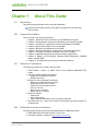

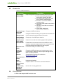
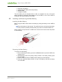


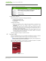


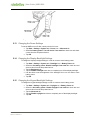
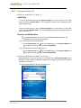
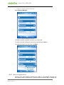


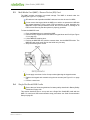
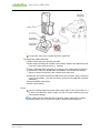
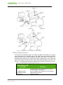
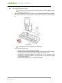
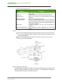
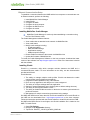
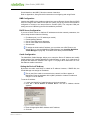
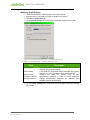
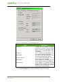
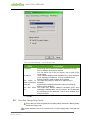
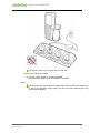
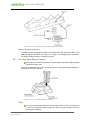


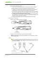

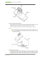
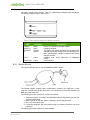

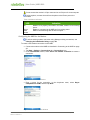
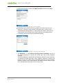
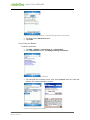


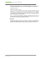


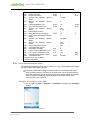
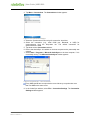

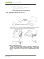

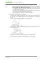

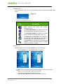
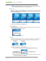
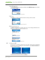
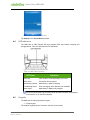

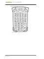

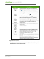
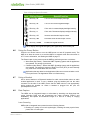


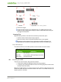

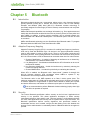
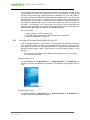

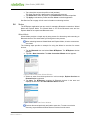
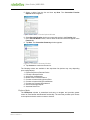
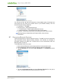


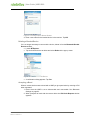
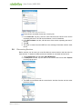
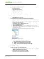
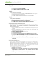
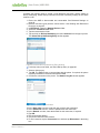


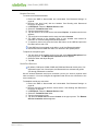
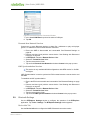
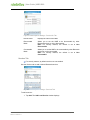
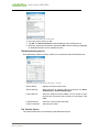


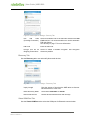


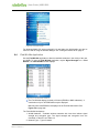
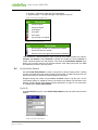


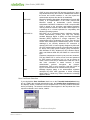
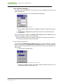
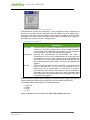

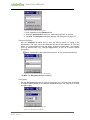

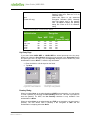
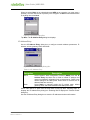

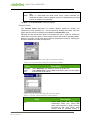

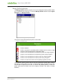

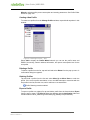
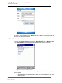
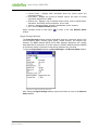
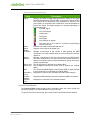
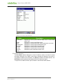
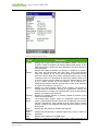

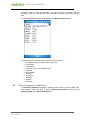
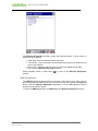
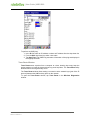
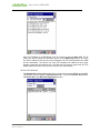


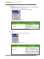
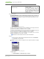

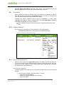


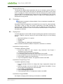
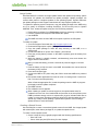


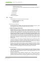
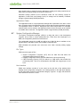
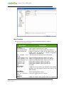
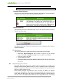
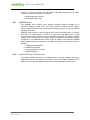

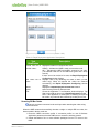
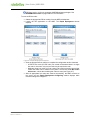

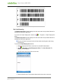
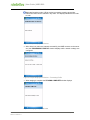
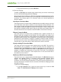


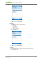
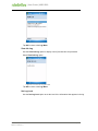


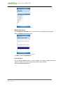


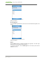

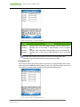

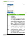
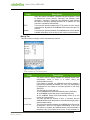
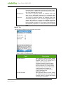


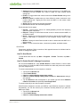
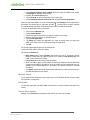

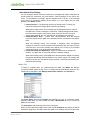
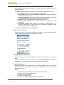
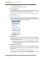

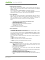
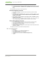


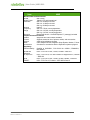
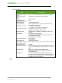
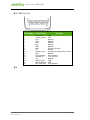
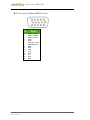
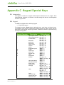


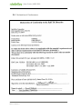


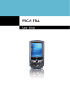

![MC909X User Guide [English] (P/N 72E-72215](http://vs1.manualzilla.com/store/data/006923233_1-b8645820a9c9206bed43f7013f7b5dae-150x150.png)


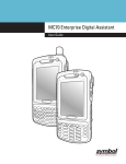
![MC92N0-G User Guide {English] (P/N 72E-162536-02](http://vs1.manualzilla.com/store/data/005752413_1-5c9790f7378b6b81af8236dfa051ab67-150x150.png)