1
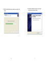
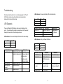
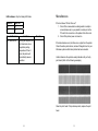
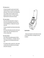
Liability Disclaimer
DESKTOP BARCODE PRINTER
MJ-2844
User’s Manual
Alacrity barcode technology takes steps to assure that the company’s published
engineering specifications and manuals are correct; however, errors do occur.
Alacrity barcode technology reserves the right to correct any such errors and
disclaims any resulting liability. In no event shall Alacrity barcode technology or
anyone else involved in the creation, production, or delivery of the
accompanying product (including hardware and software) be liable for any
damages whatsoever (including, without limitation, damages for loss of business
profits, business interruption, loss of business information, or other pecuniary
loss) arising out of the use of or the results of use of or inability to use such
product, even if Alacrity barcode technology has been advised of the possibility of
such damages.
CAUTION:
Any changes or modifications not expressly approved by the party responsible
for compliance could void the user's authority to operate the equipment.
Product Improvements
Continuous improvement of products is a policy of Alacrity barcode technology All
specifications and signs are subject to change without notice.
I
Table of Contents
Getting Started ..................................................................3
Package Contents.................................................................... 4
Connecting the Power Supply ................................................. 5
Getting to Know Your Printer ...........................................6
Parts and Features ...................................................................6
Controls and Indicators ........................................................... 9
Loading Ribbon and Media ............................................11
Loading Ribbon .................................................................... 11
Loading Media...................................................................... 16
Calibration and Configuration........................................20
Performing Calibration and Configuration ............................ 20
Resetting to Factory Default Settings .................................... 21
Installing the Printer Driver ............................................22
Troubleshooting ..............................................................32
LED Diagnosis ..................................................................... 32
Miscellaneous ....................................................................... 35
Recovery .............................................................................. 36
Caring for Your Printer....................................................37
Cleaning ............................................................................... 37
Media Sensor ........................................................................ 37
Thermal Print Head ............................................................... 37
Replacing the Thermal Print Head ......................................... 40
Important notice during TPH replacement ................... 42
Technical Reference ....................................................... 43
2
Getting Started
Congratulations on choosing the Alacrity desktop barcode printers.
This manual will help you get to know your new printer.
There are two parts to this manual,an operation guide information.
The operation guide is illustrated to help you quickly become familiar
with the printer.
The related information includes troubleshooting, maintenance
and technical information for your reference.
3
Package Contents
Connecting the Power Supply
Connect the power supply as below.
WARNING! Do not operate the printer and power supply in an
area where they can get wet.
Printer
Power Supply
Power Cord
CD ROM
USB Cable
Media Holder
Make sure the power switch is in the "O" position.
1. Insert the barrel connector of the power supply into the power
jack on the back of the printer. Note the location of the power
jack for different models in the diagrams below.
2. Insert the separate power cord into the power supply.
3. Plug the other end of the cord into an AC electrical outlet.
Note:Pictures for reference only!
4
5
Getting to Know Your Printer
The illustrations that follow describe the printer’s parts, features,
controls, and indicators.
Parts and Features
Ribbon Pick-up Holder
Top Cover
Media Hanger
H Cover
Power Switch
Power Indicator
Release Levers
Ready Indicator
Feed Button
6
7
Controls and Indicators
Ribbon Supply Holder
Thermal Print head
The printer’s controls and indicators are shown in the diagram
below. The following table explains control and indicator
functions.
Platen Roller
Top Cover
Power Switch
Power Indicator
Power Switch
Ready Indicator
Feed Button
8
9
Loading Ribbon and Media
Control /
Indicator
Function
This section describes how to load ribbon and media in printer.
On: turns on normal operation
Power Switch
Off: turns off power
Note: Turn power off before connecting or
disconnecting cables
Loading Ribbon
Note: This section does not apply to direct thermal printing.
Green light shows the power-on
Power Indicator
Light off shows the power-off
Blinking light indicates error has occurred
Green shows printer is ready to operate
Ready Indicator
1. Lift the top cover to expose the media compartment.
2. Unlatch the print head module by pushing the two white
release levers on the sides toward the rear.
3. Turn over the print head module to expose the ribbon
supply holder.
Blinking light indicates printer is paused or
data transferring
Seagull driver status monitor
Press to advance labels to the first printing
position
Feed Button
Press to take the printer out of "pause"
Press and hold while turning on the power
to print out a configuration profile
10
11
Media Compartment
Print Head Module
Release Lever
Release Lever
4. Unwrap the ribbon roll pack and separate the ribbon roll
and the bare core.
5. Attach the edge of the ribbon on the bare core and wind it
a little bit onto the core.
6. Insert the ribbon roll into the supply holder. (First snap in
the left side and then the right side.)
Ribbon Supply Holder
Ribbon Supply Holder
Ribbon Roll
Bare Core
12
13
7. Turn back the print head module and then insert the bare
core into the pick-up holder. (First snap in the left side, and
then the right side.)
8. Turn the wheel of the print head module to ensure the
ribbon is tightly wound.
9. Press down the print head module firmly until you hear a
snap.
Wheel
Ribbon Pick-up Holder
Bare Core
Print Head Module
14
15
2. Remove the media hanger.
Loading Media
1. Lift the top cover to expose the media compartment.
Media Compartment
Media Hanger
3. Load the media roll onto the hanger from left to right.
Media Roll
Media Hanger
16
17
4. Click the media hanger back into the media
compartment.
5. Align the media roll to the left end.
6. Move the shield from right to left until it leans against the
media.
7. Unlatch the print head module.
8. Hold the print head module upright with one hand to
allow the media to pass under it. Lead the media through
the media guides with the other hand.
9. Lead the media over the platen roller.
Media Compartment
Print Head Module
Media Guides
Media Roll
Shield
18
10. Put the print head module down and press down firmly
until you hear a snap.
11. Close the top cover and turn on the printer or press the
"FEED" button if the printer is already on.
19
Calibration and Configuration
This section discusses calibration, printing configuration and
resetting the printer to factory defaults.
Performing Calibration and Configuration
1.
2.
3.
4.
5.
Turn off the printer power.
Press and hold the feed button while turning on the power,
until the printing motor is activated.
Calibration is performed while the printer automatically feeds
the label stock for a certain length, the printing motor
suspends for one second and then prints out a configuration
profile.
The profile includes firmware version, ROM checksum,
RS-232, thermal transfer/direct thermal settings, hardware
configuration, and font types.
At PPLB emulation, the printer enters character dump mode.
To exit from dump mode, press the feed button again. (If you
accidentally print the label without exiting from dump mode in
advance, you need to turn on the printer or press feed button
again to print normally.)
Resetting to Factory Default Settings
1. Turn on the printer and wait for 5 or more seconds.
2. Press the "Feed" button for 10 seconds, and the "Ready"
indicator and "Power" indicator will go off in order.
3. When the two indicators relight, release the feed button.
4. The printer feeds approximately 3 ~5 blank labels, and
then resets to the factory defaults.
Note: Revise the factory default settings that stored in flash,
even if turn off the power source cannot be eliminated.
Important!
You must always carry out calibration when
changing media. Failure to do so will result in improper
detection by the label sensor.
20
21
Installing the Printer Driver
1. Turn off the printer. Plug the power cable into the power
socket on the wall, and then connect the other end of the
cable to printer's power socket. Connect the USB cable
to the proper port on the printer and on your computer.
4. Assign the directory to keep driver, (for example:C:\Seagull)
and click "Next".
2. Prepare the documentation and software CD-Rom from
printer package and then install to CD-Rom drive of your
computer.
3. Select “I accept…”and click "Next ".
22
23
5. Click "Finish".
6. Select Install printer drivers and Click "Next"
24
25
7. Select model & emulation - the following examples are based
on model OS-214 plus PPLA
8. Select the port of the printer and click "Next".
Argox OS-2140 PPLA
A rgox OS-2140 PPLA
A rgox OS-214 plus PPLA
A rgox OS-2140 PPLA
26
27
9 . Enter Printer name (i.e. Argox OS-214 plus PPLA) and select
"do not share this printer”, and click "Next".
Argox OS-214 plus PPLA
Argox OS-2140 PPLA
10. Check all the data on the showing screen, if it is correct, click
"Finish".
Argox OS-214 plus PPLA
USB001
Argox OS-214 plus PPLA
7.1.9_M-5
28
29
11. After the related files have been copied to your system, click
"Finish".
12. After driver installation is complete, click "Close".
The driver should now be installed.
Installed printer Argox OS-214 plus PPLA
Installing printer ‘Argox OS-214 plus PPLA’…
30
31
Troubleshooting
Normally, when the printer is in not working properly, the "Power"
LED blinks continuously; while printing and communication
between the host and printer stops.
LED Diagnosis
Power and Ready LEDs blinking continuously indicates printer
errors. To understand the problem, please observe the Power and
Ready LEDs and refer to the following solutions:
LED Indicators: Power and Ready LEDs blink alternately
Power LED
ON
OFF
Ready LED
OFF
ON
Possible Problems
Solutions
Ribbon out
Supply the ribbon roll
Ribbon jam
Recover the jam
Ribbon sensor error Replace ribbon sensor
Remarks
Not applicable to
direct thermal
type.
LED Indicators: Power and Ready LEDs blink at the same tempo
LED Indicators: Only the Power LED blinks
Power LED
ON
OFF
Ready LED
ON
OFF
Power LED Ready LED
ON
ON
OFF
ON
Possible Problems
Solutions
Remarks
If you use a
Miss-detect gap
Check the label path
Check the label sensor continuous label roll
and run under
Windows, select
continuous media.
Label stock out
Supply the label roll
Label stock not
Install the label roll
installed
Label jam
Recover the jam
32
Possible Problems
Solutions
Serial IO error
Check the baud rate
Memory full
Add the extension
RAM(flash memory
card)
Cutter failed, or jam Check the cutter
at cutter
Recover the jam
Hardware error
Call for service
33
Remarks
Serial interface only
Occurs only when
installing or setting the
cutter
LED Indicators: Only the Ready LED blinks
Miscellaneous
Power LED
Ready LED
ON
ON
ON
OFF
If the host shows "Printer Time out"
1. Check if the communication cable (parallel or serial) is
connected securely to your parallel or serial port on the
PC and to the connector on the printer at the other end.
2. Check if the printer power is turned on.
Possible Problems
Solutions
Print head too hot
Printing will stop until the
print head cools to an
acceptable printing
temperature. When it
does, the printer will
automatically resume
operation.
Remarks
If the data has been sent, but there is no output from the printer.
Check the active printer driver, and see if Seagull driver for your
Windows system and the label printer has been selected.
Vertical streaks in the printout usually indicate a dirty or faulty
print head. (Refer to the following examples.)
Clean the print head. If the problem persists, replace the print
head.
34
35
Poor printout quality:
The ribbon may not be qualified.
The media may not be qualified.
Adjust the Darkness (heat temperature).
Slow down the print speed.
Refer to the next chapter and clean the related spare
parts.
Caring for Your Printer
Adhesives and coatings of media can over time transfer onto the
printer components along the media path including the thermal
print head and media sensor. This build-up can accumulate dust
and debris. Failure to clean the print head, media path, and media
sensor could result in inadvertent loss off labels, label jams and
possible damage to the printer.
Recovery
Note: Turn off the printer before cleaning.
After correcting problems, simply press the panel button or restart
the printer to continue your print jobs. Make sure the LEDs are not
blinking and remember to resend your files.
Cleaning
Clean the following components of the printer using a cotton bud
dampened with alcohol. Do not soak the cotton bud excessively.
Media Sensor
Debris or dirt on the paper sensor can cause a miss-read or
unstable detection of the label gap. Clean with a cotton bud
dampened with alcohol.
Thermal Print Head
Thermal paper stock and the ribbon release debris on the print
head, which degrades printing quality. Clean the print head with
methanol or isopropyl alcohol and a cotton bud. Do not touch the
heater element with your fingers. Debris or dirt on the roller should
be cleaned with alcohol.
36
37
TPH Cleaning Interval:
It’s strongly recommended to regularly clean print heads at
least when changing every one ribbon roll (in thermal transfer
printing mode), or every one label roll (in direct thermal printing
mode). In addition, if printers are operated under critical
applications and environments, or it’s found print quality is
degraded, please clean print heads more frequently.
TPH Cleaning Material:
Surface of print head’s heating element is very fragile. To
prevent from any possible damage, please use soft cloth or
cotton buds with “Ethanol” or “industry alcohol” to clean print
head surface.
It’s strongly recommended to wear hand gloves during cleaning
progress.
Do not touch print head surface by bare hands or with any hard
equipment. Water or spit should be kept away in case of
corrosion on heating elements.
TPH Cleaning Direction:
When cleaning print head, please always wipe in One-Way
Direction - from Left to Right only, or, from Right to Left only, to
clean “Heating Line” of print head gently without excessive
stress.
Do not wipe back and forth, to avoid dust, dirt, or ribbon residue
on cleaning cotton would be attached onto print head again.
(Please refer to below picture)
38
Special Caution:
Warranty of print heads will be void if print head serial number
is removed, altered, defected, or made illegible, under every
circumstance.
39
Replacing the Thermal Print Head
1.
2.
3.
4.
Switch off the power and wait for both LEDs to go off.
Unlatch the print head module.
Remove the ribbon.
Push the print head firmly into the casing and shift it to the
left. It will release from the module.
6. Disassemble the print head and the mounting bracket by
releasing screws.
7. Replace with a new print head. Reassemble the print head
module in reverse order. Be careful not to touch the print
head elements.
5. Disconnect the print head cable.
40
41
Important notice during TPH replacement
1. Heater line should NOT be touched by bare hands to
prevent any damage caused by ESD or corrosion.
2. Surface of heaters should NOT be hit or scratched by
sharp or hard things to prevent any damage by scratch.
3. Residue or contamination should NOT be removed by a
cutter to prevent any damage by dent or scratch.
4. Connector side should NOT be touched when cleaning
TPH to prevent delaminated solder between FPC and
wafer. Ink-jet characters could be erased, if cleaning cloth
was touched them on FPC or label.
5. Heater surface should be free from any condensation.
6. TPH should NOT be put heater surface down.
Technical Reference
General Specifications
Specification
Printing method
Printing
resolution
Printing speed
Printing length
Printing width
Memory
CPU type
Media sensor
Operation
interface
Communication
Interface
Fonts
42
Direct Transfer/Thermal Transfer
203 dpi (8dots/mm)
2~3ips(51~76mm/s)
Max 43”(1092mm)
Max 4.16” (105mm)
8MB DRAM(6MB user available)
4MB Flash ROM(2MB user available)
32 bit RISC microprocessor
Reflective x 1
LED indicator(Power/Ready)x2, Button(Feed)x1
Centronics Parallel, USB(2.0)
Internal character sets standard 5 alpha-numeric fonts from
0.049”H ~ 0.23” H (1.25mm ~ 6.0mm)
Internal fonts are expandable up to 24x24 4 direction 0 ~ 270
rotation Soft fonts are downloadable
43
Barcodes
1D:Code 39, Code 93,Code 128/subset A/B/C, Codabar,
Interleaved 2 of 5, UPC A/E/2/5 add-on, EAN-13/8, UCC/EAN
128, Postnet, Plessey, Interleaved 2 of 5, Interleaved 2 of 5 with
a modulo 10 checksum, Interleaved 2 of 5 with a modulo 10
checksum and shipping bearer bars , Code 128, UCC/EAN
Code 128 Random Weight, HBIC, Telepen , FIM
2D:PDF-417, MaxiCode, Data Matrix (ECC200 only) ,QR
Code, Composite codes
Graphic
Software-Label
editing
Software-Utility
Media Type
Media
Ribbon
Dimensions
Weight
Power Source
Operation
Environment
PCX, BMP, IMG, HEX ,GDI
Windows Driver (Win 2003/XP/Vista/Windows 7) BarTender ,
Printer Utility, Font Utility
Roll-feed, die-cut, continuous, fan-fold, tags, ticket in thermal
paper or plain paper and fabric label
Max Width:4.33”(110mm) Min Width:1”(25.4mm)
Thickness:0.0025”~0.01”(0.0635~0.254mm)
Max roll capacity(OD):4.3”(109mm)
Core size:0.5”(12.7mm) (1”(25.4mm) optional)
Ribbon Width: 1”~4”
Ribbon roll – max OD: 1.45”(37mm)
Ribbon Length: max 92m
Core size – ID: 0.5”(13mm) with notch
Wax, Wax/Resin, Resin (Outside Ribbon)
W 182mm x H 161mm x L 280mm
2.0kgs
Universal Switching Power Supply Input: 100V~240V,
1.5A, 50~60Hz, Output: 24VDC, 2.4A
Operation Temperature: 40°F~100°F (4°C~38°C), 10% ~ 90%
non-condensing,
Storage Temperature: -4°F~122°F (-20°C~50°C)
44
45