1
T L Audio
User Manual
EQ2 VALVE EQUALISER
Tony Larking Professional Sales Limited, Letchworth, England.
Tel 01462 490600, Fax 01462 490700.
INTRODUCTION
The T L Audio EQ2 Parametric Valve Equaliser combines classic valve techniques
with low noise solid state circuitry to produce a unit offering sweepable high and low
pass filters plus four bands of fully variable equalisation on each of its two channels.
Both channels feature a line level input, plus a mic input with switchable 48V
phantom powering. Further flexibility is provided from a front panel auxiliary input
and stereo operation mode. Typical applications include direct recording to tape,
instrument preamplifier, use as outboard EQ during mixdown, and as a main stereo
equaliser for monitoring and PA systems.
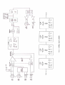
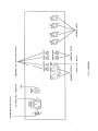
The block diagram of one of the channels is shown in fig.1. A solid state,
electronically balanced input amplifier is used, to achieve state of the art performance
with very low noise, low distortion and wide bandwidth. Two XLR input sockets are
provided per channel, for mic and line inputs. The mic input is suitable for low
impedance (150-600 ohm) microphones, with a gain control range of +16 to +60dB. A
front panel switch provides 48V phantom power to both channels. The line input has
an effective overall gain range of -10 to +35dB, allowing the valve stages to be fully
driven from line level signals in the range -20 to +20dBu.
A front panel mounted auxiliary jack socket allows direct access to the channel inputs.
The input is suitable for a variety of sources, including guitar, acoustic pickup and
keyboard.
The input section also provides continuously variable, individually switchable, high
and low pass filters to tailor the frequency response to eliminate unwanted LF or HF
noise from the input source.
An insertion point is provided immediately after the input stage, to allow a compressor
or other processor to be used as required. The insertion point is unbalanced, at a
nominal operating level of -2dBu.
Both channels feature a four band parametric equaliser. Each band is individually
switched in or out of circuit, and an overall EQ in switch is provided. All of the EQ
bands comprise centre-detented cut or boost control, swept frequency and
continuously variable Q controls. A total of six twin triode valves are employed in the
EQ2: one valve stage per EQ band, plus a two stage post EQ driver circuit.
Master level controls are provided, post EQ. These controls are also centre-detented
for ease of line-up, but may be varied in conjunction with the input gain controls to
alter the operating level through the valve circuitry, to introduce as much (or as little)
of the characteristic valve sound as required. Variable intensity peak LEDs glow to
indicate the degree of valve drive attained.
The Stereo mode switch is a powerful facility, enabling precise tracking of
equalisation between channels, with quick adjustment and no need to match settings
on two sets of controls. All of the EQ controls are ganged; i.e. Cut/Boost, Frequency,
Q and band in/out switching. The input and output gain controls, high and low pass
filters and overall EQ in/out switches retain individual channel operation for
maximum flexibility.
A solid state, electronically balanced output stage with outputs switchable for +4dBu
or -10dBu nominal output level completes the channel. The balanced signals are
terminated on metal XLR sockets, with unbalanced line level inputs and outputs
provided on 0.25” jack sockets.
Please read this manual fully before installing or operating the Equaliser.
PRECAUTIONS
The T L Audio EQ2 Parametric Valve Equaliser requires very little installation, but
like all electrical equipment, care must be taken to ensure reliable, safe operation. The
following points should always be observed:
- All mains wiring should be installed and checked by a qualified
electrician,
- Ensure the correct operating voltage is selected on the rear panel
before connecting to the mains supply,
- Never operate the unit with any cover removed,
- Do not expose to rain or moisture, as this may present an electric
shock hazard,
- Replace the fuse with the correct type and rating only.
Warning: This equipment must be earthed.
INSTALLATION
AC Mains Supply.
The equaliser is fitted with an internationally approved 3 pin IEC connector. A
mating socket with power cord and mains plug is supplied. All mains wiring should be
performed by a qualified electrician with all power switched off, and the earth
connection must be used.
Please note that when using this unit with alternate supply voltages (in foreign
countries, for example) the position of the voltage selector switch on the rear of the
unit may need adjusting. The unit may be set for 115V (accepting voltages in the
range 110V to 120V, 60Hz AC) or to 230V (for voltages in the range 220V to 240V,
50Hz AC). The setting may be adjusted by inserting a small flat bladed screwdriver
into the slot of the switch, and sliding the switch to the left (for 115V) or to the right
(for 230V).
Alternate supply voltages may also require a different power cable or mains plug. If in
doubt, consult local electrical regulations.
Warning:
attempted operation on the wrong voltage setting, or with an
incorrect fuse, will invalidate the warranty.
Audio Inputs.
Each channel has two female, 3 pin XLR connectors, for mic and line sources. Both
are compatible with either balanced or unbalanced signals, when the mating
connectors are appropriately wired:
Balanced inputs:
- Pin 1 = Ground (screen).
- Pin 2 = Signal Phase (“+” or “hot”).
- Pin 3 = Signal Non-Phase (“-” or “cold”).
Unbalanced inputs:
- Pin 1 = Ground (screen)
- Pin 2 = Signal Phase (“+” or “hot”).
- Pin 3 = Signal Ground.
When using unbalanced signals, the signal ground may be obtained by linking pins 1
and 3 in the mating XLR connector. Good quality screened cable should be used,
particularly for microphone or low level sources, to prevent hum or noise pickup.
Unbalanced Line Inputs.
An unbalanced line level input is provided for each channel, on a 0.25” mono jack
socket. The mating plugs should be wired as follows:
- Tip =
Signal Phase (“+” or “hot”).
- Screen = Ground.
Auxiliary Inputs.
A 2 pin (mono) jack plug is required, which should be wired as follows:
- Tip =
Signal Phase (“+” or “hot”).
- Screen = Ground.
Insertion Points.
The insertion points are interfaced via a 3 pin, 0.25” switched jack socket on the rear
of the unit. The pin connections are:
- Sleeve = Ground,
- Tip = Send,
- Ring = Return.
The insertion point is unbalanced, and operates at a nominal level of -2dBu . If used
as an additional send only (e.g. as a send to a tape machine or monitor mixing desk),
the Tip and Ring should be wired together, to preserve the signal path through the
insertion point.
Outputs.
The outputs are via balanced, 3 pin male XLR connectors. The mating connectors
should be wired as follows:
- Pin 1 = Ground (screen),
- Pin 2 = Signal Phase (“+” or “hot”),
- Pin 3 = Signal Non-Phase (“-” or “cold”).
If an unbalanced output is required, pins 1 and 3 should both be connected to ground.
Nominal Output Level.
A switch on the rear panel allows the output to be matched to equipment at a nominal
operating level of +4dBu or -10dBu. Most professional equipment requires +4dBu
(approximately 1.2V rms), but some small mixing consoles, portable tape recorders
or domestic audio equipment require -10dBu (approximately 225mV rms). The
switch should be set to the position which results in the best signal to noise ratio,
whilst preserving sufficient headroom.
Unbalanced Outputs.
An unbalanced line output is provided for each channel, on a 0.25” mono jack socket.
- Tip =
Signal Phase (“+” or “hot”).
- Screen = Ground.
Ventilation.
The unit generates a small amount of heat internally, mainly due to the valve heaters.
This heat should be allowed to dissipate by convection through the grill in the front
panel, which must not be obstructed. Do not locate the EQ unit where it will be
subject to external heating, for example, in the hot air flow from a power amplifier or
on a radiator.
The EQ may be free standing, or mounted in a standard 19” rack.
Rear Panel.
The rear panel connectors are identified in fig.2.
OPERATION.
Front Panel.
The front panel controls are identified in fig.3
Input Stage.
Ensure that the correct input connector, mic or line, is being used and that the front
panel switch is set to the appropriate position. Note that both mic and line inputs may
be connected at the same time, but only one is selected.
+48V phantom power is available at the mic socket, selected by a front switch and
signalled by a red LED. Phantom power should only be used in conjunction with
suitable microphones.
CAUTION: Operation of the phantom power switch, or plugging a microphone in
with phantom power applied, may cause a click or thump in your loudspeakers. To
prevent this happening, ensure that the system gain is set to minimum (e.g. on your
mixing console fader or power amplifier), before operating the switch or plugging in a
microphone.
If the gain required is not known, set the control to minimum with the EQ by-passed,
and gradually increase the gain until the required output level is achieved. Unity gain
(0dB) is obtained from the line input at the centre-detent of the gain control.
Auxiliary Input.
The front panel auxiliary input socket accepts signals from guitar, keyboard, and high
impedance pickups or microphones. Plugging a jack plug into the auxiliary socket
automatically disconnects the channel mic or line inputs, and replaces them with the
aux input.
The sensitivity of the Aux input is controlled by the mic/line switch. In the line
position, low gain is selected, suitable for most keyboards or active guitars, whilst in
the mic position, the gain is increased to match passive guitars and hi-z microphones
or pickups. The input gain control also remains operative when using the Aux input.
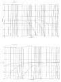
HF and LF Cut Filters.
Both channels are equipped with high pass (also known as LF cut) and low pass (or
HF cut) filters, with a slope of 12dB per octave. Each filter has a continuously
variable frequency control and on/off switch with yellow LED.
The filters have a cut-only response,to tailor the roll-off of the frequency response,for
example to' remove unwanted low frequency rumble or hum, or excessive high
frequency noise or hiss, which may be present on the input signal. Typical response
curves are shown in the specification section of this manual,
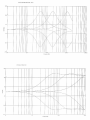
Equalisation.
Before switching the EQ into circuit, it is advisableto set the cut/boost controls to their
centre, or flat, position. The EQ is brought into circuit with the overall "EQ-IN' push
switch, signalled by a green LED. Each band also has an individual select switch and
associatedLED.
Both channelsfeature four bands of equalisation, all with fully variable cut and boost
controls offering +/-15dB of range, swept frequency and variable Q. (The "Q" of the
filter is a measureof the shapeof the frequency responsecurve, and is closely related to
the bandwidth, or range of frequencies, controlled by the filter). High Q settings (about
5 at the maximum setting on the EQ2) result in sharp, narrow bandwidths generally
used for audio correction or effects. Intermediate settings, say 1 to 3, are generally
used to enhance or reduce a broader range of frequencies, typically to make an
instrument or vocal "stand out", or recede, into the mix. Finally, low Q values (down to
about 0.5 on the EQ2) provide more gentle contouring, or "sweetening" of the
response.
The four bands ofEQ per channel are nominally designatedas LF (low frequency), LM
and HM (low and high mid frequency) and HF (high frequency). However, the
frequency variation available on each band allows overlapping of two, or more, bands
into the samefrequency range. This arrangementaffords maximum flexibility, allowing
for example, reduction of a narrow band whilst simultaneouslyboosting an overlapping
broader band of frequencies. The LM and HM bands have a peaking response,whilst
the LF and HF bands are switchable to peaking or shelving response.Used individually
or in combination the filter bands allow comprehensiveequalisation of any audio signal,
with the unique character of valve circuitry.
Typical response curves and the effect of control setting variations are shown in the
specification section of this manual. Note the wide, 40KHz bandwidth of the EQ2.
Stereo Switch.
Most two channel equalisers require the time consuming and inaccurate practice of
attempting to match settings on two sets of controls. The EQ2 provides a simple and
quick meansof ganging the controls into a full stereo equaliser.
Operation of the Stereo switch, signalled by a yellow LED, causes the channel A
(lower) set of equaliser controls to operate on both channels. Thus the cut/boost
lu~wd!nb~ ~U!A'\°nOJ
~q:l. qo:l.'ew 0:1.I~A~I :l.nd:l.no ~q:l. ~U!nOJ:l.UOO:l.SI~M 'I~A~I l'eu3'!S q~~ :I.'e:l.O~JJ~U~A!lpJ~AO UB
0:1.J~:l.O'eIBqO~AfBA ~pU~~ q~noJq:l. 'punos
UB~IO 'e JOJ I~A~I MOl 'e :I.'eS~~'e:l.SUO!:I.'es!fBnb~
~q:l. ~A!lP 0:1.10J:l.UOO
U!'e~ :l.ndu! ~q:l. ~U!:l.snfp'e Aq P~U!'e:l.qo~q A'eW :l.O~JJ~p~J!S~P ~q:l. snql.
'AJ:I.!nOJ!O~AfBA ~q:l. J~:jJB P~:I.'eOOIS! 'IOJ:l.UOOU!'e~ :l.nd:l.no JO 'I~A~I J~:l.S'eW:l.nd:l.no ~ql.
1tJAtJ'} :JRd:JRO JtJ:JSBW
'UO!:jjO:l.S!PP~:I.'eI~J~U!dd!IO qSIBq :l.OUpUB ':I.u~wd!nb~ ~AreA JO O!:l.S!l~:l.O'eIBqO
S!
qO~M UO!:jjO:l.S!P°!U°WIBq U~A~ ApUBU!W°p~Jd S! S~:I. '~SJnOOJO 'UO!:jjO:l.S!PU! ~S'e~J°U!
(S~W!:I.£ AI~:I.'eW!X°Jdd'e) gPOI 'e U! S:l.lnS~JI~A~I ~U!:I.'eJ~dOU! ~S'e~J°U! gpOI 'e 'q:l.P!MpUBq
O!pn'e ~q:l. J~AO :l.UB:l.SUOO
AlfBn:jj!A ~noq:l.IV
'ngpo
I~A~I 8U!:I.'eJ~dOUB 0:1.dn MOl ApU~:l.S!SUOO
~IB zoa
:l.noq'eJO S~~'e:l.SJ~S!fBnb~ ~q:l. ~noJq:l.
~q:l.JO SO!:l.S!l~:l.O'eIBqO
UO!:jjO:l.S!P~ql.
'~U1UrnW~J
WOOJp'e~q JO gpZ A~p'ewrxOJdd'e S! ~J~q:l. U~qM s~:I.'eu!Wnn! aa'l :>J'e~dp~J ~ql. 'J~pIBq
U~A!lP ~IB S~AfBA ~q:l. S'e 'ngp91 + 0:1.17+ ~~UBJ ~q:l.J~AO AJ;!SU~:l.U!
U! ~U!S'e~J~U!~S~AfBA~q:l.
Aq P~:I.'eJ~U~~~U!~q :l.U~:l.UO~
~!U°WIBq U~A~ JO "~U!WIBM.,, ~q:l.JO :l.U~P'~ ~q:l.JO UO!:I.'e~!pU!
pOO~ 'e S~A!~ aa'l
~A!lP J~qUIB ~q:l. ':l.u!od S~:I. :l.V '~~'e:l.S ~A!lP ~AreA oa
J~:jJB AI~:I.'e!P~WW! 'uO!:l.O~Soa
:l.sod ~q:l.
~q:l.JO :l.nd:l.no ~q:l. :I.'eI~A~I fBU~!S ~q:l. ~:I.'eO!PU!saa'l
~ql.
.SU~,} ')fBtJd pUB tJA!JU
'~:I.'eJ'ed~sU!'eW~J OSI'eSIOJ:l.UO~J~:l.IY pUB SU!'e~ :l.nd:l.no pUB :l.ndU! ~ql. 'P~!ldd'e ~U!~q
UO!:I.'eS!IRnb~~q:l.JO :l.O~JJ~~q:l. ~U!JRdwo~ U! A:I.!I!q!X~IJ wnW!XRW JOJ '~:l.RIBd~s S~qO:l.!MS
NI-oa
nRJ~AO ~q:l. S~A'e~1 :l.nq 'q~:I.!M.SJJOfUO pURq ~l(:I. s~pnl~U! ~U!~UR~ O~J~:l.S~l(l.
'sq:l.'edfBu3'!S q:l.oq 0:1.UOWWOO
AI~:I.'e!P~WW!~IB 'S~U!~S
10J:l.UOO0 pUB Aou~nb~lJ ~q:l. q:l.!M. ~UOfB 'pUBq qOR~JO 8u!n~s
.
EQ2 Parametric Equaliser Technical Specification.
Inputs: Line level balanced@ +4dBu nominal, via XLR sockets,plus unbalancedon jack sockets.
Maximum input +24dBu,input impedancegreaterthan 5Kohm.
Instrumentinput on front paneljack, switchableto high/low gain for guitar or keyboard.
Maximum input level +22dBu. Input impedance220Kohm.
Mic input balancedon XLR, with switchablephantompower.EIN -127dBu(150 ohms,
22Hz-22KHz).
Input gain range+ 16dBto +60dB (Mic), -22dB to +22dB (Line).
Filters: Continuouslyvariable, individually switchedhigh and low passfilters, 12dBper octave.
LF cut frequencyrange 30Hzto 1KHz, HF cut frequencyrange 1KHzto 25KHz.
Equalisation:
Four bandsper channel,individually switched,plus overall EQ ON switch.
Each channelfully parametric,with continuouslyvariable cut/boost,frequencyand Q.
LM and HM bandspeaking, LF and HF bandsswitchableto shelvingor peakingresponse.
Cut and boost:+/-15dB.
Frequencyrange,LF and LM:
30Hzto 3KHz.
Frequencyrange,HM and HF:
1KHz to 20KHz.
Q range0.5 to 5.
Stereo Operation:
Full stereoganging of all EQ controls,i.e. cut/boost,frequency,Q controlsand in/out buttons.
Overall EQ IN buttons,filters, input gain and output gain remain seperate.
Drive and Peak LEDs:
Variable intensity drive LEDs, start to glow at thresholdof valve compression.
PeakLEDs indicate approximately2dB of headroomremaining.
Monitor point is the EQ output,prior to masterlevel control.
';)':)~ou }no~~
;)~u~':)
o} }':);)fqns ;)J~ suo~~':)m':)~
.
-
;)Aoq~ ;)U
'V A~£
@ AOa JO A~I I
:S}U3W3.1!nb3.1
'~;)P
(.,01)
UIUlO~'l
'p;)}unow
.l3MOd
){,:)~J 11£
:SOO!SU3W!U
'gpOOI ~
J;)}~tB ;)~~J ':)~Aa
'P;)J;)}U;)':)
SIOIJUO':)
p~ U! 03 'ZH)IZZ-ZHZZ 'I:)~I ~u!Ul°u ngpt+ J:)J 'Jgp08-
'uno SJ~ijY l~U P~ U! oro
:3S!ON
'gp'l- '0+ :ZH)IOt O}ZHOI
:3Soods3.1A303nb3.l.!l
l;)UU~':) J~ J;)A!lp }nd.}no
;)~mSOft\t~ SRld'J~IY 03 J~ ;)~~S ~A~A ;)UOs~ ~~u~Jrn 's:)PO!J:)
~
LXV'lI/£8J;)3: X!S
:S3AIWA
'(P;)':)u~~q)ngp9'l+ I~~I wnw~
1~~1
Itrn!Ul°U ngpOI- JOngpt+ O} ~lq~q':)}!/I:\S
I;)u~d J~J 'S};)){':)Os
){':)~f~:)U~I~qun snld S"lIlX P;)':)u~l~g
:s}nd}no
':)~U~Jgp SI-/+
)
:1°.l}ooJ 13A3'J.l3}S~
I
~ :;;
SERVICE
Should the equaliser require service, it must be taken or posted to an authorised dealer
with a description of the fault. Please retain the original packing for possible future
use, and ensure the unit is suitably protected during transit. The manufacturer cannot
accept responsibility for damage caused during transportation.
The equaliser is supported by a limited warranty for a period of one year from the date
of purchase. During this period, any faults due to defective materials or workmanship
will be repaired free of charge. The warranty excludes damage caused by deliberate or
accidental misuse, tampering, operation on the incorrect mains voltage, or without the
correct type and value of fuse fitted. It is the user’s responsibility to ensure fitness for
purpose in any particular application. The warranty is limited to the original purchase
price of the equipment, and excludes any consequential damage or loss.
Please record the following details, and retain proof of purchase:
Serial Number.............................
Date purchased...........................
Dealer.........................................
Tony Larking Professional Sales Limited,
Letchworth, England.
Tel: 01462 490600. International +44 1462 490600
Fax: 01462 490700. International +44 1462 490700