1
Secvest
user manual
Contents
English
1. Scope of delivery........................................................................................................ 56
2. General...................................................................................................................
57
2.1 Safety information.................................................................................................57
2.2 Information on user manual.................................................................................... 57
2.3 Warranty.............................................................................................................. 57
2.4 Disposal.............................................................................................................. 57
2.5 Declaration of conformity.......................................................................................
57
3. Installation example.................................................................................................. 58
4. Overview of the system and control panel........................................................................ 59
5. Overview of the numerical keypad.................................................................................. 60
6. Secvest display........................................................................................................... 62
7. Menu navigation and operation..................................................................................... 63
8. Arming and disarming the system.................................................................................. 63
8.1 Arm/disarm keys....................................................................................................63
8.2 Graphical display of arming/disarming on the display.................................................... 64
8.3 Arming/disarming via the quick arm keys.................................................................... 64
8.4 Arming via the user code......................................................................................... 65
8.5 Arming sub-areas.................................................................................................. 66
8.6 Individual sub-areas.............................................................................................. 67
8.7 Internal arming..................................................................................................... 67
8.8 Internal arming via chip key.................................................................................... 68
8.9 Internal arming via remote control............................................................................ 68
8.10 Arming via wireless control panel............................................................................ 68
8.11 Arming via remote control...................................................................................... 69
8.12 Arming via chip key............................................................................................... 69
8.13 Arming via delay times.........................................................................................
70
9. Responding to an alarm.............................................................................................. 71
9.1 Alarm types.......................................................................................................... 71
9.2 Alarm forwarding..................................................................................................
72
9.2.1 Alarm forwarding via telephone......................................................................... 72
9.2.2 Alarm forwarding to a monitoring station............................................................ 73
9.2.3 Alarm forwarding via email.............................................................................. 73
9.2.4 Alarm forwarding via text message..................................................................... 73
9.2.5 Alarm forwarding in the event of a personal or medical emergency........................... 73
10. User menu............................................................................................................... 74
10.1 Editing users....................................................................................................... 76
10.2 Removing users.................................................................................................. 76
10.3 Creating a user "threat code"................................................................................. 76
10.4 Voice memo....................................................................................................... 77
10.5 Hiding zones...................................................................................................... 77
10.6 System configuration............................................................................................ 77
10.7 On/off functions.................................................................................................. 78
10.8 Bell.................................................................................................................. 78
10.9 Voice message.................................................................................................... 78
10.10 Activity monitor................................................................................................. 78
10.11 Display contrast.................................................................................................. 78
Contents
10.12 Backlighting brightness........................................................................................
10.13 LCD backlighting.................................................................................................
10.14 Backlighting for menu keys/backlighting for arm keys/backlighting for number keys..........
10.15 Zone name announcement...................................................................................
10.16 Date & time......................................................................................................
10.17 Remote controls.................................................................................................
10.18 Volume settings.................................................................................................
10.19 Web access.......................................................................................................
10.20 Time schedule active/inactive...............................................................................
10.21 Contacts...........................................................................................................
10.22 Test................................................................................................................
10.23 Walk test.........................................................................................................
10.24 Sirens & sounders..............................................................................................
10.25 Door locks........................................................................................................
10.26 Outputs...........................................................................................................
10.27 Chip key...........................................................................................................
10.28 Remote controls................................................................................................
10.29 Emergency call button........................................................................................
10.30 Telephone call..................................................................................................
10.31 Log book..........................................................................................................
10.32 Info................................................................................................................
10.33 Ethernet..........................................................................................................
10.34 IP address........................................................................................................
10.35 IP subnet mask.................................................................................................
10.36 Gateway IP address............................................................................................
10.37 DNS primary IP address.......................................................................................
10.38 MAC address.....................................................................................................
10.39 IP link status....................................................................................................
11. Advanced system operation .......................................................................................
11.1 Remote control....................................................................................................
11.2 Wireless cylinder ("Secvest key")..............................................................................
11.3 Additional door lock (FU7010/7025E)..........................................................................
11.4 Operation via telephone........................................................................................
12. Operation via web (app/browser)..................................................................................
12.1 Operation via web browser.....................................................................................
12.2 Operation via app................................................................................................
13. Operation via web browser..........................................................................................
13.1 Setting the Secvest IP address.................................................................................
13.2 Overview of the web interface................................................................................
13.3 Arming & disarming.............................................................................................
13.4 Additional web interface options............................................................................
13.5 Configuring Secvest "time schedules".......................................................................
13.6 Datasets............................................................................................................
13.7 Exceptions..........................................................................................................
14. Terms and definitions................................................................................................
78
79
79
79
79
79
80
80
80
81
81
82
82
83
83
83
83
84
84
84
84
85
85
85
85
85
85
85
86
86
86
86
87
88
88
88
89
89
90
91
92
95
97
97
98
54 | 55
Dear Customer,
Thank you for purchasing this SECVEST wireless alarm panel. This device is built with state-of-the-art technology
and complies with current domestic and European regulations.Conformity has been proven, and all related
certifications are available from the manufacturer on request (www.abus.com). To guarantee safe operation,
it is essential that you observe the instructions in this user manual. If you have any questions, please contact
your specialist dealer.
Everything possible has been done to ensure that the content of these instructions is correct. However,
neither the author nor ABUS Security-Center GmbH & Co. KG can be held liable for loss or damage caused by
incorrect or improper installation and operation or failure to observe the safety instructions and warnings.
No liability can be accepted for resulting damage. No part of the product may be changed or modified in
any way. If you do not follow these instructions, your warranty claim becomes invalid. Subject to technical
modifications. © ABUS Security-Center GmbH & Co. KG, 09/2014
We reserve the right to make changes to these instructions without prior notice. This wireless alarm panel
is suitable for use in combination with detectors and sounders for the protection of property such as your
company, home, garage, garden shed, holiday home, etc.
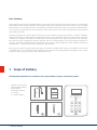
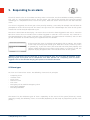
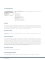
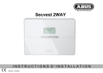
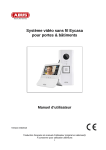
1. Scope of delivery
The following components are included in the scope of delivery for your new Secvest product:
•
•
•
•
Wireless alarm panel
Rechargeable battery
Quick Guide
Mounting material
3 x screws
3 x screw anchors
Quick Guide
Battery
3x
1. Scope of delivery
3x
1
2
3
4
5
6
7
8
9
*
0
#
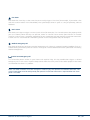
2. General
2.1 Safety information
The alarm panel and its connected components must not under any circumstances come into contact with
water, such as in the bathroom. Use of this product for other than the described purpose may lead to damage
to the product and other dangers such as short circuits, fire, electrical shock, etc. The power supply unit
is suitable for operation on the public electrical grid with 230 V AC/50 Hz. No part of the product may be
changed or modified in any way. Connection to the public electrical grid is subject to your country's specific
regulations. Please seek information on these regulations before connecting the product to the public grid.
Only use the device for the purpose for which it was built and designed. Any other use is not considered to
be the intended use.
2.2 Information on user manual
These instructions contain important installation and operation information. Follow the directions and
instructions in this user guide to ensure safe operation. Store this guide in a safe place for future reference.
This guide constitutes part of the device. If you pass the device on to third parties, please remember to
include this guide.
2.3 Warranty
In the event of a warranty claim, the original receipt with the date of purchase and a short written description
of the problem must be supplied with the product. If you discover a defect on your wireless alarm panel
which existed at the time of purchase, contact your dealer directly within the first two years.
2.4 Disposal
Dispose of the device in accordance with EU Directive 2002/96/EC – WEEE (Waste Electrical and Electronic
Equipment). If you have any questions, please contact the municipal authority responsible for disposal. You
can get information on collection points for waste equipment from your local authority, from local waste
disposal companies or your dealer.
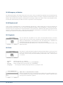
2.5 Declaration of conformity
ABUS Security-Center GmbH & Co. KG hereby declares that the device with item number FUAA50XXX complies
with the essential requirements and other relevant provisions of Directive 1999/5/EC. The declaration
of conformity can be obtained from the following address: ABUS Security-Center GmbH & Co. KG, Linker
Kreuthweg 5, 86444 Affing, Germany.
2. General
56 | 57
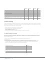
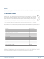
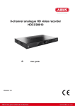
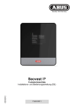
3. Installation example
The following provides a simple installation example to show some important basic applications for the
alarm system. The example focuses on a single-family detached home. A representative installation has been
illustrated here, as an example of how it could be implemented in a similar or more advanced form for your
property as well:
5
7
1
1
7
1
1
1
3
4
4
1
1
2
1
The following components are installed in this example:
1
2
3
4
5
6
7
8 x magnetic contacts at the windows and doors
1 x Secvest key (wireless cylinder) at the doors for easy arming/disarming
1 x Secvest alarm panel
2 x motion detectors indoors
1 x wireless outdoor siren under the roof
1 x wireless control panel in the bedroom
1 x info module in the hallway
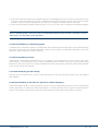
Perimeter protection:Protects against all possibility of access from outside (windows, doors, etc.).An
alarm is triggered as soon as someone gains access to the property.
Interior protection:Predominately used as a second line of defence, armed when the occupants of the
building are away so that the perimeter protection acts as the first alarm and the
interior protection as additional security against intruders.
Internal arming:
If you are in the building you can arm just the detectors for the perimeter protection.
The motion detectors indoors remain disabled in this case.
External arming: All available detectors on the premises are enabled.
An overview of all important terms concerning the alarm panel and alarm system can be found in the
appendix under "Terms and definitions".
3. Installation example
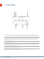
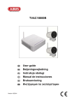
4. Overview of the system and control panel
1
2
8
7
6
3
1
2
3
4
5
6
7
8
9
*
0
#
4
5
1
Graphical display for status, menus and additional information
2
Keys for menu navigation (see "Menu navigation")
3
Quick disarm key for disarming the complete system (code entry required)
4
Loudspeaker/microphone opening
5
Proximity chip key reader area
6
Numerical keypad (see following page)
7
"Internal arm" key for quick arming of perimeter protection
8
Quick arm key for arming the complete system
4. Overview of the system and control panel
58 | 59
5. Overview of the numerical keypad
The numerical keypad is used to enter values in certain menus. Letters and special characters are also stored
on the keypad for entering things like user names or email addresses.
1
2
3
4
5
6
7
8
9
*
0
#
The numerical keypad can be used to input various information. For
example, a name can be entered when creating a new user (see "Users").
The letters are not printed on the numerical keypad in order to provide
a better overview during day-to-day operation. Letters are entered
according to the legend provided below.
In addition to data input, numerical keys 1/3, 4/6, 7/9 and the */#
keys are used for quick arming. If the quick arming function using key
combinations is enabled (ask your specialist installation contractor),
both keys of each key pair must be pressed at the same time. The
following alarm options are available:
1
A, B, C, Æ, Å, Ä,
À, Â, Ç, Ą, Ć, 2
1
2
3
G, H, I, Î, Ï, Ğ, İ, 4
4
5
6
P, Q, R, S, Ś, Ş, 7
7
8
9
*
0
#
T, U, V, Ü, Ù, Û , 8
,():.-!&
@+_*#0
Overview of the numerical keypad
D, E, F, È, É, Ê, Ë, Ę, 3
J, K, L, Ł, 5
M, N, O, Ø, Ö, Ô,
OE, Ń, Ó, Ñ, 6
W, X, Y, Z, Ÿ, Ź, Ż, 9
Fire alarm
Press both fire alarm keys at the same time to manually trigger a fire alarm (for example, if you notice a fire
and wish to warn others in the household). The system beeps twice in cycles as a way of providing acoustic
feedback.
Panic alarm
Press both panic keys to trigger a manual panic alarm (for example, if an intruder enters the property while
you are at home). When the keys are pressed, either an acoustic alarm sounds (tone like for an intruder
alarm) or a silent alarm is triggered, depending on your agreement with the specialist installation contractor.
A silent alarm is transmitted to a monitoring station via the integrated dialler, for example.
Medical emergency call
Press both of these keys to trigger a medical emergency call. If there is a potential medical problem (such as a
sudden feeling of faintness) this call sends a message to a rescue coordination centre specialised in handling
medical emergencies.
Social care emergency call
If a vulnerable person resides in your home and requires help, this key combination triggers a related
emergency call. In this case a rhythmic beep sounds from the alarm panel so that other people in the home
are informed that there is a problem.
These and other functions must be arranged as necessary by the specialist installation contractor. The
alarms listed above must be configured by the specialist installation contractor as required when the alarm
panel is installed.
Overview of the numerical keypad
60 | 61
6. Secvest display
1
2
6
3
5
4
1
Voice announcement: this symbol is displayed when a voice message has been recorded (usually a
reminder from another user). After the alarm panel has been disarmed the user receives the following
audio message: "You have a message". The message can then be played back and deleted if desired.
2
Symbol for activity monitoring. This symbol is only displayed when activity monitoring is active.
This function is used for monitoring vulnerable persons and must be configured by the specialist
installation contractor.
3
Display of time and date
4
Display of the status of up to 4 sub-areas: open padlock = system disarmed, closed padlock = system
armed, house = internal arming active
5
Error symbol: indicates an alarm, reset, error, etc.
6
Menu symbol: used to access the user menu
6. Secvest display
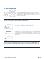
7. Menu navigation and operation
Cursor control
The Secvest menu is mainly navigated using the cursor keys located below the display:
These keys are used to scroll through the menus and activate specific scenarios when the system is
being armed, amongst other functions. More information is provided in the next chapter, "Arming and
disarming the system".
These keys are used to select menus or symbols, change values and also exit the menus again. The
function of both keys adapts dynamically to the text shown on the display. If, for example, "Menu" is
key below and enter your user code. This brings you
shown on the left side of the display, press the
to the user menu which you can exit again by pressing the
key.
8. Arming and disarming the system
8.1 Arm/disarm keys
The arm/disarm keys for the alarm panel are located below the cursor field. These keys can be used to quickly
and conveniently arm or disarm the alarm panel. Additional arming options are covered in detail below. In
the standard configuration, Secvest is armed on a time delay, meaning it is only armed after the exit delay
programmed by your specialist installation contractor has expired.
T his key is used to start "internal arming". Only the detectors for "perimeter protection" are activated,
so that you are still able to move around the building freely (even if there are motion detectors installed
indoors, for example).
T his key is used to quickly arm the complete system. No user code is required for this. Note that when
this key is pressed ALL detectors including those in all sub-areas (if there are any) are activated. This
function will only work if the key has been enabled in consultation with your specialist installation
contractor. This key has no function if it has not been enabled beforehand. If necessary speak to your
installation contractor if this key function is required.
T his key is used to disarm the system again. After the disarm key is pressed you must enter a valid user
code. The complete system is then disarmed (including all sub-areas).
7. Menu navigation and operation | 8. Arming and disarming the system
62 | 63
8.2 Graphical display of arming/disarming on the display
This section contains information on how the arming or disarming of the alarm panel is shown on the
display. This assumes that your system has been configured with just one sub-area. All detectors are therefore
assigned to sub-area 1. In this case sub-area 1 is the entire premises.
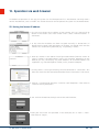
8.3 Arming/disarming via the quick arm keys
1. If the system is disarmed, the display responds as follows: the open padlock
symbol indicates the disarmed status of the alarm panel.
2. If the
key is then pressed, the system is completely armed. As mentioned
previously, the system is armed only once the delay time has expired as
programmed by your installation contractor.
3. You should leave the premises within this time delay. The closed padlock
symbol then indicates the armed status of the alarm panel. To disarm the
alarm panel again, simply press the
key and enter a valid user code. The
system is then disarmed with the audio message, "The alarm system is
disarmed" and the open padlock symbol visually indicates this status.
This method of arming the system as described here using the quick arm keys is one of the fastest and provides
a representative example of how system arming works in general. The next section provides information on
other ways to arm the system. Not all of these options may be available, as they depend on the configuration
of your system by the specialist installation contractor. If necessary speak to your installation contractor if you
desire a specific method of arming your system.
8. Arming and disarming the system
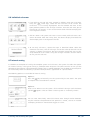
8.4 Arming via the user code
1
2
3
4
5
6
7
8
9
*
0
#
The system can be armed by directly entering a user code. The
system has either been configured with a 4 or 6-digit user code in
consultation with your specialist installation contractor. The standard
user code is "1234" or "123456" depending on whether a 4 or 6-digit
code has been programmed.
This code should be changed during commissioning, however. If a new user is added, a separate code is
created for this user. Every user should take note of their individual codes.
1. To arm the system, simply enter a user code. Please note that the "menu"
key is not pressed before entering this code. Otherwise you will be directed
to the user menu, from which you cannot arm the system.
2. After the code is entered the "delay time" starts (in the standard configuration
of the system). You should leave the building within this time delay. For this
reason, ensure that sufficient time is planned to exit the building. If, for
example, 35 s has already passed and you still have to get out the door, there
is not enough time. A false alarm may be triggered, as the opening and
closing of the door along with the transmission of information takes a bit of
time in itself.
3. If the delay time has expired, the system is armed: you have now successfully
armed sub-area 1 and can disarm it again by entering a user code.
If a window is still open, for example, when the alarm panel is armed, an error message is displayed.
Correct the error (close the window) and then rearm the alarm panel. If the error cannot be corrected, you
can arm the alarm panel anyway by pressing the "Lock all" key. In this case the alarm panel is armed with
"hidden zones". This means that all open detectors or detectors with faults are ignored during monitoring.
These detectors will not trigger an alarm in this case! These zones only remain hidden until the next time
the system is armed.
8. Arming and disarming the system
64 | 65
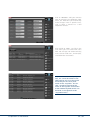
8.5 Arming sub-areas
In addition to the option of arming a sub-area via a user code, the system can also arm additional sub-areas.
The procedure for this is given here using the user code entry example. This function must be preconfigured
by your specialist installation contractor.
After entering the user code, you are asked to confirm which sub-area(s) you wish to arm. Alternatively you
can also arm the complete system when, for example, you plan on leaving the premises altogether.
The following explains how to arm one or more sub-areas:
1. In our example the alarm panel is divided into 4 sub-areas. These are
displayed as disarmed by the open padlock symbol. First enter your user code
as usual:
2. O
nce the user code has been entered, the menu changes as follows:
3. Select "Change" and the display changes as shown in the figure on the left.
Click "Done" to arm all sub-areas. The system is now completely armed.
4. If you only wish to arm certain sub-areas, click on "Change" and use the
key to navigate through the four sub-areas until the sub-area you wish to
arm is selected. Click on "Done" to arm the selected sub-area. Repeat the
same procedure to arm other sub-areas.
8. Arming and disarming the system
8.6 Individual sub-areas
1. If you wish to arm two sub-areas, proceed as follows: enter your user code.
Using the
arrow keys, select the two sub-areas to be armed. The
selections
are visually highlighted. Set the selected sub-areas to the
open padlock symbol via the "Change" function. Leave the sub-areas you do
not wish to arm "empty". In this case the menu looks like the example given
in the figure on the left.
2. Click on "Done" and system sub-areas 1 & 3 are armed, while sub-areas 2 & 4
remain disarmed. After the arming time, the Secvest display then looks like
the example given in the figure on the left.
3. To arm only sub-area 2, repeat the steps as described above. Select the
individual sub-areas, click on "Change" and set the value for the sub-area to
"empty" as shown in the figure. The sub-area to be armed (sub-area 2 in this
case) should be set to "active" using the "Change" function. Click on "Done"
to arm just this sub-area.
8.7 Internal arming
In addition to the option of arming the complete system and sub-areas, the system also offers the option
of "internal arming". This type of arming is preferred when occupants are home and wish to arm just the
perimeter of the premises. Certain detectors indoors (such as motion detectors) are disabled so that occupants
can move freely within the building. A practical example here is application in a private home.
The following options are available for internal arming:
Option 1:
Press the
key to internally arm the system with just one touch. The quick
arm option must be enabled in advance.
Option 2:
Enter a user code to arm the system. Click and hold "Change" until the house
symbol
appears. Click on "Done" and the system is "internally armed".
You can now move freely around the house even though motion detectors
may be installed. The perimeter of the premises is armed, so that an intruder
attempting to break in from outside triggers an alarm.
8. Arming and disarming the system
66 | 67
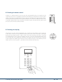
8.8 Internal arming via chip key
The procedure for internal arming via the chip key is virtually the same as arming the
complete system: Hold the chip key in close proximity to the ABUS logo and swipe it
over the logo briefly. A prompt appears, requesting confirming on the type of arming
required. Click on "Change" as usual and select the house symbol. Click on "Done"
to arm the system internally.
8.9 Internal arming via remote control
On the remote control, the * key is assigned the "internal arm" function as standard.
This symbol is on key 2 of the remote control. Simply press the key and the system
is internally armed. Visual feedback is provided next to the * symbol: brief flashing
(green) for sending the signal, then flashing (red) to indicate successful internal
arming.
8.10 Arming via wireless control panel
An additional way of arming the system is provided via the optional wireless control
panel. This arming/disarming option is as similar as possible to the other system
options. Only the operation method is different, as the wireless control panel does
not have a display. Please read the individual operation options in the user manual for
the wireless control panel.
8. Arming and disarming the system
8.11 Arming via remote control
If there is a remote control, you can press the corresponding keys to arm/disarm the
system (all sub-areas are armed/disarmed simultaneously) and internally arm the system
if you as the user are authorised to do so. You can also check the status of the system.
The remote control provides visual system feedback for all entries ("2WAY function"). For
a detailed explanation of the individual functions of your remote control, please read
the user manual for the remote control.
8.12 Arming via chip key
The chip key can be used to completely arm and disarm the wireless alarm panel (or
a sub-area, if there are any) without touching the panel itself. The chip in principle
eliminates the need to enter a code. If you as the user to whom the chip is assigned
are authorised to arm or disarm multiple sub-areas, you must then decide which area
to arm after you have swiped your chip key. The reader area for the chip key is located
at the height of the ABUS logo. You only have to swipe the chip in the proximity of the
reader area to arm the system – you do not have to touch the housing.
8. Arming and disarming the system
1
2
3
4
5
6
7
8
9
*
0
#
68 | 69
8.13 Arming via delay times
If you enter a code directly on the alarm panel (or via chip key or quick arm keys), the following "problem"
occurs: you must still be able to leave the premises through the doors. If the system were automatically
armed, you would not be able to leave the premises without triggering an alarm, if you have a magnetic
contact on the doors, for example. For this reason there is a "delay time". The delay times are preconfigured
by your specialist installation contractor.
There are generally two delay times:
• Exit delay
• Entry delay
The exit delay is set to 40 s as standard (the time can be adjusted by the specialist installation contractor
according to your needs, however). You must leave the premises within this time after arming the alarm
panel.
Ensure that all windows and doors etc. are closed first before arming the alarm panel. After the alarm panel
is armed, a continuous tone sounds. This tone is briefly interrupted when the doors are opened and closed
and then continues. Make your way out of the building and open and close the doors in time.
Important: if the exit delay has expired and you are still inside the building, your movement, for example,
will trigger an alarm if detected by a motion detector.
The entry delay gives you a sufficient timeframe to disarm the system after opening the doors when the
system is armed. The entry delay should also be programmed in consultation with your specialist installation
contractor. Ideally the entry delay should be as short as possible. If you enter your premises through the
doors, you should hear a pulsed tone. As long as this tone sounds you have time to disarm the system. Disarm
the system using your code (or chip key/disarm key).
Important: if the entry delay expires without the system being disarmed, an intruder alarm is triggered.
The system also allows a special type of exit delay: the system is only armed once the doors are closed. The
exit delay is therefore flexible to allow you to take whatever time you need to get out the door. Speak to your
specialist installation contractor if you desire this type of arming.
8. Arming and disarming the system
9. Responding to an alarm
First of all: remain calm. An alarm does not always mean an intrusion. An alarm could be caused by something
else, such as a self-triggered false alarm. For this reason, get a feel of the situation first and then respond
accordingly in a composed manner. Disarm the system, check the reason for the alarm and then reset the
alarm.
If an alarm is triggered, first disarm your alarm panel by entering a user code, for example. You will then be
prompted to "reset" the alarm panel. This means that you must still "acknowledge" the alarm on the system
in order for it to be ready for operation again.
The alarm is then shown on the display. "T2" means that an alarm has been triggered in sub-area 2. "Intrusion
Z02 alarm" means that an intruder alarm has been triggered in "zone 02" in this sub-area. This "zone 02" is
the second detector in the system, with the name "MC kitchen" (magnetic contact in kitchen). You can now
go into the kitchen to see what exactly has happened near this detector.
If the cause of the alarm is clarified and corrected, click on "Reset". The system
is then reset and ready to be armed again. Note that a reset is necessary. If this
is ignored (e.g. if you click "Exit") the reset does not take place properly and
appears automatically during the next arming process. If no entry is made, the
graphical display disappears after 1 minute but remains on the system.
Important: occasionally you may find that an alarm cannot be reset. This may occur, for example, if the
housing of your alarm panel and its components have been opened and a tampering alarm has been
triggered. This can be corrected only by your specialist installation contractor.
9.1 Alarm types
An alarm can have various causes. The following alarms exist in principle:
•
•
•
•
•
•
•
•
Tampering alarm
Intruder alarm
Panic alarm
Technical alarm
Fire alarm
Emergency call or medical emergency alarm
Entry delay exceeded
Exit delay exceeded
The Secvest has four different types of alarm. Depending on the status of the system (disarmed, armed,
internally armed), the following alarms are available (depending on the setup or programming of the alarm
panel):
9. Responding to an alarm
70 | 71
Internal
Local
External
Silent
Alarm panel siren
ü
ü
ü
–
Indoor siren
ü
ü
ü
–
Outdoor siren
ü
ü
ü
–
Wireless control panel
ü
ü
ü
–
Information module
ü
ü
ü
–
Visual alarm, such as flashing light
ü
ü
ü
üopt.
Diallers, such as monitoring station switching, text message, email, etc.
üopt.
üopt.
ü
ü
Relay
üopt.
üopt.
üopt.
üopt.
9.2 Alarm forwarding
If the communication interface of the Secvest has been programmed (speak to your specialist installation
contractor), the following alarm forwarding options are available (depending on the configuration of your
system and the connection used, such as IP, PSTN):
•
•
•
•
•
Alarm forwarding via telephone (analogue or VoIP)
Alarm forwarding to a monitoring station (MS)
Alarm forwarding via email
Alarm forwarding via text message
Emergency call: emergency switching to medical services (e.g. Tunstall)
9.2.1 Alarm forwarding via telephone
With alarm forwarding via telephone you receive a telephone call and hear a message (recorded by you or
the specialist installation contractor), for example: "Intruder alarm at bathroom window. Please arrange
help." Proceed as follows:
1. The call occurs on the telephone and is displayed there like any other call.
2. Accept the call.
3. Listen to the entire message. The message is different depending on the cause of the alarm.
4. The recorded text is repeated three times. After the third time, the microphone on the alarm panel
is enabled and you can listen to what is happening in the room. You also have the following key
commands available (your telephone must be DTMF-compatible):
Telephone key (DTMF)
Meaning
Listen
1
Speak
2
Toggle between "Listen" and "Speak"
*
Playback messages
3
End call
5
End all calls
9
9. Responding to an alarm
5. If you feel capable of resolving the problem yourself, acknowledge the alarm transmission by pressing 5 or
9. 5 means that the attempt to call you is stopped. Other contact numbers on the system may be called,
however. 9 means that the attempt to make any calls is stopped. No other contacts are called.
6. If you cannot resolve the problem yourself, press 5 in any case. The alarm is forwarded to additional people.
You can "remotely control" the alarm panel via the telephone keypad (if this function is enabled). For more
information, see "Advanced system operation".
9.2.2 Alarm forwarding to a monitoring station
If switching to a monitoring station is implemented, the monitoring station (MS) takes care of acknowledging
the alarm transmission and coordinating help. Speak to your specialist installation contractor if you have
questions about monitoring station switching.
9.2.3 Alarm forwarding via email
If the Secvest is connected to the internet (e.g. via a router), it can also forward an alarm via email. The alarm
panel text (e.g. "Intrusion Z01 alarm") is sent to a predefined email address. If you are also using the Secvest
PIR camera, the alarm image can also be attached to the email. Contact your specialist installation contractor
if you wish to set up this function.
9.2.4 Alarm forwarding via text message
Similarly to email transmission, alarms can be forwarded via text message (for example using the optional
GSM module).
9.2.5 Alarm forwarding in the event of a personal or medical emergency
If your household includes a vulnerable person, you can also set up forwarding for local alarms to a monitoring
station specialised in handling medical emergencies. A known provider for this type of service would be
Tunstall, for example. Speak to your specialist installation contractor about setting up this function.
9. Responding to an alarm
72 | 73
10.User menu
The user menu helps you configure certain basic functions of the system. You can create and manage users,
set the date and time and add and remove contacts.
There are two different "levels" of the user menu. Log in as an "administrator" to delete other users, for
example. Log in as a "normal user" to use the system with limited options in certain menus – you cannot edit
or delete other users in this mode. Certain menus are not accessible for "normal users", such as "Contacts"
and "Info". The administrator is in charge of managing these menus.
The following contains an overview of the structure of the user menu and the options provided by these
menus when you are logged in as an administrator:
1. To log into the user menu, select "Menu" and enter an admin code. The first
menu appears.
2. As a system administrator you can manage users and create new users. Log
into the user menu with your admin code (the default code is "1234" or
"123456") and go to the "Users" menu.
3. To add a new user, select "Add user". You are then guided through the setup
options for a new user step by step.
4. User name: Using the Secvest keypad, enter the name of the user.
5. Select which user level the new user will have: Normal user: a normal user
has limited options compared to an administrator. Normal users cannot
create new users or edit existing users other than themselves, but they can
change their own codes and assign remote controls, for example.
Administrator: an administrator has advanced options in the user menu.
Administrators can create new users and edit existing users. There are also
more advanced options in other menus, such as in the system configuration.
Usually one administrator per household is sufficient. If the premises involve
a commercial property with multiple employees, for example, it may be a
good idea to create additional administrators.
10. User menu
6. The next step involves assigning arming/disarming authorisation for subareas. Select "Done" if the user will be authorised for all 4 sub-areas.
Otherwise make adjustments using the "Change" function.
7. Assign an access code. This code should ideally be changed by the user
themselves and kept safe by them. Ensure that the code is "secure". Code
combinations such as "5678" are less secure than "2671", for example.
For a higher degree of security, the system can be preconfigured to accept
6-digit codes. Speak to your specialist installation contractor if your system is
configured for only 4-digit codes. A 4-digit code is created in this example.
This code must be confirmed once after it is first entered. Alternatively you
can also select "No code". In this case the user can only arm the system via
chip key or remote control.
8. Additional components can be assigned to the new user. The first prompt is
for a chip key. Take the chip and swipe it across the ABUS logo in close
proximity to the housing. If no chip key is desired, select "No chip key".
9. A remote control can then be assigned. Press any key of the remote control.
If no remote control is desired, select "No remote control".
10. Social care emergency call: if your household includes a vulnerable person,
you can give them a mobile emergency call button. This button is used to
quickly trigger an internal alarm if the person in question suddenly needs
help. Press the emergency call button key once to assign it.
11. Panic alarm button: you can also use the emergency call button as a panic
alarm button. Note that if the button is already being used as an emergency
call button, it cannot also be used as a panic alarm button at the same time.
12. Medical emergency call: you can also use the emergency call button/panic
alarm button as a medical emergency call button. Note that if the button is
already being used as a social care emergency call button or panic alarm
button, it cannot also be used as a medical emergency call button at the
same time.
13. The following confirmation then appears: "New user added". You can create
additional users in the same way.
10. User menu
74 | 75
10.1 Editing users
The administrator can edit existing users here, such as assign a remote control
or change a name after having created the user previously. Use the cursor keys
to select the user to be edited. Select "Edit user" and then you can choose
between the following options: "Name", "Code", "Chip key", "Remote control",
"Social care emergency call", "Panic alarm" and "Medical emergency call".
10.2 Removing users
To remove users (such as an employee who has since stopped working at the
premises), select the user in question and remove them from the system. All
components assigned to this user, such as remote controls, are automatically
deleted.
10.3 Creating a user "threat code"
In addition to the user levels of "normal user" and "administrator" you also
have the option of creating a "threat code". This code is used to seemingly
disarm the system during a hold-up when the intruder is watching. A silent
alarm is still triggered in the background, however. For this function to be
enabled, an appropriate communication interface (e.g. telephone or monitoring
station switching) must be set up. The steps for setting up a threat code user are
the same as those for setting up any other user. Proceed as follows:
User menu -> Add user -> Name -> "Threat code user". Create a code for this
user. This code should be known to all users of the alarm panel. Then if an
intruder enters the premises and forces you to disarm the alarm panel, simply
enter this "threat code". The system appears to disarm as normal. The silent
alarm is triggered via telephone switching, however.
Important: This function must be enabled beforehand by your specialist installation contractor in order for
the "Threat code user" option to appear in the user menu. If in doubt contact your specialist installation
contractor if this option does not appear in the menu.
10. User menu
10.4 Voice memo
This function is used to leave someone else a message ("Memo function").
Record a short reminder, for example, and then arm the system. The next person
to disarm the system is notified with the text "You have a message" and a
corresponding symbol. Select "Recording" to record a 30-second message and
then save it. Any user can delete this message after it has been played back. This
function can be completely disabled in consultation with the specialist
installation contractor.
10.5 Hiding zones
It may occasionally be necessary to exclude a detector (also called a "zone")
from monitoring, for example if a detector is faulty or a zone cannot be closed
for some reason. The system then indicates the detectors that can be hidden.
The setting is indicated as follows: Ü = monitored and G = locked (not monitored).
Select the detector to be hidden and press "Change". Note that detectors to be
hidden manually must first be configured for this function by the specialist
installation contractor. For this reason not all of the detectors in the system may
appear in the list of detectors which can be hidden if this has been set up that
way beforehand. If detectors are hidden, they are no longer monitored when
the alarm panel is armed. A hidden detector is "unhidden" the next time the
system is disarmed and must be hidden again manually to be excluded from
monitoring the next time the system is armed, if desired.
10.6 System configuration
The following settings can be defined in the system configuration:
• O
n/off functions: settings for certain special functions such as door bell,
voice messages, etc.
• Date & time: setting for the date and time
• Remote controls: reprogramming of key assignments for remote controls
• Volume settings: setting for the volumes of different tones and messages
• Web access: activation/deactivation of web access
• Time schedules active/inactive: configuration of time schedules for
automatic arming/disarming
10. User menu
76 | 77
10.7 On/off functions
Click on "On/off functions" to access the following options which are explained
in the sections that follow:
• Bell
• Voice message
• Activity monitor
• Display contrast
• Backlighting brightness
• LCD backlighting
• Backlighting for menu keys
• Backlighting for arm keys
• Backlighting for number keys
• Zone name announcement
10.8 Bell
If the "Door bell" property is configured for a detector (e.g. for a magnetic contact at the entrance of a business), the disarmed alarm panel triggers a tone similar to a door bell. This function must be configured by
the specialist installation contractor. This indicates that someone has entered the business premises. If you
wish to disable this function for a certain time period, it can be disabled here.
10.9 Voice message
In this menu you can disable the audible messages on the alarm panel (e.g. "Please note the message on
the display").
10.10 Activity monitor
If the "Activity monitoring" property is configured for a detector (e.g. a motion detector in the hallway),
the function of a motion detector can be "reversed". This function must be configured by the specialist
installation contractor. If the function is reversed, an emergency call alarm is sent after a defined time period
in which no movement has been detected. This function is used to monitor older, vulnerable members of the
household. After a defined time period, an emergency call is sent when the regular "presence detection" at
a previously designated motion detector has not triggered. This allows vulnerable members of the household
who generally spend their time moving around a specific room to receive help quickly if their "presence" is
not detected after a certain time due to a fainting spell or something similar.
10.11 Display contrast
Change the contrast of the Secvest display here.
10.12 Backlighting brightness
Change the brightness level of the display here. You can choose between "Low", "Medium" and "High".
10. User menu
10.13 LCD backlighting
Set the lighting of the display here. "Off" deactivates the lighting completely. "On" activates the lighting so
that the display is constantly lit. "When active" means that the display lighting remains activated for approx.
30 s after each operation and then automatically switches off.
10.14 Backlighting for menu keys/backlighting for arm keys/backlighting for number keys
The same setup as for "LCD backlighting" applies here for the backlighting of the menu keys, arm/disarm keys
and number keys. Set the desired lighting of the keys for menu navigation.
10.15 Zone name announcement
Your detectors can be equipped with an additional audio message if desired. In consultation with your
specialist installation contractor, the detectors are usually already given a name, for example "MC living
room" for "magnetic contact in living room". This text can be recorded and saved here individually for each
detector, with approx. 2 s allocated for each detector. If detector "MC living room" triggers an alarm, for
example, the text not only appears on the display when the alarm is disarmed, but the name of the alarm
is also audibly played back. Do not forget to select "Playback" after recording the detector text to check what
was recorded and ensure it is correct and intelligible.
10.16 Date & time
Set the time and date here. Both can be entered directly using the number keys. Click on "Next" to navigate
through the menu. Then define whether the system automatically adjusts for daylight saving time or whether
you wish to adjust the system manually yourself. We recommend setting it to adjust "Automatically".
10.17 Remote controls
Assigned remote controls can be edited or removed here. The following options are available:
• Edit: press the * key of the remote control to reprogram it. The standard setting of the key is "Internal
arming". If you wish to switch a relay output with this key instead, however, this function can be
assigned to this key. A suitable relay output must first exist in the system. Speak to your specialist
installation contractor if you require this function, such as to open the garage door via a relay output.
• Remove: remove a remote control that has been lost or is no longer needed. If you still have the remote
control, press any key. If you have lost the remote control, press "No remote control" to delete it without
having to press a key.
• Remove all: you can delete all remote controls in the system at once here.
• Panic response: if the remote control has a panic alarm, this function can be disabled here. The "panic
alarm" on the remote control can be triggered by pressing both padlock keys at the same time.
10. User menu
78 | 79
10.18 Volume settings
Set the volume of different tones here. The tones can be changed by directly
entering a number from 0–9, where 0 means muted and 9 represents maximum
volume.
Operation tones: refers to all tones that occur when the system is being operated,
such as the feedback tones when operating the system via the keypad.
Info tones: refers to all info tones, such as feedback tones for error messages.
Alarm tones: the volume of the alarm tones (intrusion, fire, etc.) can be changed
here. The volume of the messages can be changed by clicking "Select" and then
adjusting the volume using the +/- keys.
We recommend leaving alarm tones set to "9". If you set the volume of the alarm tones too low, you may
not hear an alarm in time or at all.
10.19 Web access
Define whether your system can be operated remotely (see "Web access") or not here:
• Locked: • Unlocked: web access disabled
web access enabled
10.20 Time schedule active/inactive
You can enable the "week planner" in this menu. For example, if on Monday to Friday you want the system
to disarm at 7am and then arm at 6pm (a typical timeframe for a shop), you can set this up here.
We recommend setting up the week planner via the web interface (see "Web access"). "Web access – Time
scheduler" describes the setup of the week planner in detail.
10. User menu
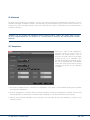
10.21 Contacts
You can manage your contacts in this menu. Use the telephone/IP interface or
similar of your Secvest, for example, to forward alarms. The contacts can be
adjusted here or new data entered. Not all fields must be completed.
Select "Contacts" to access the following menu:
You can choose up to 12 contacts. Usually the contacts are initially set up in
consultation with your specialist installation contractor. Using the example of
"Contact A", the following options can be seen:
•
•
•
•
•
•
Name: enter the name of the contact
Tel.No.1: enter telephone number 1 of the contact
Tel.No.2: enter telephone number 2 of the contact
Email: enter the email address of the contact
IP address: this is the IP address of the monitoring station. Do not change this entry.
SIP user ID: if VoIP is used, the "User ID" is entered here.
Important: only make changes to contact entries, such as when a number has changed or the contact can
no longer be reached. The "IP address" is usually assigned to an MS (monitoring station). Do not make
changes to this if you can avoid it!
10.22 Test
The test menu provides the option of testing the various functions of your system to ensure they are working
properly. Depending on the setup level of your alarm panel, certain functions may not be available.
Select "Test" to access the following menu:
The following options are available:
• Walk test
• Sirens & sounders
• Door locks
• Outputs
• Chip key
• Remote controls
• Emergency buttons
• Telephone call
10. User menu
80 | 81
10.23 Walk test
1. You can test your detectors in the "walk test". For example, if you want to know
whether a certain detector is functioning, you do not have to trigger an alarm.
Simply select "Walk test" and test the detector. We recommend proceeding as
follows: Open the walk test and activate the "Bell - on" menu.
2. A feedback tone sounds in this case when you trigger a detector during the
walk test.
3. S elect "System" and your detectors should be listed (depending on the setup level
of the system you may not see all detectors – in this example you see 4).
4. Then open the window with the first detector (such as a magnetic contact).
For a motion detector you should move around briefly within its detection
range. Repeat this for all detectors (you may have to do different things to
trigger them depending on the type of detector). After a successful test the
menu should look like the example shown on the left. In this case "A" stands
for a "virtual alarm" that was triggered. The detector is working properly. If
there is no entry "A" for a detector and you have tested all detectors, repeat
the test for the detector in question again. If the entry fails again, contact
your specialist installation contractor.
Important: ensure that you do not open the housing of a detector. Otherwise the system automatically
exits the walk test and triggers a tampering alarm. Detector housings are only opened by the specialist
installation contractor for maintenance purposes.
Under "Sub-areas" you can select whether only detectors from a certain sub-area are tested. Under "Zones"
you can select whether only certain detectors are tested. The procedure is then the same as for the walk test.
10.24 Sirens & sounders
Test the function of different sirens and sounders here. Click on "Change" to test the following:
• Internal sirens: test the installed sirens of the alarm panel and any indoor sirens here.
• External wireless
sirens:if at least one wireless siren exists in the system, it can be tested here. We
recommend only briefly testing this function. Warn your neighbours before
testing if necessary.
• Siren module:if a universal module (UVM) is installed as a "siren module", you can test its
function here. Warn your neighbours before testing if necessary.
• Loudspeaker: Test the installed loudspeaker of the Secvest here. Select "Playback/Stop" to
hear all existing messages in the system one after the other.
10. User menu
10.25 Door locks
If a Secvest key and/or additional door lock is installed, it is a good idea to check its function occasionally.
Engage the lock while the alarm panel is disarmed – the message "Open" or "Closed" is displayed.
10.26 Outputs
If a relay output is enabled this menu appears here. Click on "Select" and test the output using the "On/off"
function. If relay contacts (from the Secvest, universal module or wireless socket) have been enabled by the
specialist installation contractor, you can test these if necessary. The corresponding relay contact must be
enabled for you as the user in order to test it. There are relay contacts that only activate when an intruder
alarm is triggered and therefore cannot be accessed in this menu. Speak to your specialist installation
contractor if you wish to access a relay contact, for example to use a wireless socket for lighting control.
10.27 Chip key
If your system has a proximity chip key and you wish to test its function, take the key and swipe it over the
chip key reader area in the lower area of the alarm system (at the height of the ABUS logo). If the chip key is
read successfully, the display indicates which user the chip key is assigned to.
10.28 Remote controls
If you wish to test the function of a remote control, select this menu and press the different keys one after
the other. The display then indicates which keys have been pressed and what function is assigned to the key
in question. The standard assignment of the remote control is:
Closed padlock
Complete arming
Star key
Internal arming (= perimeter protection on)
? key
Status query
Open padlock
Complete disarming
The user assignment is also displayed and the signal level of the triggered remote control, e.g. RSSI:9. RSSI
stands for "received signal strength indication". An RSSI value of "9" indicates an excellent received signal
strength, as the scale for the Secvest runs from 1–9, where 9 is the maximum strength.
10. User menu
82 | 83
10.29 Emergency call button
An existing emergency call button (for social care, panic alarm or medical emergency) can be tested here by
pressing the emergency call button. Depending on which function has been assigned to the emergency call
button, the function of the button is displayed. For example, "PFN alarm" (PFN = social care emergency call).
As with the remote control, the RSSI and user assignment are also displayed.
10.30 Telephone call
If you system is equipped with an active telephone interface (e.g. GSM or VoIP), you can test the function of
the connection by making a test call. Enter any telephone number. If the connection is successful you get a
dial tone and can make the call. If the connection is not activated or is otherwise disrupted, you get the error
message "Communication error". Check the other telephone connections in the house if there are any and
contact your specialist installation contractor if necessary.
10.31 Log book
You can view the "log book" in this menu. The log book contains all of the
relevant data for the alarm panel including the date and time. The memory can
hold up to 600 entries. If the memory is full, the oldest entry is deleted and
overwritten with the new entry ("first in first out" principle).
A list of the different log book entries can be found in the appendix under "Log
book overview".
10.32 Info
This menu is used to check the software version of the wireless alarm panel and
query the communication interfaces. You cannot change any configurations in
this menu. You can only view the following information: Info => Alarm panel
=> Version:
•
•
•
•
Version: S/N: Part No.:
Language:
software version, e.g. v0.00.18
serial number of the alarm panel, e.g. FUAA50000#E……
article number of the alarm panel, e.g. FUAA50000
set language including language version, e.g. English v0.13
PSTN: Info => Communication => PSTN
Queries the PSTN link status. The Secvest then checks the installed landline. If it
is not enabled or is disrupted, the error message "Error" appears. Otherwise the
message "Test successful" appears.
10. User menu
SM: Info => Communication => GSM (This menu only appears when the GSM
G
module is installed.) You can query information about the GSM module here,
such as IMEI, SIM card number (if supported by the provider) and network
operator. Select "Network", for example, and the network operator and signal
level are displayed.
The signal level in this case ranges from 1 (very poor reception) to 10 (excellent
reception).
10.33 Ethernet Info => Communication => PSTN
If the system is integrated in a network via a network cable (e.g. via the router in the home network), you
can view the items listed below. Speak to your specialist installation contractor if in doubt, as for some of the
listed values specific knowledge of networking is required.
10.34 IP address
If the Secvest is located on a network the IP address is shown here, e.g. 192.168.178.23. If (DCHP) is shown after
this in brackets, the Secvest automatically obtains its IP address from a DHCP server, for example, in a router.
If the Secvest is not networked, "0.0.0.0" is displayed here.
10.35 IP subnet mask
The subnet mask is displayed here. In a private network this is normally 255.255.255.0.
10.36 Gateway IP address
If the Secvest is located on a network the IP address of the gateway is shown here. An example of a gateway
in a private network is the router, e.g. the Fritz!Box.
10.37 DNS primary IP address
This is the IP address of the Domain Name System (DNS).
10.38 MAC address
The hardware address of the network adapter for the Secvest is given here. A MAC address is globally unique.
10.39 IP link status
The message "OK" appears if the Secvest has a functioning network connection. "Error" appears if the
network connection is disrupted or the Secvest is not connected to the network at all.
10. User menu
84 | 85
11. Advanced system operation
11.1 Remote control
If you have a remote control, the wireless alarm system can be armed or disarmed by
pressing the remote control keys.
Key 1
Arm
Key 2
Arm internally (or "Switch output". The key must be
reprogrammed for this function in this case.)
Key 3
Status query
Key 4
Disarm
11.2 Wireless cylinder ("Secvest key")
Arming
The wireless cylinder can be used to easily arm the system. To arm the alarm panel, first press the button on
the cylinder and then lock the doors. Once the doors are locked the alarm panel is armed.
Disarming
Likewise, you can completely disarm the system by opening the doors. Open the doors as normal. The wireless
cylinder transmits the signal to disarm the alarm panel, which disarms the system immediately.
11.3 Additional door lock (FU7010/7025E)
If a wireless additional door lock from ABUS is installed, you can arm and disarm the system in a way
similar to the wireless cylinder. The additional door lock provides a high degree of
electromechanical security as it ensures intruders are met with up to one tonne of
pressure resistance and also triggers an alarm if there is an attempt to force the door
open with a lever.
For more detailed information on this product's operation, see the relevant instruction manual. The
practical steps are described here briefly.
Arming
To arm the alarm panel, lock the doors from outside using the key. After 2 complete revolutions from outside the
system is automatically armed. Depending on the article number of the product, the system can also be armed
from inside: for FU7010 (with rotary knob) you need one revolution, for FU7025 you need two. Important: if you
wish to leave your premises very briefly but still want to lock the additional door lock, you must press the key for
"suppressing arming". The door look must then be activated within 30 s so that the system remains disarmed.
11. Advanced system operation
Disarming
To disarm the alarm panel unlock the additional door lock accordingly. Unlocking the lock automatically
disarms the alarm panel.
11.4 Operation via telephone
If the alarm panel is connected via the A/B interface, the wireless alarm panel can call you to
report an alarm. Once you have listened to the message, you can send commands to the system
by pressing the keys on your telephone keypad. The system sends information about the status
of your commands by playing back the voice messages (e.g. "Reset required"). You can also call
your wireless alarm panel if no alarm call has taken place, in order to check your alarm system:
1. Select the alarm system telephone number. You should then hear three beeps in succession.
2. Enter the access code via the telephone keypad. You should then hear two beeps in succession.
You can then use all of the following commands upon consultation with your specialist installation contractor.
The specialist installation contractor may still need to enable these commands before they can be used:
Function
Key combination
Listen
1
Speak
2
Toggle between "Listen" and "Speak"
*
Playback messages
3
End call
5
End all calls
9
Disarm system
#0*0
Arm system
#0*1
Internally arm system
#0*2
Stop sirens
#1*0
Reset system
#1*1
Query system
#3*
Switch output nnn to "On"
#9*nnn1
Switch output nnn to "Off"
#9*nnn0
Toggle output nnn
#9*nnn*
If you are called by the alarm panel in the event of an alarm, you do not need to enter the access code.
However, you can operate the system using key combinations 1, 2, 3, 5 and 9. Key combinations #0*0 etc.
must first be enabled by your specialist installation contractor before they can be used.
11. Advanced system operation
86 | 87
12.Operation via web (app/browser)
The Secvest can be easily and conveniently operated via the internet or a local network using the integrated
network interface. To use these functions, the Secvest must be integrated in a network and configured
accordingly by your specialist installation contractor. If you have any questions, please contact your specialist
installation contractor. The following describes which options are available for operating the system via the
network and how these options function.
In principle you should have these options for operating the system:
12.1 Operation via web browser
If you can access your home network (e.g. the WLAN) from a computer, smartphone or tablet and the Secvest
is also located on this network, you can access the web interface of the Secvest by entering the IP address of
the Secvest in your browser (e.g. Firefox). The web interface can be used to operate the Secvest for arming
and disarming the system with all the control options available directly on the alarm panel (see "Basic
operation"). You can also switch to the user menu level and define settings via the web interface. You have
virtually the same options as on the system itself in this case.
12.2 Operation via app
The second option for operating the Secvest via the network
is to access it via the Secvest IP app. You can purchase the
app in the iTunes or Google Play Store (account required). Once
installed and set up on a smartphone or tablet, you can do the
following things with the app:
•Arm/disarm the system completely
•Internally arm/disarm the system
•Arm/disarm sub-areas
•Switch outputs
•Submit status queries
•etc.
As with operation via web browser, access to the system via
network must be set up beforehand.
The following pages provide a detailed description of the
procedure for both options.
12. Operation via web (app/browser)
13.Operation via web browser
In addition to operation via the app, the system can also be operated via a web browser. You only need a
normal web browser, such as Firefox. This section discusses how to operate the system via the web browser.
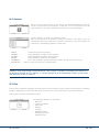
13.1 Setting the Secvest IP address
1. First you must know the IP address of your Secvest. This can most easily be
found in the Secvest user menu under "Info": select "Communication" ->
"Ethernet".
2. In this case the IP address has been assigned manually as 192.168.178.4. If
(DHCP) were to appear after the address in brackets, this would mean that the
address was automatically obtained (e.g. assigned by a router).
3. Enter this address in the address line of your web browser (without "www" or
"http"). Firefox is the web browser used in this example. Depending on the
browser you use, the display may look different. All standard browsers are
supported, e.g. Internet Explorer. Firefox, Safari, Chrome and Opera.
4. Usually there is a message indicating that the connection is "untrusted". This
does not mean that the connection between the PC and Secvest is not secure.
5. Click on ""I Understand the Risks" and then "Add Exception". Then click on
"Confirm Security Exception".
6. You are then directed to the login area of the web interface.
7. Enter your user name and password. In our example, this is "1234" / "1234".
Then click on "Login".
13. Operation via web browser
88 | 89
8. You are then directed to the main menu of the Secvest. The next page provides
an initial overview of the different options available to you at this level.
13.2 Overview of the web interface
The web interface is very similar in its functional scope to the user menu. The control panels and menus are
rearranged, however, in order to provide a more user-friendly display on the web interface. If you are familiar
with the functional scope of the Secvest, the options of the web interface are described here briefly below:
1
2
3
4
1
Overview of status of 4 sub-areas:
open padlock = disarmed | closed padlock = armed | house symbol = internally armed
2
Keypad for arming/disarming/internal arming
3
Menus for configuration, creating users, etc.
4
Overview of status within the specific sub-area. Are there errors/open zones?
13. Operation via web browser
13.3 Arming & disarming
The following button can be used to arm and disarm the system. The symbols have the following meanings:
1
Internally arm system
2
Disarm system
3
Arm system
1
2
3
These commands can be implemented
individually for each sub-area. First
click on the sub-area in question and
then on the corresponding arm/disarm
key:
If there is an error in the system, the
information on this is displayed as
follows (in this example a magnetic
contact is open):
If you click on "Arm" or "Internally arm"
in this case, you will find that it is not
possible – the padlock button remains
"open". You should first resolve the
error and then arm the system. If you
have successfully armed the system via
the web interface, the display looks
like the example shown here in the
following (a sub-area has been armed
in our example).
If an alarm has been triggered within the
armed sub-area, the display looks like the
example in the figure on the left.
13. Operation via web browser
90 | 91
Acknowledge an alarm by selecting the
red sub-area and confirming the prompt
for whether the alarm should be
acknowledged.
To reset the alarm panel, select the !
symbol
that
appears
after
acknowledgement in the triggered subarea. This action must also be confirmed
via a prompt from the alarm panel.
Obviously you can also "internally arm"
your system in the usual way. Simply
click the corresponding symbol (house
with padlock inside).
13.4 Additional web interface options
The following shows the additional options provided by web access: Many functions are explained in
"Secvest", "Basic operation" and "User menu", so this section focuses on providing a brief explanation
of the individual menu items. Only the "Time schedules active/inactive" menu item is described in more
detail in this section. ABUS recommends configuring the time schedules via the web interface if possible,
simply because it is easier and clearer to do so this way. More information can be found in the next section,
"Configuring Secvest time schedules".
The same settings can be defined here
as on the alarm panel itself under
"System configuration".
13. Operation via web browser
Click on "Contacts". Edit your contacts
here for switching via telephone, VoIP,
email, etc. Note that you should only
make changes here in specific cases,
such as when a contact has a new
telephone number.
Then switch to "User". Just like in the
user menu you can create new users
here and manage and remove existing
users. Click on "Add user", for example,
and follow the instructions.
Important: remote controls, chip
keys, etc. cannot be added via the
web interface. This must be carried
out directly on the alarm panel.
Switch to the "Log book". You can
view a graphical overview of the
events in the log book. An overview
of the different log book entries can
be found in the appendix under
"Log book entries".
13. Operation via web browser
92 | 93
If a "PIR camera" has been integrated
in your system, there is one point of
note here: in the web interface a
special entry is created in the log book
if the camera has triggered an alarm.
To view these entries, proceed as
follows:
Click on the camera symbol to access an
overview of the recorded images.
Then click on the individual images.
You can save these images to your hard
disk by clicking "Save" in order to use
them as evidence of a break-in, for
example.
Under "Keypad" you will find the
"Virtual control panel" function. You
can use this function to view the
Secvest menu via the web interface
and assign a created user to a remote
control, for example. Move the virtual
cursor keys using the mouse and go to
the "User" menu. Further options are
displayed there.
13. Operation via web browser
To define "Time schedules" for the
Secvest, configuration via the web
interface is very much recommended.
13.5 Configuring Secvest "time schedules"
Using the time schedule function of your alarm panel is a very useful idea especially for properties that have
structured schedules themselves, for example, a doctor's surgery that regularly opens and closes at specific
times. A time schedule is used to automatically arm or disarm the Secvest.
Important: setting up time schedules in private households is generally not necessary and very difficult
to implement. Schedules are usually difficult to plan as they vary so much in reality. Consider the fact, for
example, that an open window or similar situation is very problematic with an automated arming setup.
If you require at least one scheduled switch, go to "System configuration" and select "Time schedules active/
inactive". This opens a new window:
The following uses an example to show
how to set up a time schedule. In the
example, the alarm panel should
disarm at 7am every day and arm at
7pm.
13. Operation via web browser
94 | 95
Carry out the following steps:
1
2
3
4
5
10
9
8
7
6
11
1
For a time schedule to be active, it must first be "Enabled".
2
Define when the time schedule should be active. The following options are available: Monday / Tuesday
/ Wednesday / Thursday / Friday / Saturday / Sunday / Monday - Friday / Saturday to Sunday / Daily / Exceptions. In this example we are choosing "Daily".
3
You can also lock individual time schedules if one is no longer required but you wish to retain the data
for future use. If you wish to add the time schedule, click on "Enabled".
4
If you wish to define exceptions (such as holidays), adjust your time schedule accordingly. More information on configuring exceptions is provided on the next page.
5
If you wish to use the time schedule for all 4 sub-areas, enable this field. For individual sub-areas use the
field 10
6
The alarm panel can warn you before it automatically arms. Choose "Acoustic" to receive an acoustic
warning signal before the alarm panel arms. Choose "Silent" for the alarm panel to arm without providing an acoustic warning signal beforehand.
7
Define what should happen: Arm/Disarm/Internal/None. The last option means that nothing happens. In
this example we are choosing "Disarm".
8
Set the "Warning time" (in seconds).
9
Define the time at which the time schedule is active.
10
If you wish to arm individual sub-areas, mark the sub-areas in question here.
11
The first "dataset" (time schedule) is created and can be saved by clicking "Transmit". More information on
datasets is provided on the next page.
13. Operation via web browser
13.6 Datasets
For each arming scheme (e.g. "Monday", "Daily", etc.) you can choose any number of 16 "datasets". You can
therefore configure 16 different actions. For example, you could configure your system so that it disarms in
the morning, arms at midday, disarms after lunch and then arms again in the evening. This would require 4
individual datasets.
Important: be very careful and methodical when creating datasets. Ideally you should come up with
an exact scheme beforehand and outline it in a simple table, for example. This would provide a better
overview.
13.7 Exceptions
There are a total of 20 "exceptions"
available. These are used to set up
holidays and special events, such as
Christmas or Easter. Here is an example
of how to set up an exception. You
want to set the time schedule to "Daily"
but add an exception for 24 December
so that the alarm panel remains armed
and does not disarm at 7am. Proceed
as follows:
1. First click on "Week planner" and then on "Exceptions". This opens a new window where you can define
the individual exceptions.
2. Click on "Exception 1" and enter the data for the exception. There are 20 exceptions available. You can add
these exceptions in the previous window under "Exceptions" and then link them to the dataset.
3. Add all of the desired exceptions to the calendar and link them to the time schedules as shown in the
previous section.
13. Operation via web browser
96 | 97
14.Terms and definitions
Alarm system
Common term for a burglar alarm system or danger alarm system.
Alarm type
Alarm systems may have the following alarm types: internal, local, alarm, or silent.
Danger detector
Device that sends a message to the alarm panel when a certain event occurs (e.g. movement, glass breakage,
vibrations).
Sounder
Device that sends an alarm message acoustically (siren) or visually (flashing light). Even diallers are sounders.
Alarm zone
A detector (wireless) or detector group (wired) is monitored via each zone and can be programmed separately.
Alarm panel
The switching instance of the entire alarm system, which processes all information, forwards it and responds
as necessary.
Arming, disarming
"Activation" of the alarm panel – the panel triggers an alarm if an intrusion is detected (e.g. door opener).
"Deactivation" of the alarm panel – the panel does not trigger an alarm if an intrusion occurs.
Active intrusion protection
Even an attempt to break in is reported. This can be done using alarm components that not only combine
wireless technology with mechanical intrusion protection (mechatronic detectors), but also monitor attempts
to open a door or window using a lever via magnetic field sensors.
Outdoor siren
Sounder for outdoor use, usually designed as a combination sounder (siren + flashing light).
14. Terms and definitions
Perimeter protection
All points of access to the premises are monitored, including house doors, terrace doors, cellar doors, skylights
and all windows. Usually magnetic contacts, glass breakage detectors and wireless window locks are used.
The building's occupants can still move around freely within the building when the alarm system is armed.
The targeted arming of the perimeter is also called "internal arming".
AWAG (telephone dialler)
Automatic dialling and messaging device. Sounder for transmitting voice messages.
AWUG (telephone dialler)
Automatic dialling and transmission device. Sounder for transmitting digital logs (for emergency monitoring stations).
User
Different users of the alarm system (e.g. owners, tenants) can be assigned separate rights and user codes.
User guidance
Electronically guided help for operating the alarm panel.
Motion detector
Detector used to identify people by thermal movement (PIR – passive infrared), ultrasound (US) or
microwave/radar (MW).
Bidirectional 2-way wireless (2WAY)
Bidirectional components can both receive the feedback from the alarm panel and evaluate it (e.g. via LED
displays). Unidirectional components (e.g. remote control) and control modules only transmit commands to
the alarm panel.
Chip key
Electronic "key" for quick access to the building without code entry.
Coding of wireless signals
Coding ensures secure transmission of signals without manipulation or tampering between the alarm panel
and its components.
Display
Display field on the alarm panel for operating and configuring the panel.
14. Terms and definitions
98 | 99
Wired alarm system
Alarm system with detectors connected to the alarm panel via wires (good idea for new buildings and large
buildings).
Wired detector
Alarm and danger detectors that are connected via wire to the alarm panel.
Wired zone, wired alarm zone
Alarm zone monitored via one or more wired detectors (usually switched in series).
Intruder alarm system
Alarm system that detects an intrusion and triggers an alarm ("burglar alarm system").
Individual identification of detectors
An exact designation of which detector has triggered is possible (see also "Wireless alarm zone").
External alarm (alarm type)
Alarm that causes all sounders to respond (indoors and outdoors). The event is also reported to a monitoring
station, for example.
Shock detector
This detector identifies vibrations that occur when an attempt to break in is made.
Remote access, remote configuration
Maintenance/configuration of the alarm panel (via a home PC) from home or away.
Wireless alarm system
Alarm system with detectors that are connected to the alarm panel wirelessly (advantages: quick and easy
installation, high flexibility).
Wireless alarm zone, wireless zone
Zone of the wireless alarm panel that is used to identify and monitor every individual wireless detector.
Wireless window lock
Combination of mechanical window lock and electronic detector.
14. Terms and definitions
Wireless control panel
For convenient arming/disarming of the alarm panel, e.g. in another room (in entrance area etc.). The status
can be queried if a bidirectional wireless control panel is used.
Wireless remote control
For convenient arming/disarming of the alarm panel, status query and sending an emergency alarm etc. from
any location.
Wireless detector
Alarm and danger detectors that are connected wirelessly to the alarm panel.
Wireless key switch
For convenient arming/disarming of the alarm panel without code entry (by key).
Wireless range
The max. distance between the alarm panel and wireless detector varies depending on the properties of the
building.
Glass breakage detector
These detectors respond to breaking glass. There are passive, active and acoustic glass breakage detectors.
Danger alarm system
Alarm system that triggers an alarm for additional dangers/emergencies as well as intrusion.
Protected outdoor area
Area outside of the buildings that is protected from strong weather influences (such as heavy rain)
e.g. covered entrance area, terraces, etc.
Indoor siren
Sounder for indoor use, usually a purely acoustic sounder (in addition to outdoor sirens).
Interior protection
The indoor area of the premises is protected here, especially areas that an intruder most likely has to enter;
motion detectors and light barriers are usually used here.
14. Terms and definitions
100 | 101
Internal alarm
Alarm sounds only within the building. The outdoor sirens do not sound.
Intuitive operation
Easy operation of a device using a menu that is logical from the point of view of the user.
Combination signalling device
Combined sounder, e.g. siren (acoustic signal) + flashing light (visual signal).
Communication options
This allows for a silent alarm, via voice/test messages or digital logs, mobile wireless technology (GSM module).
Local alarm
If this alarm is triggered the sounders indoors and outdoors sound (outdoors the acoustic alarm (siren) must
stop after 3 minutes if in Germany, but the visual alarm (flashing light) can remain on).
Medical emergency
Personal medical emergency, for which help can be arranged using an alarm.
Magnetic contact
A detector that identifies when a window, door, shutter, garage door, etc. is opened.
Perimeter surveillance
Continuous monitoring of large areas of open land around the periphery or the areas used for approaching
the property, e.g. using light barriers and motion detectors on the premises and/or surveillance cameras with
intelligent motion detection.
Configuration
Detailed settings for the alarm panel according to the user's requirements (e.g. zones/sub-areas can be
defined).
Smoke detector (fire alarm)
Optical smoke alarm devices save lives, as they respond to smoke particles in the air (usually poisonous
gases). Heat detectors/heat difference detectors respond to a maximum temperature (e.g. 65°C) or a rapid
increase in temperature.
14. Terms and definitions
Relay outputs
Switching outputs for external consumers (for controlling light, electrical shutters or other sounders).
Tampering, tampering protection
So that the alarm panel and its components when disarmed cannot be tampered with, each component
is monitored for tampering. If a detector is opened or a cable is cut, an alarm is ALWAYS triggered. The
components are usually protected by a cover contact (alarm when detector is opened) and an anti-removal
wall contact.
Arming, disarming
Activating/deactivating the alarm panel.
Arming components
Devices that can be used to arm/disarm the alarm panel (e.g. remote control, key switch, control panel).
Security frequency range
These frequency ranges (433 MHz or 868 MHz) are approved by the authorities (RegTP) for the security field.
Signals from wireless earphones, mobile phones, garage door openers, etc. cannot interfere with devices
operating in these ranges.
Seismic sensor
See "shock detector".
Sounder
Sounder that triggers an alarm when it receives a corresponding command from the alarm panel (siren,
flashing light, etc.)
Status
Alarm panel status: either armed or disarmed.
Status feedback
Feedback from the alarm panel to a module (arming device, info module, etc.) about its current status.
Status query
Query sent to the alarm panel about the system status (e.g. by pressing the button on the wireless remote
control).
14. Terms and definitions
102 | 103
Silent alarm
This alarm does not trigger any sounders (indoors and outdoors remains quiet and calm), but a monitoring
station is discreetly notified (intruder is not scared off, rather caught in the act, aggressive intruders are not
provoked, etc.)
Sabotage
See "Tampering"
Technical damage
For example, water damage, escaped gas, etc. (Protection against these things is provided by special danger
detectors).
Sub-area
An alarm system can be divided into sub-areas, each of which functions separately as an individual alarm
system. Each sub-area (e.g. apartment, workshop) can be operated and configured separately and can
contain any number of zones/detectors.
Telephone dialler
Device used to send alarm messages to an alarm panel via telephone (see AWAG, AWUG). Diallers can be
integrated in alarm panels already or added as additional components.
Flood detector
For detecting water damage and flooding, existing of a basic device and water sensor. The sensor is always
mounted at a point where flooding would first start to occur in order to incur water damage.
Certifications
Inspection seal from an independent body that ensures the high quality and safety of alarm systems (in
German the following are relevant: certification as per POS in accordance with accident prevention regulations
and VdS loss prevention)
Alarm zone
Synonym for line, describes a closed circuit to which alarm or tampering contacts are connected, which are
then connected to the alarm panel.
14. Terms and definitions
ABUS Security-Center GmbH & Co. KG
Linker Kreuthweg 5
86444 Affing
Germany
Tel.
Fax
+49 82 07 959 90-0
+49 82 07 959 90-100
[email protected]
www.abus.com