1
YOUR ONE -STOP SOURCE OF ELECTRONICS INFORMATION
08559
SEPTEMBER 1985 $1.95
CANADA $2.50
MAGA
E FOR ELECTRONICS
&
COMPUTER ENTHUSIASTS
LATEST AUDIO /VIDEO MODELS.,
REVEALED TO RETAILERS
How to Create Great- Looking
F
Is for Projects
-
r
_
m
q
Music on
omputers
'
egulator Circuits
Dress Jp Project Front Pan =Is (p.26)
Bulk Rate
Permit No. 79
U.S. Postage Paid
Gordonsville, VA 22942
-
Build a Coaxial Cable
r-f Communications System
Experimenting with dc Motors
Magnavox Portable Stereo/Hi -Fi VCR (p.
12;
Equipment Tests: Magnavox's New Portable StereolHi -Fi VCR
Three RS -232 Switches
Columns: Forrest Mims' "Electronics
Notebook" Don Lancaster's `Hardware Hacker"
Glenn Hauser on
"Combatting the Russian Woodpecker" "Software Focus" on an
IBM-PC Program
Departments: Latest Products & News
New
Technical Books & Literature ... and more.
PI
THE
BY ANY MEASURE
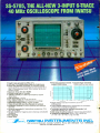
TEK DUAL TRACE OSCILLOSCOPES
Now! Tek quality and expert advice
are just a free phone call away!
The industry
standard in CRT
performance.
Crisp, easy-toread, bright CRT;
14kV accelerating
potential, provides
high writing rate
and small spot
size. Full size 8x10
cm display for
measurement
accuracy.
Display controls
are flexible and
easy to use. Separate intensity
controls reduce
blooming in alternate sweep mode.
Focus tracking
minimizes control
adjustment and
BEAM FIND eliminates confusion.
Our direct order line gets
you the industry's leading
price/performance portables...
and fast answers from experts!
The 60 MHz single time base delay
2213A, the 60 MHz dual time base
2215A and the 100 MHz dual time
base 2235 offer unprecedented
reliability and affordability, plus the
industry's first 3 -year warranty*
on labor and parts, CRT included.
The cost: just $1275 for the
2213A, $1525 for the 2215A,
$1750 for the 2235.t Even at
these low prices, there's no
scrimping on performance. You
Vertical system provides
measurement
assurance. Flat
transient response
and high accuracy
ensures true
reproduction of
your signals. Fast
risetime and high
bandwidth is well
suited for a variety
of measurement.
Perform delayed
sweep measurements accurately
and easily. Both
sweeps can be
displayed alternately making differential measurements easy and
accurate (1 %).
An interlocking
SEC /DIV control
simplifies set -up.
have the bandwidth for digital
and analog circuits. The sensitivity
for low signal measurements. The
sweep speeds for fast logic families. And delayed sweep for fast,
accurate timing measurements.
All scopes are UL Listed and CSA
approved.
You can order, or obtain
literature, through the Tek
National Marketing Center. Technical personnel, expert in scope
applications, will answer your
questions and expedite delivery.
Direct orders include comprehensive 3 -year warranty *, operator's
Stable hands -off
triggering. P -P
AUTO detects signal peaks, then
sets the trigger
Front panel laid
out by function
for ease of use.
Color coding aids
the user in opera-
play asynchronous
signals using
tion. Functions
and modes are
placed logically.
All nomenclature
VERT MODE trig-
is clearly labeled,
gering. Independent TV field and
line selection.
and protected
level for you. Dis-
behind a scratchless Lexan surface.
manual, two 10X probes, 15 -day
return policy and worldwide service backup.
Order toll free:
1- 800 -426 -2200,
Ask for Rick.
In Oregon, call collect:
(503) 627 -9000.
Or write Tektronix, Inc.
P.O. Box 1700
Beaverton, OR 97075
TéJctronbc
COMMITTEE) TO E%CELLHW
Copyright ®1985, Tektronix, Inc. All rights reserved. STTA- 439 -3. tPrice F.O.B. Beaverton, OR. `3 -year warranty includes CRT.
If
MAKEj
i
Do You REALLY Want to Make More Money?
Yes it does take work and a few sacrifices to
climb up the electronics ladder to where the bigger
money is. But, if that's where you want to be, then
that's what you must do
work harder at learning
and getting the right credentials, even if it takes a
few sacrifices. A B. S. degree and the knowledge
that rightly goes along with it can give you powerful
ladder-climbing equipment in your search for success in electronics.
The accredited Grantham non -traditional B.S.
Degree Program is intended for mature, fully employed workers who want to upgrade their electronics careers.
-
ELECTRONICS
Put Professional Knowledge and a
You say you're already trained in electronics
but that you're not making enough money ???
Well then, maybe you don't have an accredited
bachelor's degree to prove that your education
is up to snuff. Check out the Grantham Independent -Study B. S. Degree Program. It could
make a dollars and sense difference in your
electronics career.
Grantham offers this program, complete but
without laboratory, to electronics technicians
whose objectives are to upgrade their level of
technical employment. Since the field of electronics is so enormous, opportunity for advancement is always present. Promotions and
natural turnover make desirable positions
available to the man who is ready to move up.
COLLEGE DEGREE
in your Electronics Career through
Independent Home Study
Study materials, carefully written by the Grantham
College staff for independent study at home, are
supplied by the College. Your technical questions
related to these materials and the lesson tests are
promptly answered by the Grantham home -study
teaching staff.
Recognition and Quality Assurance
Grantham College of Engineering is accredited by
the Accrediting Commission of the National Home
Study Council, as a degree -granting institution.
Grantham College of Engineering
10570 Humbolt Street
Los Alamitos, California, 90720
All lessons and other study materials, as well as cornmunications between the college and students, are in the
English language. However, we have students in many
foreign countries; about 80% of our students live in the
United States of America.
for
FREE
Please mail me your free catalog which explains your
B.S. Degree independent -study program.
CLIP
COUPON
and mail in
envelope or
paste on
postal
card.
1
10570 Humbolt Street, Los Alamitos, CA 90720
Booklet
This free booklet
explains the
Grantham B.S.
Degree Program,
offered by independent study to
those who work
in electronics.
M-9-85
Grantham College of Engineering
J
Name
Age
Address
L
City
State
September 1985
/
Zip
MODERN ELECTRONICS /
I
NEW:
uniden®
ßontir-Aat
NEW!
JIL SX -400 -J
List price $799.95/CE price $489.00 /SPECIAL
NEW! Bearcat® 800XLT-J
Frequency range: 26-520 MHz continuous coverage.
With optionally equipped RF converters 150KHz. -3.7 GHz.
The JIL SX -400 synthesized scanner is designed for
commercial and professional monitor users that demand features not found in ordianary scanners. The SX400 will cover from 150 KHz to 3.7 GHz. with RF
converters. Order the following RF converters for your
SX -400 scanner. RF-1030 -J at $259.00 each for
frequency range 150 KHz. -30 MHz. USB, LSB, CW and
AM. (CW filter required for CW signal reception); RF5080-J at $199.00 each for 500-800 MHz.; RF-8014 -J
at $199.00 each for 800 MHz.-1.4 GHz. Be sure to
also order ACB-300 -J at $99.00 each which is an
antenna control box for connection of the RF converters.
Add $3.00 shipping for each RF converter or antenna
control box. If you need further information on the JIL
Bands: 29 -54, 118-174, 406 -512, 806-912 MHz
The Uniden 800XLT receives 40 channels in two banks.
Scans 15 channels per second. Size 91/4' x4'/2" x 12 %."
Multi-Band, 20 Channel No-crystal S
Search Lockout Priority AC/DC
scanners, contact JIL directly at 213-926-6727 or write
JIL at 17120 Edwards Road, Cerritos, California 90701.
Scanners
Communications Electronics;
the world's largest distributor of radio
scanners, introduces new scanners
and scanner accessories from J.I.L.,
Regency and also Uniden /Bearcat.
Chances are the police, fire and
weather emergencies you'll read
about in tomorrow's paper are coming
through on a scanner today.
NEW! Regencyl MX7000 -J
List price $699.95/CE price $424.00 /SPECIAL
10 -Band, 20 Channel Crystalises AC/DC
Frequencyrange: 25 -550 MHz continuous coverage
and 800 MHz. to 1.3 GHz continuous coverage
In addition to normal scanner listening, the
MX7000 offers CB, VHF, and UHFTVaudio, FM
Broadcast, all aircraft bands (civil and military),
800 MHz communications, cellular telephone,
and when connected to a printer orCRT, satellite
weather pictures. If you just need continuous
frequency coverage of 25 -550 MHz. order the
Regency MX5000 -J for only $329.00 each.
NEW! Regency° MX4000 -J
List price $629.95/CE price $299.00 /SPECIAL
Multi-Band, 20 Channel No-crystal scanner
Search Lockout Priority AC /DC
Selectable AM-FM modes LCD display
Bands: 30 -50, 118.136, 144- 174, 440. 512, 800 -950 MHz.
The Regency MX4000 is gives coverage in the
standard VHF and UHF ranges with the important addition of the800 MHz. and aircraft bands.
It features keyboard entry, multifunction liquid
crystal display and variable search increments.
NEW! Regency° Z60 -J
List price $379.95/CE price $216.00 /SPECIAL
8-Band, 60 Channel No-crystal scanner
Bands: 30 -50, 88 -108, 118.136, 144 -174, 440 -512 MHz.
Cover your choice of over 15,000 frequencies
on 60 channels at the touch of your finger.
Regency° HX- 650P-J
List price $189.95/CE price 499.00 /SPECIAL
5 -Band, B Channel Handheld crystal scanner
Bands: 30-50, 146 -174, 450-512 MHz
Now, Communications Electronics Inc. offers a
special package price on the Regency HX -650
scanner and the following items for only$94.00.
You get the Regency H X-650 scanner, a set of 4
AAA ni- cadbatteries, the MA-506 carrying case,
six crystal certificates, AC adapter/charger and
flexible rubber antenna for only $99.00 per
package plus $10.00 shipping /handling.
SX -200-J
SPECIAL! JIL
special price
List price $499.95/CE
Multi-Band -18 Channel
$159.00
No-CrystalScanner
Frequency range 26-88, 108.180, 380 -514 MHz
The JIL SX -200 scanner tunes military, F.B.I., Space
Satellites, Police and Fire, Drug Enforcement Agencies,
Defense Department, Aeronautical AM band, Aero
Navigation Band, Fish & Game, Immigration, Paramedics,
Amateur Radio, Justice Department, State Department,
plus other thousands of radio frequencies most other
scanners can't pick up. The SX -200 has selectable
AM /FM receiver circuits, tri-switch squelch settings signal, audio and signal & audio, outboard AC power
supply - DC at 12 volts built -in, quartz clock - bright
vacuum fluorescent blue readouts and dimmer, dual
level search speeds, tri -level scan delay switches, 16
memory channels in two channels banks, receive fine
tune (RIT) ± 2KHz., dual level RF gain settings- 20 db
pad, AGC test points for optional signal strength meters.
All in all, the JIL SX-200 gives you more features for the
money than any other scanner currently on sale. Order
your JIL SX -200 scanner at this special price today.
Regency® HX1000 -J
List price $329.95/CE price $209.00
No Crystal scanner
6 -Band, 30 Channel
Scan delay
Lockout Priority
Search
Sldelit liquid crystal display
Digital Clock
Frequency range: 30 -50, 144 -174, 440 -512 MHz.
The new handheld Regency HX1000 scanner is fully
keyboard programmable forthe ultimate in versatility. You can scan up to 30 channels at the same time.
When you activate the priority control, you automatically override all other calls to listen to your favorite
frequency. The LCD display is even sidelit for night
use. Order MA -258 -J rapid charge drop-in battery
charger for $79.00 plus $3.00 shipping /handling.
Includes wall charger, carrying case, belt clip,
flexible antenna and nicad battery. Order now.
NEW! Bearcat° 100XL -J
List price $349.95 /CE price $229.00
Priority Scan Delay
9-Band, 16 Channel
Limit Hold Lockout AC/DC
Search
Frequency range: 30-50, 118 -174, 406-512 MHz
The world's first no-crystal handheld scanner now has
a LCD channel display with backlight for low light use
and aircraft band coverage at the same low price. Size is
1%" x 7'/2" x 27/8!' The Bearcat 100 XL has wide frequency
coverage that includes all public service bands (Low,
High, UHF and "T' bands), the AM aircraft band, the 2meter and 70 cm. amateur bands, plus military and
federal government frequencies. Wow...what a scanner!
Included in our low CE price is a sturdy carrying case,
earphone, battery charger /AC adapter, six AA ni -cad
batteries and flexible antenna. Order your scanner now.
NEW! Regency® HX2000 -J
The World's First800 MHz. Handheld Scanner
List price $569.95/CE price $299.00/SPECIAL
No- crystal scanner
7 -Band, 20 Channel
Priority control Search/Scan AC/DC
indent liquid crystal display Memory backup
Bands: 118 -136, 144 -174, 440-512, 800-950 MHz.
The HX2000 scanner operates on 120V AC or 6 VDC.
Scans 15 channels per second. Size 3" x 7" x 1'/2."
Includes wall charger, carrying case, belt clip, flexible
antenna and nicad batteries. Selectable AM/FM modes.
Regency
RH250
List price $499.95/CE price $329.00
No- crystal scanner
12 -Band, 40 Channel
Priority control Search/Scan AC/DC
OTHER RADIOS AND ACCESSORIES
Panasonic RF- 2800 -J Shortwave receiver
$179.00
$195.00
Panasonic RF- B300 -J Shortwave receiver
RD95 -J Uniden Remote mount Radar Detector
5139.00
$344.00
BC 300-J Bearcat 50 channel scanner
BC 20/20-J Bearcat 40 channel scanner
$274.00
$219.00
BC 210XW -J Bearcat 20 channel scanner
BC 280 -J Bearcat 16 channel mobile scanner ... $274.00
$189.00
BC 201 -J Bearcat 16 channel scanner
BC 180 -J Bearcat 16 channel scanner
$184.00
$39.00
BC -WA -J Bearcat Weather Alert"
$459.00
DX 1000 -J Bearcat shortwave receiver
$99.00
PC22-J Uniden remote mount CB transceiver
$59.00
PC55 -J Uniden mobile mount CB transceiver
10
210 -J Regency
channel scanner
$139.00
Z30 -J Regency 30 channel scanner
$154.00
$179.00
245 -J Regency 45 channel scanner
MX3000 -J Regency 30 channel scanner
$189.00
0403 -J Regency 4 channel scanner
$69.00
R106 -J Regency 10 channel scanner
$99.00
RH250 B-J Regency 1 o channel VHF transceiver ... $329.00
RU15GB-J Regency 10 channel UHF transceiver ... $449.00
RPH410-J 10 ch. handheld no-crystal transceever ... $399.00
BC10 -J Battery charger for Regency RPH410
$79.00
MA258 -J Drop-in charger for 1-1X1000 scanner .... $79.95
MA257 -J Cigarette lighter cord for HX1000
$19.95
MA258 -J Ni -Cad battery pack for HX1000
$24.95
EC1 O-J Programming tool for Regency RPH410... $20.00
SMRH250-J Service man. for Regency RH250.... $20.00
SMRU150-J Service man. for Regency RU150 .... $20.00
SM R PH410 -J Service man. for Regency RPH410 ... $20.00
B-4 -J 1.2 V AAA Ni -Cad batteries (set of four)
$9.00
A- 135C -J Crystal certificate
$3.00
FB-E -J Frequency Directory for Eastern U.S.A .... $12.00
FB-W-J Frequency Directory for Western U.S.A.... $12.00
TSG -J "Top Secret" Registry of U.S. Govt. Freq.... $15.00
TIC -J Techniques for Intercepting Comm.
$15.00
RRF -J Railroad frequency directory
$10.00
$15.00
CIE -J Covert Intelligenct, Elect. Eavesdropping
A60-J Magnet mount mobile scanner antenna
$35.00
A70 -J Base station scanner antenna
$35.00
USAMM -J Mag mountVHF /UHFant. w/ 12' cable... $39.95
USAK -J'/:' hole mountVHF /UHFant. w/ 17' cable ... $35.95
USATLM-J Trunk lip mount VHF /UHF antenna .... $35.95
.
Add $3.00 shipping for all accessories ordered at the same time.
Add $12.00 shipping per shortwave receiver.
Add $7.00 shipping per scanner and $3.00 per antenna.
BUY WITH CONFIDENCE
get the fastest delivery from CE of any scanner,
send or phone your order directly to our Scanner
Scanner Distribution Center' Michigan residents please
add 4% sales tax or supply your tax I.D. number. Written
purchase orders are accepted from approved government agencies and most well rated firms at a 10%
surcharge for net 10 billing. All sales are subject to
availability, acceptance and verification. All sales on
accessories are final. Prices, terms and specifications
are subject to change without notice. All prices are in
U.S. dollars. Out of stock items will be placed on backTo
order automatically unless CE is instructed differently.
A $5.00 additional handling fee will be charged for all
orders with a merchandise total under $50.00. Shipments are F.O. B. Ann Arbor, Michigan. No COD's. Most
products that we sell have a manufacturer's warranty.
Free copies of warranties on these products are available prior to purchase by writing to CE. Non -certified
checks require bank clearance.
Mall orders to: Communications ElectronBox 1045, Ann Arbor, Michigan 48106
U.S.A. Add $7.00 per scanner for U.P.S. ground
shipping and handling in the continental U.S.A.
For Canada, Puerto Rico, Hawaii, Alaska, or
APO /FPO delivery, shipping charges are three
times continental U.S. rates. If you have a Visa
or Master Card, you may call and place a credit
card order. Order toll-free in the U.S. Dial
800 -USA -SCAN. In Canada, order toll-free by
calling 800 -221 -3475. WUI Telex CE anytime,
dial 671 -0155. If you are outside the U.S. or in
Michigan dial 313- 973 -8888. Order today.
ics',"
Scanner Distribution Center"' and CE logos are trademarks of Communications Electronics Inc.
t
Bearcat is a registered trademark of Uniden Corporation.
:Regency is a federally registered trademark of Regency
AD *081185 -J
Electronics Inc.
Copyright a 1985 Communications Electronics
For credit card orders call
1- 800 - USA-SCAN
TM
//COMMUNICATIONS
ELECTRONICS INC.
Consumer Products Division
-1045 U.S.A.
MX4000
HX2000
Ann Arbor, Michigan48106
Ca11800- USA-SCAN or outside U.S.A. 313- 973.8888
P.O. Box 1045
MX7000
CIRCLE 82 ON READER SERVICE CARD
FIEll/amomtimcs
EDITORIAL STAFF
Art Salsberg
Editor -in -Chief
Alexander W. Burawa
Managing Editor
THE MAGAZINE FOR ELECTRONICS & COMPUTER ENTHUSIASTS
Dorothy Kehrwieder
Production Manager
VOLUME 2, NUMBER 3
SEPTEMBER 1985
Elizabeth Ryan
Art Director
22
FEATURES
Barbara Scully
Audio and Video In Your Future
Pat Le Blanc
Artist
...
Richard Kishanuk
As foretold at the 1985 Summer CES.
By Len Feldman
28
Phototypographers
Hal Keith
Illustrator
Larry Mulvehill
Photographer
Dress Up Your Projects
An easy photo technique for making commercial quality front panels. By C.R. Ball
36
Simple Tunes on Your Apple IIc
How to program a IIc to play musical tunes.
By Fred Blechman
42
22
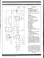
Designing With Switching Regulators
Power supplies with increased efficiency and
reduced size. By Anthony J. Caristi
48
Leonard Feldman, Glenn Hauser,
Don Lancaster, Forrest Mims III,
Stan Prentiss, Charles Rubenstein
Contributing Editors
BUSINESS STAFF
Richard A. Ross
Store Soft: A 16-bit Logic Analyzer
Publisher
Test instrument project simplifies and speeds
Art Salsberg
troubleshooting of computers and other
digital systems. By Desmond Stelling
53
Associate Publisher
Dorothy Kehrwieder
A Simple Cable Communications System
General Manager
Transmit analog and digital signals over long
distances with this home -brewed system.
By Duane M. Perkins
59
64
36
Anthony C. Sparacino
Newsstand Sales Director
Connector Replacement Service Tips
Arlene Caggiano
How to remove damaged connectors without
damaging pc boards.
Cheryl Chomicki
Using the Experimenter's Interface
Device
SALES OFFICES
Experimenting with I/O lines on a C -64 computer.
By Dovell M. Bonnett & Kendra R. Bonnett
Accounting
Subscriber Services
Modern Electronics
76 North Broadway
Hicksville, NY 11801
(516) 681-2922
PRODUCT EVALUATIONS
12
Magnavox Portable VHS VCR System
-
Stereo Hi-Fi in a small package. By Stan Prentiss
tr.foss*
15
RS -232 Switches
Litek HackerSwitch 2; Tigertronics Model S -8
RS232 Switch; IQ Industries Smart Cable.
By Fred Blechman
48
DEPARTMENTS
4
--
.mik..
1
..
i
Editorial
By Art Salsberg
4
5
6
61
69
Letters
Modern Electronics News
New Products
Free Information Service
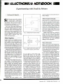
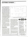
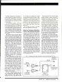
Electronics Notebook
Experimenting With Small dc Motors.
By Forrest M. Mims III
74
Hardware Hacker
Understanding Shaft Encoders and more.
By Don Lancaster
78
¡
//7/
\
\\\'''.:N41*
_
(212) 490-1021
Midwest Advertising Representative
Market /Media Associates
435 Locust Road
Wilmette, IL 60091
(312) 251 -2541
E
28
Eastern Advertising Representative
Paul McGinnis Company
60 East 42nd Street
New York, NY 10017
Work
.
surface
Software Focus
Inside the IBM PC With Programming
Access Tools. By Charles Rubeinstein
80
85
100
Communications
Combatting the Russian Woodpecker.
By Glenn Hauser
Books & Literature
Advertisers Index
Ted Rickard
Western Advertising Representative
JE Publishers Representatives
6855 Santa Monica Blvd., Suite 200
Los Angeles, CA 90038
(213) 467 -2266
Jay Eisenberg, Director
San Francisco: (415) 864 -3252
Denver: (303) 595 -4331
Offices: 76 North Broadway, Hicksville, NY 1801. Te
ephone: (516) 681 -2922. Modern Electronics (ISSN 07489889) is published monthly by Modern Electronics, Inc.
Application to mail at second class rates pending at
Hicksville, NY and other points. Subscription prices
(payable in US Dollars only): Domestic - one year S 16.97,
two years $31.00. three years 145.00; Canada /Mexico
-one year 519.00, two years $35.00. three years 551.00;
Foreign - one year 521.00, two years 539.00. three years
557.00. Foreign Air Mail - one year S74.00, two years
1
5145.00, three years S216.00.
Entire contents copyright 1985 by Modern Electronics,
Inc. Modern Electronics or Modern Electronics, Inc. assumes no responsibility for unsolicited manuscripts. Allow six weeks for delivery of first issue and for change of
address. Printed in the United States of America.
Postmaster: Please send change of address notice to
Modern Electronics, Inc., 76 North Broadway. Hicksville, NY 11801.
September 1985
/
MODERN ELECTRONICS
/
3
llih/EDITORIA L Ill/Ill
Leapfrogging
Manufacturers are constantly refining
their electronic products: an extra output
here, a slightly improved video resolution
there, a doubling of chip memory, etc.
From time to time, however, there's a
quantum jump to a new technological
plane. We've witnessed this many times:
from transistor to integrated circuit,
from monophonic sound to stereo, from
analog records to digital laser-read discs,
and so on. There's lots more churning in
the developmental stage right now that
can come to fruition sooner than one
might think.
For example, lots of people dream
about living in a "smart" house, with all
manner of electronic contrivances for
them to control. A few individuals have
indeed created such homes. Now, however, there are some thrusts being made to
eventually spread this concept as a reality
to a great many people.
Eighteen companies are involved in
Smart House Development Venture Inc.
to do just this. They include Apple Computer, General Electric, and Honeywell,
with support from 130,000- member
NAHB (National Association of Home
Builders).
The basic approach to the "smart"
house is to replace our standard 120 Vac
electric circuits with an integrated power
and signal bus line. This would enable the
integration of entertainment equipment,
security systems, computers, energy management, telephone gear, etc. Key to this
system concept is a microprocessor -based
system controller, which would control
power or signal demands from whatever a
plugged -in device calls for. A new, single
plug would have to be used and the National Electrical Code would have to be
changed to allow its use.
Honeywell is already a step ahead here
with a hotel-office complex that's to be a
"smart" building that provides computer
services, advanced communications systems, etc. All this is said to cost a 15 -employee tenant about $1,000 per month or
only half as much more as one would pay
for a phone system. It's called the Renaissance Center, in Fairfax County, VA.
In about two years, the NAHB expects
a smart -house system to be installed in
1'h-million new homes every year. I'm
saving my pennies for it right now.
There have been plenty of bummers, of
course. Developments that are still waiting on the sidelines, held back for a variety of reasons. Such very promising concepts include Videotex -information services at your beck and call through your
home TV set. Electronic banking, shopping, and so on. It's (very) slowly growing, but nowhere near being a big market
...yet.
High -definition TV was supposed to be
right around the corner, too. Our skylines
were envisioned to be broken up by direct- broadcast satellite dishes on rooftops around the country, while cable -TV
was to be relegated to interactive applications. It hasn't happened ... yet. Nor has
optical computers made the grade. Ver-
batim, though, recently revealed a 40megabyte disk drive that uses erasable optical disks. And AT &T is furiously working away in its Bell Labs on optically sensitive gallium- arsenide devices. So who
knows?
Whatever happens down the road, however, you can be certain that more power
will be packed on chips. So just as the
256K -bit IC with its 2- micron circuit size
made it possible to produce much more
powerful microcomputers, so will the
1- micron chip with its 1-Megabit power
that's soon expected to debut give us
powerful pocket computers, among other small -size electronic products that can
do marvelous things. And before you
know it, in about a decade, you can expect chips with 4-million transistor equivalents on it. This 4- megabit, '/ -micronsize device will open up the world of artificial intelligence to small devices, say,
personal home robots that can "think"
logically, place supercomputers that now
cost many millions of dollars on our desks
for only hundreds of dollars, etc.
So we've got a lot of fun happenings to
look forward to, even if some exciting
concepts do fall through the cracks.
There'll still be plenty of revolutionary
leapfrogging of technology that we electronics activists will be able to savor.
Ui/il/LETTERS/Ill/il
Designing For Safety
"An Experimenter's Multi- Voltage
Power Supply" (May 1985) was a good
construction article but it was marred by a
potentially dangerous design flaw. It
doesn't incorporate a three-wire safety ac
line cord, and its fuse should be located
before -not after -the power switch.
Good design practice calls for using the
three -wire ac line cord in any project
housed inside a metal cabinet. The white
and black wires would go to the power
supply's ac input terminals, while the
green wire would connect directly to chassis
/
tronics. The issues I got mention an article in the January 1985 issue about the
"Digital Humidity Controller." I have a
great need for such a piece of equipment.
How can I either secure a copy of the January issue or a copy of the article?
G. Baldauf
Wernersville, PA
Send $2.50 for the issue to Modern Electronics, 76 North Broadway, Hicksville
I1801.-Ed.
Extra Credit
ground.
Richard Jon Jansma
Raleigh, NC
4
Back Issues
I'm a new subscriber to Modern Elec-
MODERN ELECTRONICS
/
Since your first issue in October of '84 I
have been an avid reader of your publica-
September 1985
tion and have been enthusiastically recommending it to my students at Suburban Technical School, Hempstead, NY. I
also offer extra credit for building any of
the many projects you often publish in
your magazine because it enables them to
apply their training in computers and
electronic communications technology
while building useful circuitry.
M.E. truly offers something for all, be
you a novice or an advanced student of
electronics. Personally, I most enjoyed
the article by Stan Prentiss on satellite TV
(December '84).
Kevin Coppola
Suburban Technical School
Hempstead, NY
!IIIIMODERN ELECTRONICS NEWS/I/fill
SATELLITE TV RECORD SETTER. The R.L. Drake Company claims it has sold
more than 270,000 TV earth station receivers, a remarkable milestone
when you consider that the entire satellite TV industry sales hardly
exceed one -million receiver units.
ELECTRONIC ENGINEER SALARIES UP. EE's are doing quite well, thank you,
according to a recent IEEE report that the national median salary was
$46,100 in 1984, an increase of 15% compared to 1983.
Top pay area
was San Francisco, with $53,000, followed by metropolitan New York City
with $51,500. Starting salaries in the New York area are now said to
be $24,852 to $28,404 for EE's with Bachelor's degrees.
The top starting wage is reportedly about $2,000 under the national average, though.
Sorry, Liberal Arts people.
TALK, TALK, TALK. A 1,000 -word speech recognizer was announced by
Kurzweill Applied Intelligence. Called the KVS -3000 system, it compares
spoken input with 3,0000 speech tokens, which may be expanded by more
memory boards to up to 15,000 tokens and 5,000 -word recognition.
It's
yours for $6,000, which includes an RS -232 interface, in a self -contained
desktop package.
On another talk front, Motorola has introduced a "convertible"
cellular phone that's designed for hand -held portable use as well as
for in- vehicle mobile applications.
It incorporates automatic tone alerting for signalling incoming call attempts in marginal- coverage areas.
$2850 (with case, shoulder strap and belt clip).
COMPUTER SECURITY. Software publisher BrainPower "unprotected" all its
software recently.
The company concluded that copy protection only
limits product use and makes it harder for users to protect themselves
against media failures.
On the other side, Arnet Controls of Nashville,
TN introduced a new device, called Gardware, to fight software piracy
and unauthorized computer access.
It's a little black box that must be
plugged into the computer before software can be used.
It works with the
IBM PC and Apple Macintosh.
VCR -COMPANY SHAKEOUT COMING? Videocassette recorders have been selling
at record paces this year, causing the EIA to revise its 1985 sales forecast upward to 11.5- million units, which compares very favorably to the
7.6- million sold in 1984.
Nonetheless, there are some worries because
there are some reported 15 to 16 million that could reach our shores
from the Far East in total.
U.S. warehouses are said to have an inventory backup at this time. So even though the VCR star shines bright,
with a projected 12- million units for 1986, manufacturers are getting
scared.
With 68 brands out there vying for your money, it's felt that
some will bite the dust soon.
AUDIO RECORDING IN A PEN. A microminiature pen in a holder is actually
a miniature cassette tape recorder for on -the -sly voice recording.
From
CCS Communication Control, New York City, the recorder systems fits into
a breast pocket and is activated when a black Cross pen is removed.
September 1985
/
MODERN ELECTRONICS
/
5
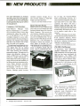
11111111/NEW
PRODUCTS Nllld
For more information on products
described, please circle the appropriate number on the Free Information
Card bound into this issue or write to
the manufacturer.
Computer / VCR Interface
Video -Memory
Manager
from
Kirsch Technologies is a software driven hardware plug -in board that
inexpensively allows any Apple II,
II + or IIe, IBM PC or XT, or true
workalike computer to use a videocassette recorder for mass storage. It
operates with standard video signals
that allows any- format VCR or laser
disc to be used in this manner.
The hardware board plugs into any
open slot in the computer and converts digital data into an analog
signal for easy operator interaction
with video pictures and software generated prompts. Through use of a
unique error -detection scheme, as
much as 96M bytes can be reliably
stored on a single videocassette. A
Video -Data Filer utility program on
floppy disk provides the capability of
backing up and restoring memory between floppy diskettes, hard -disk
systems and video tape. The assembly- language software is menu driven. With it, not only does Video Memory Manager greatly increase
computer memory storage, but it
also provides backup of hard -disk
images and individual files.
CIRCLE NO. 128 ON FREE INFORMATION CARD
Home Security Device
Home security is just a telephone call
away with the new Model GD -1702
Vacation /Home Sentry kit from the
Heath Company. This security device monitors internal house conditions and relays the information to
you over the telephone line. As supplied, the GD -1702 detects low temperatures, but it can optionally be
equipped to detect the presence of
water, lights, an intruder, etc. with
appropriate sensors connected to it.
In operation, a vacationing home
owner or neighbor simply calls the
house. After a predetermined num-
ber of rings, the Vacation /Home
Sentry automatically activates. If a
sensor has been tripped by a temperature below 40 °F or by some other
condition, the Sentry will emit a
beeping signal through the telephone. If conditions are normal, you
will hear nothing and the Sentry will
automatically disconnect and return
to its monitor mode after a few
seconds.
The GD-1702 plugs into any modular phone line and is powered by two
9 -volt transistor batteries. Power
from the batteries is drawn only when
the device is relaying information in
response to a phone query.
CIRCLE NO. 129 ON FREE INFORMATION CARD
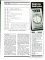
150-MHz Oscilloscope
A quad- input, dual independent
timebase oscilloscope with a 150 MHz bandwidth for both bench and
field use has been introduced by
The Model 1596
scope offers ±2% vertical accuracy
and features 500 -µV /division sensitivity to 70 MHz (cascade channel 1
to channel 2), 1 mV /division to 100
MHz, and 5 mV/division to 150
B &K- Precision.
MHz. Waveforms are displayed on
an 8 x 10- division (one division =1
cm) rectangular CRT with internal
graticule, scale illumination and
20 -kV acceleration voltage.
In addition to standard A only,
ALT, A- INT -B, B DLY'D sweep op-
6
/ MODERN ELECTRONICS / September 1985
eration, the scope features Dual
mode in which A and B sweeps operate independently of each other.
Two signals can be viewed in different sweep times in the Dual mode.
Trigger modes include AUTO,
NORM and Single Sweep operation.
Other features include 20 ns /division
sweep speed (2 ns /division with x 10
magnification); 20 -MHz bandwidth
limiter to eliminate high- frequency
noises when viewing low- frequency
signals; video sync circuitry for viewing video signals; channel -1 output to
which a frequency counter or other
peripheral device can be connected;
and a beam finder. Functions are selected by LED -lighted, microprocessor-controlled pushbutton switches.
Weight is 16.3 lbs. $2905.
CIRCLE NO. 130 ON FREE INFORMATION CARD
Audio /Video Hi -Fi Amplifier
Technics' new Model SU -V 10X integrated stereo amplifier has been designed to meet the needs of modern
digital audio and hi -fi video. Its
constant -gain predriver, along with
Computer Drive class -A circuitry
and a power linear circuit, have been
designed from the ground up, says
the manufacturer. To avoid possible
signal interference between sight and
sound, the amplifier has separate
audio and video circuit paths. In addition, two separate record selectors
allow you to listen to the phono
source while recording from another
program source.
A total of seven audio inputs
(phono, tuner, CD, TV /AUX 1,
video /AUX 2, tape 1 /DA tape, and
tape 2 /VTR) can be handled by the
Model SU -V 1 OX. The three video
inputs, of course, are TV /AUX 1,
video AUX2 and tape 2 /VTR. With
the video inputs, you get simultaneous audio /video signal switching capability. With video /AUX 2, there
are sets of jacks on both the front and
rear panels, allowing you to select
one or the other for video dubbing
and quick hookup of a portable deck.
Other features include: low -noise
FET MM /MC phono equalizer; turnover frequency selectors for the tone
controls; external jacks for connection of a graphic equalizer or other
accessory; subsonic filter; audio muting; tone -defeat switch; and a main
and /or remote speaker selector.
Output power from the amplifier
is rated at 120 watts /channel continuous rms into 8 ohms from 20 Hz
to 20 kHz at no more than 0.003 Wo
THD. $600.
CIRCLE NO.
131 ON
FREE INFORMATION CARD
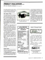
Bubble -Jet Matrix Printer
High -speed low -noise printing are
offered by Canon USA's new Model
BJ-80 nonimpact Bubble -Jet Printer.
The 80- character -per -line printer
uses a 9 x 24- matrix printhead to
hammer out copy at a speed of 220
cps in draft mode, while operating at
a noise level of less than 45 dB. In the
near -letter -quality mode, the printer
shifts to an 18 x 24- matrix printhead
format to produce high- density copy
at a speed of 110 cps.
The compact, lightweight printer
compatible with the IBM PC and
PC- compatible computers. It provides high- density graphics printing
in addition to its condensed, enlarged
is
and superscript /subscript character
set. International character sets are
optionally available. The printer uses
black ink -jet cartridges and can accommodate both continuous fanfold and single -sheet paper. $599.
CIRCLE NO. 132 ON FREE INFORMATION CARD
Surface -Mount Test Clip
A P Products has introduced a new
surface -mount test clip that addresses the problems of other such
fixtures for testing plastic leaded chip
carrier (PLCC) ICs. The 20 -conductor size test clip features an innovative action wedge design that enables all four sides of the test clip to
open simultaneously to provide saf(Continued on page 86)
September 1985
/
MODERN ELECTRONICS
/
7
Train For the Fastest Growing Job Skill in America
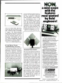
Only NRI teaches you
to service and repair
all computers as you
build your own 16-bit
IBM-compatible micro
As computers move into
offices and homes by the millions,
the demand for trained computer
service technicians surges forward.
The Department of Labor estimates
that computer service jobs will
actually double in the next ten
faster growth than any
years
New from NRI -the only home study course that
trains you as you assemble a top-brand computer!
-a
other occupation.
Total System Training
As an NRI student, you'll get
total hands-on training as you
actually build your own Sanyo
MBC-550 -2 computer from the
keyboard up. Only a person who
knows all the underlying fundamentals can cope with all the
significant brands of computers.
And as an NRI graduate, you'll
possess the up- to-the- minute
combination of theory and practical
experience that will lead you to
success on the job.
You learn at your own convenience, in your own home, at
your own comfortable pace. Without classroom pressures, without
rigid night -school schedules,
without wasted time. Your own
personal NRI instructor and NRI's
complete technical staff will
answer your questions, give you
After you construct this
digital logic probe, you'll
install the "intelligent"
Sanyo detached keyboard,
with its dedicated
microprocessor.
You next assemble the
power supply into the
main unit of the computer.
Using the digital multi meter, you check all
keyboard connections
and circuits.
guidance and special help whenever
you may need it.
The Exciting Sanyo MBC-
550-2 -Yours To Keep
Critics hail the new Sanyo as
the "most intriguing" of all the
IBM-PC compatible computers. It
uses the same 8088 microprocessor
as the IBM -PC and the MS /DOS
operating system. So, you'll be able
to choose thousands of off-the -shelf
software programs to run on your
completed Sanyo.
After you install the disk
drive and monitor, you'll
make a backup copy of the
MS -DOS operating disk,
explore the 8088 microchip
and additional circuits.
As you build the Sanyo from
the keyboard up, you'll perform
demonstrations and experiments
that will give you a total mastery of
computer operations and servicing
techniques. You'll do programming
in BASIC language. You'll prepare
interfaces for peripherals such as
printers and joysticks. Using utility
programs, you'll check out 8088
functioning. NRI's easy step -by -step
instructions will guide you all the
way right into one of today's fastest
growing fields as a computer
service technician. And the entire
system, including all he bundled
software and extensi e data
manuals, is yours to keep as pal
of your training.
How the pro computer
critics rate the
Sanyo 550:
'Sanyo BASIC is definitely
superior to IBM Microsoft... lets
you use two or three keystrokes for
entering BASIC commands."
-MICROCOMPUTING Magazine
"... compares favorably with
the IBM PC, even surpassing it in
computational speed... "
-COMPUTERS
&
ELECTRONICS Magazine
cu
NRI Ccurse Includes a Sanyo MBC650 Comp_ ter with 128K RAM, Monitor,
Disk Drive, aid "Intelligent" Keyboard;
a WRI Dist overy Lab Teaching Circuit
Desi in and Operations; a Digital
N itt meter; Bundled Spread Sheet and
Word Processing Software Worth $1500
at Retail -and More.
,
7 went to have a look at the
MBC-550... what I found made
me an owner the next day!"
Communications, TV /Video/
Audio Servicing, and other growing high-tech career fields. If the
card is missing write to NRI at the
address below.
-Bill Sudbrink,
BYTE Magazine
100 -Page Free Catalog
Teils More
Send the postage -paid reply
card today for NRI's big 100 -page
color catalog, which gives you all
the facts about NRI training in
Microcomputers, Robotics, Data
MKC
H OC
LS
McGraw-Hill Continuing Education Center
3939 Wisconsin Avenue, NW
Washington, DC 20016
RYA
We'll Give You Tomorrow.
1:111
IBM is a Registered Trademark of International
Business Machine Corporation.
,
ill
11111111
PRODUCT EVALUATIONS
111111
Video
Magnavox Portable VCR System:
Stereo Hi -Fi in a Small Package
Like some other companies in the onrushing videocassette recorder industry, Magnavox is also featuring a two -piece cornpact VHS portable that's equally at home
for lightweight camera recording or
stacked as an integrated unit for off-theair recording or simple playback. Foremost among its many features is its ability
to record and play back audio with high fidelity quality, in either monophonic or
stereo modes. Moreover, it uses standard -size video cassettes, permitting as
much as 8 hours recording time.
Called a 4 -head VCR, it's actually an
8 -head machine if you count the two audio heads that are on the spinning drum
with the video heads and the two stationary heads for "standard" VCR audio and
erase purposes. The spinning audio heads
are used as part of the VHS Hi -Fi system,
which is an audio frequency modulation
format that enables the machine to be
used as an audio -only stereo hi -fi tape
machine as well as a video /audio unit.
(See Modern Electronics, Oct. 1984, for a
description of how VHS Hi -Fi works).
The new design greatly reduces the tabletop space required for the VCR by piggybacking the sections instead of connecting them side by side. Only finger
pressure is needed to separate the batterypowered portable section from the acpowered tuner section. Docked together,
it measures only 141/4 " L x 81/4 " W x
4'/, " H, which is indeed a very small
"footprint."
The system includes a wireless IR remote control, and a carrying strap is provided for use with the 7 lb. 10 oz. recorder
(with supplied rechargeable battery
pack). There's a premium charge for this
very deluxe VCR, whose many outstanding features we'll soon discuss, which is a
suggested retail price of $1,399.
Description
The pewter /black -colored plastic cabinet
is smartly styled. Many controls are hidden behind flaps. The portable section's
visible operating controls, such as Eject,
Rewind, Search, Pause /Still, Play, Stop,
FF Search, Slow, Record, Audio Dub,
12
/
MODERN ELECTRONICS
/
Reset, and Memory are all on the upper
front panel, while Normal /Thin Tape,
SP /LP /SLP speeds, Camera/Remote
jack, Power Off/On, and Tracking and
Slow Tracking, are on the lower part of
the front panel. There's also an LCD
readout window on the right that's blank
without power.
On the Recorder's left side are L and R
microphone inputs, Phones, Video In/
Outs, a Stereo /Mono switch, Ch. 3-4 TV
selector, Video /Audio or Audio only
switch, an Audio Mixing selector for
audio -program dubbing, and an Audio
Selector for TV or hi -fi earphones with a
10 -pin camera receptacle adjacent. On
top you will find a hi-fi identification
lamp that lights for high -quality sound.
Fully current with newest technology,
the 8-event, 14 -day programmable tuner
section features phase-locked loop feedback channel selection, AFC automatic
fine tuning, and channel lock for memory
auto programming. Magnavox also supplies a special chart for CATV channel selection, and desired channels may be
placed in memory, along with those
broadcast for a total of 139 U/V /CATV
channels. Thereafter, they may be accessed sequentially by Up /Down tuning
September 1985
or selectively via direct address from on
the remote.
On the tuner's front are Up /Down
channel buttons, Power, VCR /TV
switches, and a green -glowing series of
function readouts behind dark plastic.
On the rear are battery charger and 5 -pin
auxiliary inputs, the latter to accommodate a separate battery pack charging
cord, 300-ohm UHF inputs /outputs, as
well as 75 -ohm inputs and outputs for
VHF. Below are an RCA -type video input and right -left audio inputs (but no
baseband outputs).
Above these signal inputs and r -f outputs you will find under a small top panel
a Dim/Brightness switch, Add /Erase
memory buttons, On /Off Remote and
TV /CATV slide switch for normal, superband or hyperband channels, in addition to a rotary-type switch with Normal
or 12 special cable settings 2 -13, just like
VHF television, below "Pay TV."
Supplied with Deck and Tuner is the
wireless remote, VHF and UHF cables, a
300 /75 -ohm matching transformer, stereo
line adapter, battery and charging cord,
shoulder strap, audio output cable, earphone, and V -lock tool used to compensate for any vertical jitter. Optional
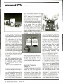
Standard play (SP) at baseband is always
your best signal, as demonstrated by this
oscilloscope trace photograph.
Long play (LP) is next in picture quality.
It has just a bit more staircase overshoot.
Super long play (SLP) increases staircase
overshoot further, but doesn't disturb
colors in this Magnavox VCR.
The multiburst (top) and red field (bottom), r-f in /baseband out, in SP mode
are good for this or any other VCR.
In the LP mode, however, frequencies
from 1.5 MHz and up begin to deteriorate
and noise increases.
At SLP, even the 3.58 -MHz subcarrier
frequency oscillates. The red -field picks
up some noise, as shown.
equipment includes automobile battery
charge cord, recorder carrying case, and
extra batteries that you'll want.
time On and Off, and the particular channel number. Visual monitoring of play/
record functions appear on a lighted
CCD display on the Deck's upper right.
But if you wish to operate manually without special timing, then 30-minute intervals up to four hours may be recorded by
simply pushing the OTR orange button
next to the timer for the desired number
of half-hour segments. Underneath, the
Tuner display glows with softly-lighted
green alpha/numerics for time, day, and
channel settings, plus any CATV and
AFT engaged.
Considering the Deck (Recorder) by itself, however, is another matter altogether. For here must be taken into account
the camera or tuner function, tape speed,
electronic counter setting (with or without memory marks), audio /video or just
audio, Ch. 3-4 output selection, 75 or
300 -ohm U/V inputs, or cable, where
only a single channel may be recorded according to setting.
Then there's a tape length indicator in
5- minute increments and a 0.00 flashing
symbol for the final 5 minutes before
tape's end. Fortunately, hi -fi or normal
audio are automatically recorded; but for
sound only, V/A must be switched to the
A (audio) position when the VR8486SL01
records either hi -fi or lo-fi, including
composite audio baseband output from a
stereo radio tuner -amplifier.
Camera recording is more involved
since you may want to use audio or video
dubbing, other sound tracks, mixed
sounds, or recording of any other tapes.
All this may be monitored through the
TV receiver or on stereo earphones, with
Operation
In the VR8486SL01 combined package,
U/V /CATC recording pretty well follows the routine of any other VCR except
that CATV channels must be chosen and
compensated carefully. First check between channels 5 and 6, selecting whatever CATV NOR /HRC/IRC mode that
produces the best picture. Then see if
other cable channels are compatible also,
leaving the Mode Selector in one position
thereafter for all this particular system's
CATV reception.
Clock and programmed time settings
are routine for program number, day,
September 1985
/
MODERN ELECTRONICS
/
13
PRODUCT EVALUATIONS...
Magnavox Portable VCR continued
There's no more than 1 -dB difference between color bars and redfield at baseband
at SP mode.
Stereo separation between the left and
right channels is an impressive 48 dB.
In its hi-fi mode, the Magnavox portable
VCR displays excellent audio response all
the way out to 20 kHz.
microphone inputs taking priority over
audio or camera /sound inputs.
In all, this is a neat VHS system that
gives you great flexibility in a package
that has reasonable weight for carrying
around and small size when used for
tabletop purposes. It also uses a full -size,
speed slow- motion control, as well as
"still" picture.
The system is a top choice for portable/
home VCR use, but at its rather high
price, the new 8 -mm camcorders could
challenge it in time if enough movie rental
programs become available for the latter
User Comments
This is an impressive little VCR package
for video recordists who do a lot of recording on- the -run and also want all the
features that a tabletop offers, such as
timer programmability. More importantly, of course, is the desire to record and
play back top -quality audio sound, which
this Magnavox makes possible through
its VHSHi -Fi system.
Its video signal -to -noise ratios appear
closer to 39 dB than the 41-43 dB specified
by its manufacturer. But it would be unlikely for a typical user to discern the difference. However, he or she will immediately be aware of the differences in
sound quality when listening to audio
that was recorded from a hi -fi source
the sound is superb! Recording a musical
selection from a good FM stereo station,
using a Luxman tuner, the video tape
copy was indistinguishable from the tuner's direct playback. A top -notch stereo
amplifier /speaker system was used for
playback, of course.
Video quality suffers in the slowest
speed, naturally, where higher- frequency
video is impaired. But this fault, common
with all VCRs, still enables one to record
and view pictures with fair quality.
The LCD readout display isn't anywhere near as good as the more traditional lighted- segment ones, nor do the key
controls have activity indicator lights.
But this is a tradeoff for the mobility that
battery power can give you.
long- recording -capability video cassette.
Furthermore, the wireless remote control
has a full complement of function keys,
including numeric keys and TV channel
up /down keys. It even features variable-
-
14
/
MODERN ELECTRONICS
/
September 1985
format . -Stan Prentiss.
CIRCLE NO. 177 ON FREE INFORMATION CARD
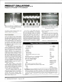
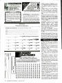
Magnavox Model VR8486SL01 Portable VCR
TV /tuner sensitivity
vhf channels 3/10
uhf channels 15/40
Ac power drain
record
playback
Tape times
play (on time)
stop (off time)
fast -forward & rewind execution time
record
Horizontal resolution (r-f in, baseband out) max.
Audio response, L and R, VHS AFM
Stereo, R/L channel separation
Wow /flutter (NAB at 2 KHz)
SP (Avg /Peak)
LP
SLP
-1/-2 dBmV
+1/-OdBmV
24.96 Wrms
24.48 Wrms
sec
sec
2 sec
3 sec
5
3
3
MHz (SP)
»20 kHz
48 dB
0.00501o/0.0125%
0.0045 olo /0.125%
0.0035% /0.1107o
<4 minutes
Fast -forward /rewind times (120 -min. tapes)
8 hours
Max. record /playback times (160 -min. tapes) in SLP
Heads:
4 rotary
video
3 (2 rotary, 1 sta.)
audio
Test equipment: Tektronix Models 7L5 and 7L12 spectrum analyzers; Hameg Model HM605
oscilloscope; B &K- Precision Models 1260 NTSC color /multiburst, 3020 sweep- function,
2007 stereo generators, and 1035 wow and flutter meter; Sadelco Model FS -3D VU field
strength meter; Data Precision Model 945 multimeter; Sencore Model VA48 video analyst
(modified); Kodak T-120 HGX VC tape; and RCA Model VGM2023S TV receiver
monitor.
Computers
RS -232 Switches
If you've ever hooked up a serial- interfaced device to a computer, especially a
printer, you know what a hassle it can be.
This isn't surprising when you realize that
the venerable RS -232C standard for serial
interfacing wasn't set up for printers and
many other peripherals with connection
to a computer's input /output ports in
mind. Consequently, you can never be
sure which connector pins the manufacturer selected to do what signal or control
chore. To make the interconnected
equipment work properly, you often have
to buy special, costly cables /connectors
or try to modify connections yourself.
The latter course is often taken for reasons of time. This led to development of a
number of devices to simplify this work.
First carne the simple breakout box with
25 interconnecting leads (to match a connector's common DB -25 pins) that could
be disconnected and cross -connected by
moving jumper wires to different terminal sockets. LEDs between data terminal
equipment and data transmission equipment indicates signal activity on a respective line. Once proper pin connections are
known, you can fabricate a custom cable
or modify a DB -25's connections.
More convenient devices are permanently connected fixtures that eliminate
the need to modify cable connections.
Two varieties are examined here: user configurable 8 -pole A -B switches and a
"smart" RS -232 switch that makes proper connections automatically.
Configurable RS-232 Switches
The pair of configurable switches we discuss both feature 8 poles and A-B switching. This combines the capability to custom- configure serial input and output
wiring with the convenience of accommodating more than one peripheral (say,
both dot -matrix and a formed -character
letter -quality printers).
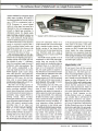
The HackerSwitch 2 from Litek
(Grants Pass, OR 97526) is a $59.95 assembled switch that is really for the computer hacker. It consists of three DB -25
female connectors, an 8 -pole doublethrow in -out push switch, and a series of
wire-wrap terminal strips, all soldered to
a double -sided 71/2 " x 3 " printed- circuit
HackerSwitch -2 uses open construction and terminal posts.
HackerSwitch mounted on a printer.
board. Four posts and screws support a
clear plastic cover and four rubber feet.
Two thick, double-sided adhesive backed foam strips are provided for
mounting the HackerSwitch 2 on the side
of your printer or computer, or on a wall,
with the connectors facing down and the
switch pointing up.
All connector pins (except #1) are
brought to the wire -wrap terminals by circuit traces. The eight wires most commonly used with RS -232C interfacing
(#2 -#8 and #20) are routed through the
switch. All #1 pins (equipment ground)
are wired together and to PC board holes.
Although in is always signal ground, it is
one of the switched lines.
Custom configuration is provided by
simply cutting the traces as required and
using wire jumpers between terminal
pins. These wire jumpers can be soldered
or wire- wrapped.
For example, to swap wires #2 and #3,
usually required for serial interfacing a
printer with a terminal or computer, you
cut the common (center connector) #2
and #3 traces, and use wire jumpers between their terminals. If you ever want to
switch back, just change the jumpers.
If you only want to change an output
connector, you can do that. The whole
idea is that any of the three connectors
can be configured any way you like, with
up to eight lines switched.
The postion of the pushbutton switch
determines which outside connector is
wired to the center connector. Unfortunately, this is not clearly represented on the
unit itself. For one thing, when the switch
is mounted switch -up /cables -down (the
only logical way to mount the HackerSwitch), all printed -circuit board legends
are upside down.
The words IN and OUT, printed in large
letters on the pc board, could refer to the
connectors
natural terminology for
signals. Not so. Instead they refer to the
switch position. Pushing the switch IN
connects the center connector to the connector nearest the word IN on the pc
board. Similarly, when the switch is in the
OUT position, the connector nearest the
word OUT on the PC board is connected
to the center connector. To add to the
confusion, it is not readily apparent to the
eye when the switch is IN or OUT, since
only about a quarter-inch movement is
involved, and there is no close reference
September 1985
-a
/
MODERN ELECTRONICS
/
15
Common
A
8
X
1
2
3
4
5
6
7
2
3
4
5
6
B
7
8
20
7B
88
7C
8C
7A
-0
58 <
5C
<
5A E
l
I
4
5
6
8
20
0000000000
20
X
0/00000.100
0000000/00
X
1
2
3
7
Tigertronics Model S-8.
0--> 8A
LED's. Twenty -seven yellow wires (nine
for each of the three DB -25 connectors)
are soldered to the pc board and inserted
into the connectors. But there are no
wire- terminal blocks!
"Hmmmm ", you say, "I thought this
was configurable ?" It is but without cutting traces or soldering. The connector
wires can be removed and replaced with a
special tool supplied with the Model S -8
6B
6C
I
0->
0
6A
48
3c
I
I
3A
<
0
0-ÿ
XB
28
xc
XA
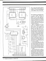
Fig.
1.
2C
0--*
= SIGNAL
2A
DIODES
Internal circuitry of Tigertronics' Model S -8 RS-232 switch.
surface. Nonetheless, these are minor
complaints. The device does its job well at
a reasonable cost. Should you need to
configure and switch more than two outputs, there's a HackerSwitch 3 at $79.95
that switches one device between three
other devices.
When I first saw the HackerSwitch 2 I
was impressed with its simplicity and cleverness. A good idea, easily accepted by a
typical hardware- oriented computerist
with no fear of soldering or wire -wrapping. Then I discovered the Tigertronics
Model S -8 -the same idea, but implemented for the no- dirty -hands crowd.
The Model S -8 RS232 Switch (Tiger tronics, Inc., 2734 -C Johnson Drive,
Ventura, CA 93006) is available assembled for $79.95 or in kit form (Model
S -8K) for $59.95. (Add $3 S and H; and
6% Sales Tax for California residents.)
This design is completely enclosed in a
16
4A
solid, two -part 5 " x 5'/4 " x 2'/4 " tan
plastic cabinet with four rubber feet.
Two red LED's on the front panel,
marked A and B, tell the user which
switch position is active. These are driven
from some clever internal circuitry (Fig.
1) that lights the switched LED using the
lower voltage of either pin #2 or #3. Additionally, the in -out push switch has a large
black cap, and its position in relation to
the front panel is clearly shown with symbols for the A and B positions.
The back panel clearly marks the three
DB -25 female connectors as COM., A,
and B. There is absolutely no confusion.
Remove two screws from the bottom of
the cabinet of the assembled unit and the
top -half slips right off to reveal a square
double-sided pc board held down with
four screws. The switch is identical to the
switch used on the HackerSwitch 2. Two
diodes and a resistor are used with the two
/ MODERN ELECTRONICS / September 1985
(or Model S -8K).
Each wire has a special pin on its end.
This pin, when inserted into any connector socket from the back, locks into position, but can be removed with the extractor tool. You place the extractor tool
around the wire you wish to remove and
press into the face of that pin with a paper
clip while you pull on the extractor from
the back. It takes very little practice to
remove a pin from any connector position and insert it into another. Swapping
pins #2 and #3, a common requirement,
takes less than a minute.
Pins #1 are connected together, and not
switched. Pins It/7, signal ground, are all
connected to the ground foil of the pc
board, and are not switched. Pins #2, 3, 4,
5, 6, 8, and 20, and the LED's, are
switched. This unit is more sophisticated
than the HackerSwitch model, but it is
$20 more costly.
You can save $20, however, by assembling the kit version. This essentially involves soldering the 24-pin switch, 2
LED's, two diodes, one resistor, and 27
wires to the pc board. You then use screws
to mount the three connectors to the rear
panel, insert the LED's into small holders
on the front panel, screw down the pc
board to the cabinet bottom, insert the
(Continued on page 93)
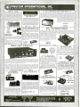
PINECOM INTERNATIONA
,
INC.
12603 CRENSHAW BOULEVARDHAWTHORNE, CALIFORNIA 90250. 213) 679-9999
-
0 -15
MARK IV
15 STEP
LED POWER LEVEL INDICATOR KIT
Thrs new stereo indicator kit consists of 36 4-color
LED's (15 per channel) to indicate the sound level output of your amplifier from 36dB to + 3dB. Comes with
a well designed silk screen printed plastic panel and
has a selector switch to allow floating or gradual out pur indicating. Power supply is 6-12VDC with THG on
board input sensitivity controls. This unit can work with
any amplifier from 1W to 200W. Kit includes 70 pcs
driver transistors, 38 pcs matched 4 -color LED's, all
electronic components, PC board and front panel.
This is
-
MARK IV KIT
$31.50
20 STEPS BAR /IDOT AUDIO
LEVEL DISPLAY KIT
This new designed audio level display unit is using a
new integrated circuit from National Semiconductor to
drive 20 pieces of color LED's (green, yellow and red)
on each channel. It provides two types of display
methods for selection 'bar' or 'dot'. The display range
is from - 57dB to OdB. Kit is good for any amplifier from
2 watts to 200 watts) Power supply requires 12VAC or
DC. So it is great for cam as well! Kit comes with printed
circuit board, all LED's, electronic components, switches, and silk screen printed professional front panel.
MODEL TY -45
TA -1000
KIT
$51.95
Power
Transformer
$24.00 ea.
100W CLASS A
POWER AMP KIT
Dynamic Bias Class "A" circuit design makes this
and unique in its class. Crystal clear, 100 watts power
output will satisfy the most picky fans. A perfect
combination with the TA-1020 low TIM stereo pre -
arrp.
Specifications Output power 100W RMS into 811.
Frequency response
125W HMS into Oft
THD less than 0.01% S/N ratio
10Hz- 100KHz
better than 80dB Input sensitivity V max. Power
supply o40V at 5A.
VOLT 2AMP REGULATED POWER SUPPLY KIT
processional power supply kit. Output voltage adjustable from 0- 15VDC. Output current
also can be limited to two range sections such as 200mA and 2A. An elaborated protection system
also designed to give out a beeping sound and a flashing LED warning will appear when output
was over loaded or short circuited. High stability and reliability resulting from employing a high
quality voltage regulator IC. The front panel of the power supply is well designed with output terminals, on /oft switch, voltage adjusting control, jumbo size meter for reading both AMPs and VOLTs,
Also with a volt/amp switch as well as current limit
select switch. Kit comes with refined metal case.
silver color with sand brushed front panel, all electronic parts, pc board, 3" jumbo size meter,
transformer, circuit diagram and instructions.
a
TR -100 KIT
$59.50
$38.50
TONE CONTROLS
Only $44.50
Transformer
TA -800 KIT
$4.50 ea.
$65.00
Transformer (52VCT 4A)
DISCO LIGHT ORGAN KIT
$22.50
60W
* SPECIAL *
a
Excellent Price!
Model 001 -0034
$29.50 per Kit
Transformer
fODN11 MASTER
.
w2w.
$10.50 ea.
LIGHT COMTIIOLLIR
TA -322 30 WATTS TOTAL
15W + 15W STEREO AMP KIT
TY-ITS
The TY-23B Color Light Organ is designed for use at home, party, disco or commercial advertisement purpose. It gives you the moving light effect coordinated with the frequency of the music
changes. When music or an audio signal input is fed into this unit, it will be divided into High, Medium
and Low frequency by means of an electronic equalizer circuit to drive three groups of light bulbs.
Each group of lights has an independent sensitivity control.
This is a solid stale all transistor circuitry with on
board stereo pre -amp for most microphone or phone
input. Power output employs a heavy duty Power
Hybrid IC. Four built on board controls for,
volume, balance, treble and bass. Power supply
requires 48VCT 2.5A transformer. THD of less than
0.1% between 100Hz -10KHz at full power (15 Watts
15 Watts loaded into 814
Besides working as a Color Light Organ, the TY-23B also can be used in "Light Chaser" mode
toperform light effects for signs as follows: (1) Switch on one after the other. (2) Flashes all together.
(3) Switch off one after the other. Flashing rate can be controlled. The output power of this unit
is3,000 watts (110V) which is 30 100 watt color spot lights or 600 5 watt light bulbs. Build one
of these color organs today and enjoy watching your music. Great for school projects! Ali electronic parts, metal case, predrilled pc board and instructions come with kit.
MAGNETIC HEAD EQUALIZER
Standard RIM curve for all kinds of magnetic heads 3
stages crossover circuit for best results Output voltage
guaranteed to be stable without any oscillation Power
Supply: 24 V.D.C.
$64.50
TY -23B DISCO LIGHT ORGAN KIT
TY -41 INFRA -RED
REMOTE SWITCH KIT
KIT
POWER AMP
TA -800 is an 80 watts + 80 watts stereo. The Low T.I.M. preamplifier employs a low distortion linear
I.C. (LM4558) and three negative type tone controls for High, Medium and Low frequency control.
The rear power amplifier uses newly developed high frequency darlington hybrid type transistors
(AN7337/AN7338) in a push -pull circuit. There is also on board speaker protector to generate
a delay time between the speakers and the
amplifier. Large aluminum heat sink, which is
mounted on pc board, requires no external hookup wires. The kit comes with instructions, all
electronic parts, predrilled pc board, and heat
sinks. Power transformer not included. Easy to
build, guaranteed to work.
(
1
-80W STEREO AMPLIFIER
-
80W +
PRE -AMP
LOW TIM DC STEREO PRE -AMP KIT TA-2800
Incorporates brand-new DC design that gives a frequency response from 0- 100KHz ±0.5dB. Added
features like tone defeat and loudness control let you
tailor your own frequency supplies to eliminate power
fluctuations!
Specifications:
THD/TIM less than .005% Frequency response DC to 100KHz '0.5d13
RIM
deviation = 0.2dB
S/N ratio better than 70dB
Sensitivity; Phone 2mV 47K11, Aux 100mV 10OKf1
Output level 1.3V Max output 15V Tone controls:
Bass r 10dB
50Hz, Treble -t 10dB 4/ 15Hz
Power supply r24VDC Or 0.5A. Kit comes with
regulated power supply. All you need is a 48VCT
transformer no 0.5A.
-
60W O.T.L. AMP
Ste,eu pre -amp r lone control power amp. All in on
unit, fully assembled! Compact in size: 7"x43A "x2'e ".
Can be fitted into most cabinets. Power transistors
using 25C1667 X 4 to give a max output of 60W +60W
(811)
Total
Frequency response: 20Hz- 85KHz( - 1dB)
harmonic distortion: 0.02% (1 KHz) Signal/Noise Ratio:
Tone control: 100 Hzs16 dB 10
KHz! 14d13 Dynamic range: 60 dB Power Supply:
48V - 70V 5Amp. FitterCapacitor: 4700075V or better.
88 dB (open loop)
MODEL:
SA-4520
Part #370 -0350
1
2
$39.95 ea.
Transformer Part #670- 0230... $22.50 ea.
Filter Capacitor 4700µF 70V
$6.50 ea.
STEREO MIC. AND ECHO MIXER
FOR STEREO AMPLIFIER SYSTEM
The circuitry employs all integrated circuits, BBD type
echo circuit. echo time can be adjusted (max. .30
Msec.) Also with a microphone preamp on the board.
Fully assembled.
DIGITAL PANEL METER KIT
MODEL: MA -142
Part #370 -370
$6.95 ea.
0 -30VDC
MODEL: MX205
Part #370 -0360
$29.95 ea.
POWER SUPPLY KIT
4
LOW T.I.M.
TRANSISTORS
Digit Multi-Use Dane! Meter. The TY -43 digital
panel meter kit using the IC 7107 A/D converter from
Intersil is a principal component which direct drives a
16mm high 31/2 digit LED display. The unit needs very
few external components and is extremely easy to
assemble and adjust. You can produce various kinds
of voltage, current and resistance measuring meters,
by adding a limited number of components, you can
even change it into a thermometer, frequency counter
and capacitor meter. (Application Circuit diagrams
enclosed with kit).
3Y2
This infra-red remote control switch kit is suitable for
many kinds of electrical and electronic applications,
such as light controller, garage door opener, TV on /off,
alarm system and many others. It does not use any
antenna to transmit the signal, but it transmits an invisable light signal so the receiver can pick it up as far
as, 30 ft. away. Kit comes with all electronic components, pc board. relay and the infra-red LED.
TY -41 INFRA -RED SWITCH KIT
$23.50
SEND ONE DOLLAR
FOR OUR DETAIL CATALOG
Inside California
Outside Calif. (incl. Mexico 8 Canada)
Overseas
Input sensitivity is DC ± 199.9MV full scale
Input impedance is lore ohms
Operating source is 5 - 6VDC S 150MA
Overall size: 11/2" x 4"
TY -43 DIGITAL PANEL METER KIT
Shipping 8 Handling Charges
Under $50.00 OverS50.00
Purchase
Purchase
10%
15%
25%
a
5%
10%
20%
100W
This kit includes a high etticency regulating circuitry. By
using the IC 723 and darlington power transistor to provide a stable and ripple free DC voltage from 0 - 30 volts
at 3 amps or 0 - 15 volts at 5 amps (depends on the
power transformer used, not included with kit). Overload
and short circuit protection also featured on this kit. Easy
to build! Guaranteed to work! All electronic parts, pc
board, heat sink for power transistor. Instructions included.
TR -355 POWER SUPPLY KIT
$31.50
$14.50
24VCT Transformer (for 0 -30V)
$10.50
Minimum Order $10.00 /Calif. Residents
add 6.5% Sales Tax. Phone Orders Accepted
on VISA or MC ONLY. NO C.O.D.'s. Prices subject to change without notice.
CIRCLE NO.
175 ON
FREE INFORMATION CARD
100W
Employs Hitachi low noise I.C. for pm-amp Max.
output 16 V P -P (non distortion) With hi -low filter, and
tone defeat circuit Rear power amp with short circuit
protection Giant heat sink for maximum results Tone
controls-, 4dB All components (except pots for volume, and tone controls) are pre -assembled, the quality
is guaranteed. Power supply DC . 35V-50V
1
MODEL: SA802C
Part #370-0340
$85.00
POWER TRANSFORMER
(68V -80V CT 6 AMP)
Part #670 -0220
$24.50
STORE HOURS
MON- FRI -10 -7
SAT-10-6
mr a
rat!lwje
i
Ì.
..
What can you do
Just about
CIE
can show you how.
Computer technology. Satellite communications.
Cable television. Cellular radio. Cigital electronics.
Robotics. Just a few of the hottest caree.' areas
in electron'cs. The ones everybody is talking
about. The ones that are chancing the way we
live, the way we do business, the way we entertain ourselves. The best way to start a career in
any of them? By learning the basic electronics
theory and principles of how they work from CIE.
Join a leader.
Leading the world in specialized eectrorics trairing, CIE is the largest school c1 its kind with over
25,000 students at home and abroad. And with
over 50 years of experience teaching electronics
to thousands of men and women through proven
methods of independent study
room sessions.
without class-
Learn as much as you want,
when you want.
Whether you're interested in learning new sk=lls
or upgrading old ones, earning a diploma or an
A.A.S. degree, CIE can match your needs with
courses and programs that let you start where
you want, go as far as you want from a basic
beginner course all the way to CIE's Ass =ociate
in Applied Science Degree in Electronics -a
comprehensive program that prepares yogi fcr
advanced electronics careers.
Custom training
equipment helps you learn.
CIE believes in the importance of learning by
with electronics?
z nyth i ng.
doing. So most of our courses include specialized training laboratories keyed to specific lessons for practical experience through teaching
experiments. Our CIE Microprocessor, for
example, comes fully assembled and ready to
use to teach you how a computer CPU works
through a series of experiments you perform
on your own.
E
1776 East 17th Street
Cleveland. Ohio 44114
Pleise send me your CIE Of -Campus Studies Catalog.
I
I
Are you ready?
you're ready to do something now about your
future, there's no waiting to enroll with CIE. Get
all the information you need to enroll simply by
calling us toll -free at 1- 800 -321 -2155 (in Ohio,
1- 800 -362 -2105). Or mail in the handy reply
coupon or card to Cleveland Institute of
Electronics, 1776 East 17th Street, Cleveland,
Ohio 44114.
World Headquarters
Cleveland Institute of Electronics, Inc.
including detai s about the Associate Degree program.
understand there is no cost for the catalog and a CIE
representative may call, but tnere is no obligation.
Print Name
If
Address
Apt. No
City
Age
State
Zip
Area Code /Phone No.
Check box for G.I. Bill bulledn on Educational Benefits
I
Veteran
Active Duty
MAIL TODAY!
MO.40
RCA's latest "Dimensia "A /Vsystem now has a 4041-screen projection TV /Monitor with microprocessor intelligence.
Audio and Video
In Your Future
... As foretold at the 1985 Summer Consumer
Electronics Show
By Len Feldman
usual, the recently concluded Summer Consumer
Electronics show, held on the
shores of Lake Michigan in Chicago,
was the "biggest" and had the "highest attendance ever." Of greater interest to most of us, though, is not so
much the health of the electronics inAs
22
/
MODERN ELECTRONICS
/
dustry as the wealth of new products
shown by more than 1300 exhibitors.
These are the models you'll soon be
seeing in stores. The star categories
of the show were, without a doubt,
audio and video. Futhermore, integration of audio and video products
seemed more complete than ever before, as one company after another
continued to echo that frequently
overused phrase -"The marriage of
audio and video."
September 1985
There's always a large room at the
show dedicated to the most innovative and original new products. A
panel of judges, including myself,
was given nearly 500 entries from
which to choose the products for this
special exhibit within an exhibit. We
ended up selecting more than 150 of
them, which were displayed in this
tasetefully furnished room designated as the Design and Engineering
Award display. More than 70 of the
ASV
September 1985
Technics' SL -XP7 portable CD player is now "Smallest
CD Player" and adds 15-selection programmability.
Sansui's one -brand, remote -control system has twin threeway tower speakers.
items seen in that room were audio
related, while nearly 50 more had to
do with home video. From this vast
array of new and exciting audio and
video products I've chosen just a few
that particularly attracted my attention. Not all of the exciting products
ended up in this special exhibit. Some
had to be ferreted out by touring such
out -of- the -way places as private hospitality suites in far -flung hotels.
Others were to be founded in smaller
exhibits relegated to hotels which
were part of the show, but were geographically removed from it.
Audio /Video Systems
The all -in -one audio /video system is
here, and in the months ahead you
will see more and more of them. Furthermore, A/V systems have a great
deal going for them. Call it synergy
or whatever you like, but when one
manufacturer has total control over
all of the elements of a home entertainment system, that maker can provide the user with convenience features that are generally appealing.
For example, being able to work with
a single, hand -held wireless remote
control and have all of your video
and audio components respond to
commands initiated from that single
device could not be easily accomplished with separate components
assembled by you.
The first, and perhaps most comprehensive audio /video system, was
introduced by RCA last September.
RCA calls its Dimensia system "Intelligent" Audio Video. The key to
the system is the color monitor /receiver, with its multi- function built in microprocessors and the single
wireless remote control that commands all seven components within
the system. With this single instrument, you can control all VCR programming, playing and recording
functions. All controls of all the
other components are also accessed
by means of this single remote unit.
All audio components operate independent of the video components; all
volume levels, all stations selections,
all channels are easily selected by the
single "control center."
The user can even perform multiple functions simultaneously. For instance, you could record a broadcast
TV channel on the VCR while recording an album on the stereo cassette
deck, and at the same time watch a
completely different TV broadcast
channel. While the system can be sold
in its entirety, it can also be assembled by the user a few components at
a time. The 26 " monitor /receiver
must be the first component, of
course, since it is the one that comes
with the ingenious wireless remote
control center. Other component options that make up the system include
a VHS HiFi VCR, an integrated amplifier, an AM /FM tuner, an audio
cassette deck, a linear-tracking turntable, a CD player, and a pair of
loudspeakers.
One of the most innovative high tech features of the Dimensia system
is the 26" monitor's display, which
keeps the user informed of every
component's status. This display will
even provide simple, easy-to- understand instruction for performing the
various component functions. Interconnection of the various components is extremely simple, employing
a sort of daisy -chain arrangement
that RCA calls SystemLink.
Flexibility of the RCA "Dimensia"
system extends beyond its remote
control and interactive functions.
The components can be arranged in
either double or triple cabir. 2.t setups.
September 1985
/
MODERN ELECTRONICS
/
23
"Audio /video and one -brand audio take center stage."
A second -generation version of Dimensia at the Show gives you the option of a 40" (measured diagonally)
rear -projection TV monitor /receiver
instead of the 26" direct -view TV set
offered with the original "Dimensia"
system. The second Dimensia system
also offers an optional ten -band
graphic equalizer and a more powerful integrated amplifier (100 watts
per channel instead of 50).
Just about every other major exhibitor at the show had one or more
complete audio /video systems on
hand. Some of the more noteworthy
came from such well known audio
companies as Pioneer and Technics,
with video -oriented companies such
as Sanyo and Panasonic offering a
variety of A/V system as well.
While not offering one -brand systems in the conventional sense, Kyocera showed three new components
(a 100 -watt receiver, a cassette deck
and a CD player), each of which can
be remotely controlled using the
same remote hand -held unit by connecting the components themselves
to a remote sensing unit. This arrangement even permits multi-room
remote control. Other companies
showing single audio components
that can be remotely controlled included Luxman, Parasound, Yamaha, and Sansui, while NEC displayed
a new A/V amplifier /control center
with a wireless remote.
If audio /video and one-brand audio system took center stage at CES,
that's not to say that many outstanding individual components weren't
just as newsworthy and spectacular.
Perhaps the most outstanding individual audio component introduced
at the show was Technics' remarkable new portable CD player. Clearly
snatching the "World's Smallest CD
Player" title away from Sony Corporation, the tiny Model SL -XP7 obviously represents a case of "one ups manship" against the earlier- introduced Sony D -5. The Technics CD
player is not only smaller than the
24
/ MODERN ELECTRONICS / September
P' Ry
L
..
..
-;
The dbx DX3 CD player uses unique enhancement circuits to improve sound.
Sony unit (20% smaller outside its
battery case, 40% smaller when
housed in the battery charger/case
compared to the Sony unit similarly
configured), but it offers 15- selection
random programmability plus display features not found on the Sony
D -5. Its resistance to shock is also
said to be superior to that of the Sony
unit. The Technics player measures
just under 5 " wide by 1'/a " high by
under 5 " deep.
The most unusual table -top CD
player introduced at the SCES was
one from dbx. The dbx Model DX3 is
aptly named, since it offers three
special features not found on other
CD players. The first of these is a
special compression circuit. Many
listeners of CDs have noted that there
are situations in which the dynamic
range of some CDs is too great to be
enjoyed. For example, in an atmosphere where ambient noise levels
are relatively high (e.g., inside your
car or in a noisy residential setting), if
you turn up the volume on your system so that you can hear the very
quietest passages on some CDs, the
loud passage that comes along will
either blast you out of your seat or
else they will overload your system's
amplifier. Having a built -in, switch able compressor means that you can
listen to Compact Discs at background music levels without loss of
quiet passages. Also, you can make
compressed cassettes for car stereo
systems and personal portable using
the Compressor feature.
1985
A second feature of the dbx CD
player is "DAIR," which stands for
Digital Audio Impact Recovery, a
circuit for adding impact to the transient attacks of music. This circuit
was especially redesigned for the
digital era.
Ambience control is the third "extra" found in the dbx DX3. Many
audiophiles have maintained that
some CDs sound better with an increase in out -of- phase, L-R information. The Ambience circuit allows
users to either increase this component, essentially enlarging the stereo
image, or to decrease it when tighter
musical imaging is desired.
Another entry from dbx was a
lower -priced version of its Sound field One speaker system. The
Soundfield Ten, like its predecessor,
allows a listener to sit almost anywhere in the listening room without
losing balanced, accurate stereo reproduction. The system expected to
sell for about half the price of the
earlier Soundfield One, comes with
an outboard controller that has high
and low frequency compensation
controls, an ambience circuit for
added spaciousness and a "wall EQ"
switch that compensates for the effect that against-the -wall placement
has on loudspeakers.
Digital Audio Via Video
It is no secret that a large committee
of engineers and scientists has been at
work for several years trying to agree
"... 24 continuous hours of digital audio on a single 8-mm cassette."
upon a standard for consumer digital
audio tape recording. Of course, it
has been possible for several years to
use a VCR in conjunction with a
PCM Processor to record digital
audio on video tape, but many have
objected to this two -component approach to digital tape recording. A
dedicated system for digital audio
tape recording, popularly known as
DAT, has been long in coming. In
fact, such standards, though almost
ready for public disclosure, have still
not been announced. It was therefore
much to everyone's surprise that a
totally unrelated digital audio tape
recording system was shown at the
CES by Kodak and, in a suite removed from the show, by Sony.
The surprising aspect of this disclosure was the fact that the recorders
used for the new digital audio tape recording system were VCRs after all.
But instead of using 'h " videotape,
these tiny machines used the new 8
millimeter video tape package. The
8 -mm system standardized a few
years ago made provision for stereo
PCM (digital) audio tracks along
with video pictures, and indeed the
machines demonstrated by Sony and
Kodak at CES were, for the first
time, able to record digital stereo
sound tracks along with a much improved 8 -mm video picture.
But that's not the big surprise. In
addition to the new video- plus -PCMaudio recording capability, Sony's
newest home 8 -mm deck is also able
to record six pairs of stereo tracks, sequentially, using a digital PCM recording format. Since two -hour
8 -mm tape cassettes are now a reality
(only 90- minute tapes had been available), that means a potential audio
recording time of six times two
hours, or twelve hours all together!
And as if that weren't enough,
Sony's unit offers a slower speed
(aptly dubbed LP) that increases recording time to four hours per tape.
So, if you use that tape for audioonly PCM (digital recording) you can
Kodak's MVS -5380 8-mm VCR features digital stereo sound recording.
record 24 continuous hours on a
single cassette that's not much larger
than a standard audio cassette. The
Kodak version of the home 8 -mm
VCR has only the one speed and you
must therefore settle for a total of
"only" 12 hours of audio-only PCM
recording.
The PCM format agreed to by 18
companies for this 8 -mm tape application does not provide as high quality audio as is available either on
Compact Discs or on the DAT formats yet to be proposed. Nevertheless, the audio quality is superior to
that obtained on conventional tracks
of either Beta or VHS half-inch video
tapes. Specifically, frequency response extends to 15,000 Hz (as good
as FM radio and the stereo sound of
multi -channel TV), while dynamic
range is better than 80 dB.
The sampling rate is 32.5 kHz, and
the equivalent of a ten -bit digital
code is used. Normally, a ten -bit
sampling code might be expected to
yield a signal -to -noise ratio no greater than about 60 dB. The additional
20 dB of dynamic range is achieved
using a system of linear companding
(compression during recording, inverse expansion during playback).
Early reactions to this system were
favorable, in that there was no apparent "breathing and pumping" audible with the chosen linear companding system. The question in everyone's mind now is this: will PCM
audio recording on 8 -mm tape become a competing system to the yet-
to -be announced DAT format? And
even more to the point, if the DAT
standards committee ends up proposing two DAT formats (one using
rotary heads, the other stationary
heads) as is now suspected, does that
mean that consumers will be faced
with having to choose from among
three totally incompatible home digital audio tape systems?
High-Fidelity AM
If you haven't been all that excited
about AM stereo up to now, no one
can blame you. The AM tuner sections of most high -fidelity audio tuners and receivers are, for the most
part, treated as an afterthought. Response is often deliberately cut off
above 2 or 3 kHz, and dynamic range
is severely limited. Yet, AM radio has
always had the potential for much
better sound reproduction. Many of
you may remember an excellent AMonly tuner manufactured and distributed in North America as the
McKay -Dymek tuner; its response
was virtually flat to well beyond 10
kHz and its sensitivity was superb.
Bob Carver, the innovative president
of Carver Corporation, feels that the
McKay-Dymek was just a bit ahead
of its time, and that if it were available now, with stereo decoding built
in, it might well prove to be a winning
product. Accordingly, Carver proposes to add a superlative AM tuner
section to his well-accepted TX -11
FM Tuner. He demonstrated a pro-
September 1985
/
MODERN ELECTRONICS
/
25
"AM radio response to 15 kHz claimed."
Carver Corp. 's new 2000 receiver produces an incredible 200 watts /channel
from its built -in "magnetic field" power amplifier.
totype of that AM circuit during the
CES and, indeed, sound quality was
almost indistinguishable from FM.
Claimed response extended to 15
kHz, an achievement made possible
with the aid of a very sharp 10 -kHz
"whistle" filter that eliminates adjacent-channel interference beats, but
is so narrow in its band -elimination
range that you hardly notice it's
there. Even more astonishing, addition of this AM circuitry to his tuner
would only add approximately $25 to
$35 to its total retail price.
Just in case Carver's AM tuner addition doesn't take off, the energy laden Carver developed a second
generation all -in -one receiver
Model 2000- which delivers an incredible 200 watts per channel, includes a remote control, and has Carver's other special circuits such as his
"Sonic Holography" and special FM
circuits that help reduce noisy reception from weak signals. The high
power level of this receiver stems
from Carver's so-called magnetic
field amplifier technology and it
comes just when everyone is clamoring for more power with which to
handle the wide dynamic range of
-
26
/
MODERN ELECTRONICS
/
new digital program sources such as
CDs and PCM tape recordings.
Stereo TV Decoder Add-On
By year's end TV viewers in most regions in the United States will be able
to receive at least one TV station that
is broadcasting some or all of its programming in stereo or in a second
language using the so- called S.A.P.
(Secondary Audio Program) facility
of the new Multi- channel TV Sound
System. Most TV viewers wishing to
receive broadcasted stereo sound,
however, will be faced with a problem because older TV sets cannot be
easily converted to stereo. Such conversion would require wiring in a special multiplex jack that might not
work with available outboard stereo
TV decoders. Furthermore, wiring in
such a jack and providing external
access to it could expose one to dangerously high voltages. Only a very
few of the TV sets built in recent years
have safe multiplex jacks incorporated, and still fewer sets have built -in
stereo decoders.
So, what's the owner of a perfectly
good color TV set to do if he or she
September 1985
wants to listen to stereo TV or to bilingual broadcasts in that second language? The well known FM circuit
designer, Larry Schotz, who has been
a design consultant for such reknowned companies as Crown International, NAD, Proton and Nakamichi, came up with a clever solution. He noted that most TV sets (and
older ones in particular) radiate a certain amount of high- frequency energy. Some of that radiated energy is at
4.5 MHz, the frequency of the sound
carrier after video detection. Schotz
designed a stereo decoder which, in
addition to conventional connection
to a TV set's multiplex jack, can be
used with a special small "r -f probe"
that is supplied.
The plug at the end of the probe is
connected to the input of the decoder, while the "business end" of the
probe is carefully and slowly moved
around the surfaces of the TV set's
cabinetry. With audio cables connected from the decoder's output
jacks to your stereo system's inputs,
a point will be found where maximum 4.5 -MHz r -f energy is radiated
from the TV set and sound will be
heard coming from your speakers. If
the TV signal is being broadcast in
stereo, a light will illuminate on the
front panel to indicate that fact. Even
in mono, though, sound will be much
improved, since you will be bypassing your TV set's own minimal audio
amplifier and tiny speaker. Mr.
Schotz has licensed his "wireless"
stereo TV decoder to Recoton Corp.
As usual, there were plenty of new
loudspeaker models from a wide variety of manufacturers. Among the
unusual ones was the John Bowers
Ltd. "Active I" loudspeaker
powered speaker system that
achieves large loudspeaker performance from a comparatively small
enclosure. If the John Bowers' name
is unfamiliar to you, he is the Mr.
Bowers who heads up the well known B & W Loudspeaker firm in
England. He felt that this new entry
-a
"A laser -beam pickup for LP records ?"
Video & FM audio & digital stereo
Multi -channel PCM
Tape Run
Tape Run
Band
mm
Video 8 FM
Monaural Audio
/
S
Visions Of Things To Come?
In traversing the seemingly endless
acres of show floors that make up the
Summer CES, I always keep my eye
out for something that is really un-
usual -even improbable. Touring
the smaller exhibits located in the off the- beaten -path hotels and manned
by young companies just getting
started, there was no shortage of really "far -out" products. To "sum up
PCM Sound Tracks
m Video Region
in Standard Location
At left is illustrated the helical track configuration for
8-mm video, which reserves one -sixth of the track for digital stereo sound information. For multichannel audio
company name.
Not to be outdone by its chief United Kingdom competitor, the KEF
Electronics Ltd. Company, introduced a series of six loudspeakers
called the C-Series. The least expensive of these, the C -10, suitable for
shelf or wall mounting, carries a price
tag of $220 per pair, while the most
expensive C -80 has a suggested retail
price of $1050. KEF's special conjugate circuitry, first used in its Model
104/2, reportedly balances out unevennesses of the drive unit and the
network load by means of "mirror
image" components that cancel out
impedance peaks and dips.
8mm
PCM Sound Track
Digital Stereo Audio
was so different in concept from the
passive systems produced under the
B & W name that he decided to produce it under a separate, subsidiary
yOe
tapes, the video region is replaced by five more audio
tracks that are identical in format to the standard PCM
audio track format, illustrated at right.
this summary," let me describe what
I consider to be the most unusual
and most unlikely product talked
about at the CES.
The company's name was Finial
Technology & Innovation and, as I
might have suspected, they were to be
found not in the main convention
center, where the "big" companies
hold forth, but in a small hotel room
at the nearby Americana- Congress
Hotel, on Michigan Avenue. That
hotel, along with the smaller Blackstone Hotel, was reserved for the
smaller, so-called "esoteric" or high end audio companies who could neither afford nor wanted to be on the
"main exhibit" floor.
There was no sound at Finial's exhibit. Instead, there was nothing
more than a museum -like display of
phonographs- ancient and not so
ancient. Starting with an Edison cylinder- phonograph, as I turned about
the room I saw disc turntables and,
finally, a CD player. Robert Reis, the
intense young President of the firm,
approached me when he saw me gazing at the CD player. "You are looking at soon- to -be- obsolete technology," he said. As I turned to face the
last part of the exhibit, he explained
that it was a mockup (not even a
working prototype) of a new kind of
record player that he and his staff
-
had perfected and that actually was
in working order "back at the lab."
This record player, said Reis, was designed to play conventional LP records using a laser beam instead of a
stylus and cartridge assembly following the wiggles in an analog record.
He must have seen how incredulous I was, because he invited me to
join him in his private hotel room for
further discussion. He and his marketing manager, Michael May, spoke
earnestly for several minutes, and
when they were through I was prepared to believe that perhaps they
could perform this feat after all. As
they pointed out, there are some 30
billion analog records out there in the
world, and if a way could be found to
play them more accurately than they
had ever been played, and with no
further wear, that might be a very
worthwhile thing to do. The gentlemen from Finial maintain that they
have perfected such system and that
they will be exhibiting it at the next
Consumer Electronics Show, or perhaps the one after that.
I'm willing to keep an open mind
about this "optical turntable." Perhaps next year Finial will be on the
show floor with a model that works.
After all, I can remember when talk
of digital audio discs was greeted
with a certain amount of skzpticism!
September 1985
/
MODERN ELECTRONICS
/
27
Home Brewing
Dress Up Your Projects
The simple photographic procedure described here
will let you produce project front panels that are
indistinguishable from those on commercial products
you don't have to be specially trained
to turn out professional -looking
panels, and all materials are readily
available at reasonable cost.
By C. R. Ball
the last time you
really finished a project,
taking the time to give it a
professional-looking front panel,
with control legends and perhaps an
eye- catching logo neatly and permanently rendered? If you're like
many hobbyists, you just spray on a
coat or two of enamel paint and label
your panels with a dry-transfer lettering kit or a plastic tape labeler. Drytransfer lettering is okay at first, but
it inevitable wears away and /or
drops off, while tape labels give a
project an unprofessional "klugy"
look, no matter what other pains you
might take to give is a classy appearance. Worse still, both types of
labeling eventually wear away or
drop off, leaving you with a project
whose control functions are a complete mystery if you haven't used it
for some time. This is obviously
leading up to something.
That something is the fact that you
can make very durable front panels
that are indistinguishable in appearance from those you see on corn mercially -made products. Using the
procedure described here, you can
make panels and decals that really
dress up your projects, actually making you want to display them with
pride. You can even use this procedure to make printed- circuit corn identification overlays
ponent
similar to the silk screening used on
commercial pc boards. Best of all,
When was
28
/
MODERN ELECTRONICS
Types of Nameplates
Fig. I. Starting with positive art, first
exposure and development produces
the negative shown at the left. This
negative is then used as original art to
expose and develop the positive film
shown at the right.
Fig. 2. After penciling your layout
onto paper, cover with transparent
film and use dry- transfer lettering
and other drafting aids to transfer the
drawn image. If the image is very
small or contains lots of fine detail,
work twice life size and then have the
image photographically reduced.
/ September 1985
There are a number of processes for
making professional- looking nameplates, all requiring easy -to -use light sensitive material. Some nameplate
fabrication methods use the lightsensitive material for selectively coloring, etching or screening a panel.
Another process uses the light- sensitive material as the finished nameplate image. These fabrication methods go by such names as anodizing,
etching, silk- screening, and photo reproducing, respectively.
Anodized Nameplates are prepared by trapping various colored
dyes in the "pores" of an aluminum
nameplate panel. The pores are
opened electrolytically by immersing
the aluminum (as the anode) in a sulfuric -acid solution. Then the opened
pores are selectively filled with colored dye through an exposed and developed light- sensitive material (photoresist mask). The pores are then
closed by immersing the panel in a
boiling-water solution, permanently
trapping the dye pattern under the
surface of the aluminum.
The anodizing process produces an
extremely durable and attractive
nameplate. Since you can use any
thickness of aluminum, the nameplate can be self- supporting and,
therefore, be used as part of the chassis or as a front panel.
START HERE IF YOU REQUIRE A NEGATIVE
PANEL, LABEL OR OVERLAY:
START HERE IF YOU REQUIRE A POSITIVE
PANEL, LABEL OR OVERLAY:
Original art (positive)
Original art (positive) or
reversing film negative
E
Expose reversing film
with UV lamp
Expose panel, label or overlay
with UV lamp
i0"-i2"
Clear glass sheet
Clear glass sheet
Original art
(image side down)
"Right reading" original art or
(reversing -film negative)
Reversing film
(emulsion side down)
Work
Photo- sensitized metal or
plastic label
(colored/emulsion side up)
surface
1111P.
Developer
Developer
Exposed reversing film
(emulsion up)
Exposed panel, label or
overlay
(colored /emulsion side up)
Glass sheet
Glass sheet
3
S
Work
surface
et stand about 20 seconds. Then gently rub with cotton or a developer pad to bring out image. Continue to
rub until all unwanted areas of emulsion have been removed. Thoroughly rinse under gently running cold or
tepid water. Pat gently with paper towel to dry.
Film negative (use
as
Finished negative panel,
label or overlay
'otiginal" in first step in
next column to obtain
positive panel, label or
E
overlay)
OR
Not applicable this column
E
Finished positive panel, label
or overlay if reversing -film
negative is used as original
art in first step in this
column
Fig. 3. To make a panel, label or overlay that is identical to (a positive of) your
original art, perform all steps in both columns, starting at the upper -left. For a
negative image, simply start at the top of the right -hand column, using your original film as the "original art" called for.
Etched Nameplates, as the name
implies, are formed by etching an image into an aluminum surface. The
aluminum panel is first coated with a
negative-acting photosensitive material (photoresist) that is not affected by the etchant. (Precoated
panels are available from the sources
listed in the Table.) The panel is then
exposed through negative or positive
art and developed.
Following development, the aluminum is immersed in an etchant solution, usually caustic soda, that eats
away the surface of the unprotected
image areas. Then, after removing
the photoresist, the etched areas can
be ink filled. In the case of precoated
panels, the coating is the image color
and is selectively etched away.
Etched nameplates are extremely
durable and can be self- supporting.
Very colorful nameplates can be produced by flowing various colored
inks into the etched image.
Silk- Screened Nameplates are produced by screening ink onto the surface of metal, plastic, or other material. The process begins by photographically transferring the artwork
to a plastic film that, in turn, is secured to a silk screen. The screen is
placed over the nameplate and ink is
flowed through the open -mesh image
areas of the screen. Aluminum must
be anodized or treated with a chemical, such as Alodine 1000, to ensure
that ink will adhere properly. Using
epoxy inks, extremely durable nameplates can be made. Multicolor
nameplates, of course, require a separate screen for each color.
Most nameplates on consumer
electronic equipment are produced
by the silk-screen process because
they are easier and less expensive to
manufacture in large quantities.
However, because of the set -up time
and equipment required, this process
is not generally attractive to electronics hobbyists.
Photo Nameplates consist of a
brushed -aluminum sheet between
0.007 " and 0.140 " thick or a 0.004 "thick transparent or colored polyester sheet. The aluminum or plastic
sheet is coated on one side with a colored light- sensitive material called an
emulsion and an adhesive on the other
side. (A removable backing protects
the adhesive side until the prepared
sheet is ready for placement.) The
September 1985
/
MODERN ELECTRONICS
/
31
emulsion is exposed through negative
or positive artwork, developed with a
one -step rub -on chemical process,
and finally coated with a clear protective spray or covered with a clear
laminating film. The finished nameplate is easily cut to size with scissors
and secured to a sub -panel, case, or
chassis by its adhesive backing.
Many colors and color combinations are available on aluminum and
plastic. Although the durability of
photo nameplates is not as good as
the other types, ease of fabrication
and low investment cost make photo
nameplates the best choice for experimental and prototype applications.
Because of its ready adaptability to
home experimenting, the remainder
of this article concentrates on the
photo technique. We will discuss it in
detail to provide you with all the information necessary to make professional nameplates for home and
work projects.
Making a Photo Nameplate
The key to any attractive nameplate
is good artwork. The finished product can be only as good as your
original artwork. The kind of artwork you need depends on the type of
final image you want.
Artwork ultimately takes one of
two forms -positive or negative.
Positive art is usually the original or
an exact replica on transparent film.
Negative art, on the other hand, is a
photographic reversal of the original
(positive) art. Figure 1 shows the difference between positive and negative art.
Nameplate material is negative acting, with the final image being the
reverse of the artwork used. For example, a piece of nameplate material
exposed and developed using the positive artwork shown at the left in Fig.
will have a final image like that
1
shown at the right for negative art.
You begin preparing your artwork
by making an actual -size sketch of
the nameplate. (If the nameplate is
32
/ MODERN ELECTRONICS /
Fig. 4. Place exposed material, emulsion side up, on a sheet of glass and
pour on enough developer to soak it.
small or is to have fine detail, you
may want to make a sketch twice actual size for ease of drafting.) After
verifying the dimensions and placement of lettering, place a piece of
clear or translucent drafting film,
available from most art or office supply dealers, over your sketch.
Using your sketch as a guide, apply
dry- transfer lettering as shown in
Fig. 2. Alternatively, you can use a
drfting pen and a template. Pc drafting tape can be used to group or outline various areas of functions. Once
you have completed transferring the
details from your sketch to the film,
the latter becomes your original artwork. If the original is other than actual -size, you will have to take the
artwork to a lithographer or print
shop to have an actual -size positive
or negative made. However, if the
original art is actual -size and you
want a negative of it, simply use the
reversing film procedure discussed
later in this article.
If you are planning to duplicate a
nameplate for a project that appeared in a magazine article and want
to avoid having to redo the art, again
simply have a print shop make a positive or negative.
General Information
Although photo nameplates can be
safely and easily made, certain precautions should be observed when
handling the chemicals and the exposure light because both the devel-
September 1985
Fig. S. Allow developer to stand for
20 seconds. Then gently rub with cotton or pad to bring out image.
oper and sealing spray are flammable, avoid using them near an
open flame and do not smoke in their
vicinity. If you have sensitive skin (or
even if you do not, for that matter),
wear rubber gloves when using the
developer. Also, both chemicals are
somewhat toxic and should be used in
a well -ventilated area and should at
all costs be kept out of the reach
of children.
Care should also be taken to protect your eyes and skin from prolonged expoure to the ultraviolet
light if you use a sun lamp. Wear sunglasses when the lamp is on, and
minimize skin expoure to avoid sunburn. Keep in mind that as little as
five minutes close to a UV source can
result in sunburn.
Amost any ultraviolet light source
can be used to expose the photo nameplate material. You can, of
course, make a sizeable investment in
either 3M's Model EU800 ($375) or
Kepro's Model BTX -200 ($445) exposure box. Or you can use a blueprint machine to expose thin nameplate material. However, you can obtain effective exposure results with a
common 375 -watt sun lamp, as long
as nameplate sizes are kept down to
8 "x 10" or less. Sunlamps are available in most drug, hardware, and de
partment stores for about $30.
When using a sunlamp, keep in
mind that most use bulbs have an internal starting mechanism that prevents them from starting unless they
Nameplate Materials and Manufacturers
Item
Manufacturer
Manufacturer
Item
Anodized nameplate
supplies
Metal Photo Corp.
18531 South Miles Road
Cleveland, OH 44128
Silk- screen
supplies
Various
Photo nameplate
Etched -nameplate
supplies
Kepro Circuit Systems
630 Axminister
Fenton, OH 63026
supplies
Kepro Circuit Systems
630 Axminister
Fenton, MO 63026
Fotofoil Division
Miller Dial Corp.
4400 North Temple City Boulevard
El Monte, CA 91734
are cool. If you turn off the bulb after
use, you will have to leave if off for
approximately 15 minutes before attempting to turn it on again.
Nameplate material does not re-
quire strict darkroom conditions, but
flourescent and other sources of ultraviolet light should be avoided
when handling undeveloped material. Yellow "bug" lights make excellent safe lights for handling unexposed material.
3M Decorative Products
Bldg. 223 -1S, 3M Center
St. Paul, MN 55144
Drating film, drytransfer lettering,
templates, etc.
t
00
i
Od
Nameplate Material
Photo -nameplate material is manufactured by 3M and Kepro (see
Table). The ScotchalTM brand manufactured by 3M offers the widest
range of materials with 13 basic color
combinations on polyester or alum-
Fig. 6. The three stages in producing
a finished nameplate. At top is pencil
inum and in sizes up to 24 " x 48 ".
(The instructions given below are
specifically for the 3M products,
although most apply equally to the
Kepro product).
A starter kit from 3M contains all
nine colors on 10 " x 12 " polyester
film, four sheets of aluminum in
various colors, overlay film, reversing film, grey scale, developer, developer pads and laminating sheets. The
kit costs about $50. All you need to
add is a light source, your artwork,
and two pieces of glass. Individual
colors and sizes are also available.
When using a sun lamp, two sheets
of glass are needed: one to hold the
artwork in close contact with the
nameplate material during exposure,
and the other to use as a developing
surface. These glass sheets should be
at least twice the size of the nameplate you are making. Various sizes
are available at hardware stores.
(When you purchase the glass, do not
get the tinted type. The tint filters out
the UV light you need for exposing
the photosensitive material.) Paper
towels will also be helpful for cleaning up left -over developer and drying
developed nameplates.
Before exposing the actual nameplate (details for this are given in dia-
drawing; at center is original artwork; at bottom is finished panel.
Bishop Graphics
5388 Sterling Center Drive
Westlake Village, CA 91359
gram form in Fig. 3), it is necessary to
determine the proper exposure time
for the material color and light
source you are using. To do this, select the material you are going to use
for your nameplate under safe lighting conditions. Cut a piece slightly
larger than the grey scale. (If you
don't have the 3M kit, grey scales are
available at most photography
stores.) If you are using the yellow
reversing film to make a negative, cut
a similar piece. Place the nameplate
material emulsion side up on a
smooth, flat surface. Place the grey
scale on top, and cover with a piece of
glass. (Cation: Handle the nameplate
material and reversing film only
under safe-light conditions until the
image is developed.)
Using the following exposure
times as a starting point, expose the
grey scale for the selected amount of
time:
Material
color
red
blue
green
black
Exposure time
in minutes
21/2 to 3
l' to 2
3
to 3'/
to 20
15
These are approximate exposure
times for a 375 -watt sunlamp located
10 "to 12 "from the exposure surface.
When using positive art, increase
these times by 10%. Keep in mind
that these times are guidelines only
and are not intended to replace greyscale tests and that actual exposure
time will vary with the UV b..lb used,
September 1985
/
MODERN ELECTRONICS
/
33
its age and the distance to the exposure surface.
Position the sun lamp 10" to 12"
from and parallel to the glass. After
exposure, move the light source to a
location away from your work area
to prevent further exposure. Remove
the glass and the grey scale. Place the
exposed material, still emulsion side
up, on another piece of glass and
pour onto it enough developer to
cover the surface (Fig. 4). Wait about
20 seconds and then gently rub the
developer with a piece of cotton or a
developer pad until the image appears (Fig. 5).
Compare the developed image to
the original grey -scale exposure mask.
If you are using plastic material, the
image should be solid through step 2
on the mask. For metal material, the
image should be solid through step 3,
and for reversing film, it should be
solid through step 4.
If you do not obtain the proper results, repeat the test and adjust exposure time accordingly. Longer exposures cause more steps to be solid and
vice -versa.
Once you have established the
proper exposure time for the material
and light source being used, make a
note of the time, distance from light
source and material color /type for
present and future reference.
Making a Nameplate
Cut a piece of the nameplate material
so that it is at least 1/4 " larger than the
actual nameplate all around. Repeat
the procedure for using the grey scale
and expose the nameplate. If the
nameplate is large, rotate the light
during exposure to be sure all areas
receive equal amounts of light. In
such a case, it may be necessary to increase exposure time slightly. Develop the nameplate or reversing film as
before. If areas that should not wash
away do, indicating underexposure,
during development, increase exposure time by 100/o and try again. Be
sure to make a note of the time that
works best and save for future use.
Figure 6 shows a nameplate sketch,
artwork prepared from the sketch
and the finished nameplate. Examples of a variety of nameplates
that give you some idea of what you
can do with these materials are shown
in Fig. 7.
There are two ways of protecting
the finished nameplate. One is to
spray several light coats of a clear
acrylic, such as Krylon, or the matte
or glossy sprays from 3M over the en-
Fig.
7.
Shown here are examples of
finished labels to give you an idea of
the kind of work that can be done
with the photo- chemical materials.
Note the grey scale at the lower-left.
tire surface of the nameplate. The
other is to layer on adhesive -backed
clear laminating film, such as that
supplied in the 3M starter kit. Both
are best applied in a dust -free environment and before the nameplates
are trimmed to final size. Other ways
to mount the laminating film are detailed in 3M Instruction Bulletin #4-4.
Mounting the Nameplate
Use scissors to trim two adjoining
edges of the nameplate. Starting with
the corner formed by the trimmed
(Continued on page 100)
Fig. 10. After burnishing down the
Fig. 8. Once you have trimmed two
adjacent sides, remove protective
backing, starting at finished corner.
34
/ MODERN ELECTRONICS /
Fig. 9. A squeege is helpful in layering the finished label onto the panel,
working out air bubbles as you go.
September 1985
finished label onto the actual panel,
use a knife to trim away all unwanted
material from holes and cutouts.
- NOT MAIL ORDER ''SECONDS"
QUALITY COMPONENTS
1C-KOOLERS''rom
UNITRACK 001021e
ARIES ZERO
INSERTION
FORCE
SOCKETS -
er2wensd
IC's
24
28
5 15
40
6 81
64
1
2
02
aáornlep
stock
SCREW MACHINED SOCKET
PINS, loose packaged in bags of
No pin
inICPncs
22225 14 5.29
22228
.29
18
10.49
WILD ROVER
i
v
51.28
I
Evaluation Kit
(includes batteries
but does not include
display counter)
Mounting P.C. Board
LCD readout Modules
I
51071
51072
51074
51075
The Battery Just Wrap- Tool
a,
p
3340
Battery luat.wrapGWawnh bol
100h30 AWG wire
159.35
Replacement tart
10.35
13342 10011 bue replacement wire
7.54
13343 10011 white replacement wire 7.54
13344 10011 yellow replacement wire 7.54
13345 10011 red replacement wire
754
and
13341
OK MACHINE AND TOOL
23011
5
23017
2301:
5001108o4
a
same
95
95
5
95
5
95
-
SOCKET WRAP ID
wire wrapping to identify pins
Also wrote on them for location
10 pen number, lumnon. etc
Simplifies initial wire wrappng
troubleshooting and leper
$41.34
S1
CO.
.0á0i
92
ligy
s
''r
,
ney
1
Price
w
sO
m*
es 112.50
10
18
20
22
24
28
40
.
021v
101
95 Per
nui
o,
paCk
C28 8th St., Box 410
Frençhtown. NJ 08825
1
.64
.73
.99
1.12
1.25
1.52
2.05
688
100
-499 500
5.36 5.30
.54 .45
.58 .48
.68 .55
.90 .75
1.02 .85
1.14 .95
1.38 1.15
1.86 1.55
10240
51.70
51.50
contacaloyt pins
with gas tight seal.
Stock
No.
51.30
1
11202
11203
11204
14
18
112205
20
11206
11207
-99
100
500
$1.09
$.90
5.82
1000
5.72
Hand Tool
11059
10200
ANTI -STATIC MODEL
$12.95
$14.95
emit heat. Just point thermistor probe,'
within 1/16" of board - move
over components and see
hick ere
Stock No. Price
dead.
22300
121.95
224
.20
.22
.18
.20
.28 .26
.40 .37
.25
.33
22
11208
11209
.22
.24
28
40
No.
1
8.8:8.8
47005
47006
Stock No. 47006 47°°7
8 8:8 B
100
1
$1.24 5 .99
1010
OPTEL
Stock No. 47005 Stock
LCD's with pins
Descnption
3i3 dig, 5
4 dig, 5
4 dig, 7
10
1
S
5.95$ 5.50
5.95 5.50
11.90 11.00
Stock No. 47007
Scotchflex" Breadboard
Systems Basic kü
comes with 24
various Dual Sockets.
40 various Plug
Strips, wire and tools.
Kit can be used with
any of the six boards.
Stock No. Description
03500
Basic K11
03511
Basic board, 4.5 x 5.5
03508
Intel SBC-8010 Board 12 g 6.75
03507
Motorola M-6800 Board. 9.75 x 6
03508
S -100 Board. 10 x 5 3
03509
280 Board, 7.7 x 7.5
03510
Eurocard Board. 6.3 x 3.9
TOLL 800 -526-5960
FREE In NJ (201) 996 -4093
Price
$79.95
19.50
94.95
42.95
36.95
39 95
21 95
We accept VISA. MC.
0. CHECK. or M.O.
C
INCLUDE SHIPPING CHARGES
0105100. -5300
,s,,:n
sin, c
-
Dp
CIRCLE 95 ON FREE INFORMATION CARD
Over 75,000 active amateurs in over 125 countries
throughout the world read and enjoy a different
kind of ham magazine every month. They read CQe
it -s more than justa magazine. It's an institution.
SUBSCRIBE TODAY!
-
$.09 5.08
.14 .13
.12
.16 .15
.14
.18 .17
.15
.20 -18
.16
to
B
Strip of 40 pins with single
beam sockets. Tin plated
contacts.
1
100
-24 25 -99 999
20, No Pins
a
$.10
Single Digit Displays - Commis
Cathode
Stock
Na
Color
I
100
12082 Red
$1.12 S .99
12085 Green
1.84
1.63
12087 Yellow
1.92
1.70
12089 Orange
2.08 1.84
Right Angle Socket for Above
Displays
Stock
Strip of 25 collet sockets /pins mount odd -center components
easily Gold plated contacts.
Stock No. I.24
25
50
THERMOPROBE: Identifies Dead
Components - Replaces Volt Meters!
Identify dead components which do not
tao'"
;f
pig
;
pl
coper
Ott
puts IC's on their
fc
k=,
true row to row
spacing- One side is I+
for 300 centers. Flip tool
ONE TOOL DOES
over for devices
8 thru 40 PINS!
.600 centers. Put device
Stock No. Price
squeeze.
in tool and
NEWT
Dip soc ketsixed mastic panels
with numbered 60105in pinloca
Irone. Slip onto socket before
Includes DIP IC extractors and
senerstoaccomnlodalean iCs
from 14
0 pins Tools that
engage cconductive
on
surfaces are
CMOS sale and include ground
ing íu95 00055v
SINTE
s
5
11303
11304
11305
11308
11307
11308
11309
W8a
PIN FORMING TOOL
Wordstar..
INSERTION/
EXTRACTION KIT
IC
t
from
55.95
99
No. No Pins
11301
a
5.40
14
11302
.59
_..
I5 "',
Stock No.
10850
-'
li¡
280 CPU.
SOCKETS
Stock
....
4P4
)a
508048015A
23012 650218 x10
23013 80 413 an ro
n
23014 54/7400 T7771. Onouts
23015 Bs
contact positions
wanted
of
.25
i:'i
Into
able to any number
12.00
MICRO Charts -colony!errx
23010
o^
T
Hrrtn styles break-
24.00
11'" charts eliminate the need to
stumble through manuals and
summaries Fully decoded Instant
access totally comprehensive - gives
pin outs. cycle times. by notes, etc .. etc
Stock No eererenc
New battery powered too/ wraps insulated
wire around
und 025 square posts without need
for
and pré 5113 oing Conde,.
r1
b
d100h 30 AWG wire
Stock No
Descndron
Price
Iftort4
18.00
I
51073
Tin plated
SINGLE ROW
SOCKETS
7.50
only
SUB -CUB display
counter module only
SUB -CUB II display
counter module only
Panel Bezel
Evaluation Kit for
SUB -CUB II (does not
include SUB-CUB II
counter module)
DATA SHEET
TI LOW PROFILE
WRAP
SOCKETS
plated
phosphor bronze
contact -3 wrap
Keyboards RR?PFR?
¡
TI WIRE
Tin
board, elantomenc pad
E
th contacts. ABS
bodies and double shot
9
molded keys Max rating:
12 VDC @ 20mA
Contact Rea: less than stock o
500 ohms Bounce: less 112'91 ,
than 10 m sec
11232 001453
SUB CUB I and SUB 6 Digit LSI Counter Modules with LCD Readouts
CUB II are high
and Associated
Stock No. Description
Price
y. complete LSI
Uualitte
Complete Function
545.00
Counter Modules with Mounting Assemblies 51070
plug in p.c. board
(Stock No 51071)
SUB CUB
Complete function
evaluation kit (Stock
Na 51070) contains.
p.c. board, 4.5V battery
and variable frequency
oscillator to supply
train of count pulses.
Stock No. 51070 has
LATCH, RESET and
TEST functions (3
buttons), P.C. board
breadboard gwork
a..
i
-
51.42
on
Bps
3 X 4 Elastomerlc
Eacn keyboa,dhasap.c
1
12098
--
Description
1
Bap 5 Bags 10
11310 Bag of 100
solder tell pins s 4.95 s .45 13.95
11311
11.95 10.75 9.30
,vBiñwr 101n5
Touch switch capsule Operating
1TIFJ
motion rs
shout the u
of a levered arm Extremely
Normall on
and
with w noose Normally Open
rated
s
115 VAC 6 amp-30
il Boom re
islance 613 radius ter 160 thick
Stock No.
1 -9
108 Up
54.35 53.90
450 4.05
5.95
5.35
10.50
9.45
j-
Stock
No
loose.
50
,_,
50
I
100 StOck Na 11310 is solder tall
with gold collet tin shell. Stock Na
1131115 wirewrap with gold collets)
gold shell.
No
enax
Stock No. of
1.9
4 98
ongeNe
a
E bottom d IC and
dissipated Wont
plugged into dip sockets,
including wire wrap.
Pins
éaner pMO
óuxo iecc.
,t
cam actuated, true zero
insertion- tin plated solder
tail pins - capable of being
No.
11055
; 105a
11057
11058
heal rrom
Send Si 00 postage and handling
for FREE COMPLETE CATALOG
which Includes coupon for S1 00 OFF purchase.
I
0o0
888
z
áa
a
n
N
CO
U
m
z
O
Iv
E
a)
m
m
z »
-
Computers
Simple Tunes on Your
Apple IIc
Though not up to Carnegie Hall standards, your
Apple IIc can easily be programmed to let you
play simple and even some complex tunes
By Fred Blechman, K6UGT
Computer-generated sounds can
vary from simple tones to
complex synthesized music
that simulate various instruments or
take on its own unique character. The
popular Apple IIc has not been designed as a music synthesizer, but it
can indeed be used to generate sound
tones using relatively simple programming.
This article will discuss how to use
simple notation and programming to
have your Apple IIc play simple and
even some complex tunes.
Music & The Apple IIc
My discussion and implementation
of "music" on the Apple IIc may not
be conventional, but it will be simple
and understandable. If you're a musician you may come away from this
chapter screaming at the liberties I
take in my description and notation
of music, but the information to
make "music" on your Apple IIc will
be here in rudimentary form nevertheless. On the other hand, if you are
a musical novice, you should find this
information easy to follow and use.
By using a short machine -language
program entered with Applesoft
BASIC into the Apple IIc memory,
you can generate a wide range of
tones. This subroutine can then be
used for "playing" the keyboard or
36
/
MODERN ELECTRONICS
/
to generate tones within a program.
If the tones are the proper frequency
and duration, this becomes a rudimentary form or music. The object,
then, is to not only generate tones,
but to simulate the musical scale.
Figure 1 shows a typical piano keyboard, with notations based on the
"American Equal Temperament
Musical Scale." In this musical scale
(there are others used in different
countries or for special types of
music) the standard frequency of A is
440 Hz (cycles per second), and the
frequency of each key, moving from
left to right, is one "semi- tone"
higher than the preceding key (including the black keys). What's a
semi -tone? Well, mathematically,
that's exactly 2 raised to the'''/2 power
for this system of frequencies. For
you and me, it's the next key on the
instrument's keyboard!
For your convenience, Fig. 1
shows 25 keys (that's more than two
"octaves" since there are 12 keys per
octave), with the common music
designations, the frequency, and a
"frequency code" for each. We'll
cover the meaning and use of the frequency code shortly.
You'll notice that some of the keys
are marked with a "#." This is the
musical symbol for "sharp," and it
simply means the next key to the right
(one semi -tone upscale). For example, C -sharp is the first key to the
September 1985
right of the C key. Now, just to confuse us all, musicians also refer to
"flat," and use a symbol that resembles a "b." This merely means
the next key to the left (one semi -tone
downscale). So a "D -flat" is the
same as a "C- sharp."
Musical Notation
Music is really just a specified sequence of tones, each played for defined durations. To describe music
on paper, an elaborate scheme of
special symbols and rules of notation
have evolved. These are no doubt
necessary for meaningful music, but
since the Apple IIc was never meant
for Carnegie Hall (and because regular musical notation still mystifies
me) I've devised my own "hybrid"
system that you should be able to
follow easily. This notation is crude,
but simple. I leave it for you music
enthusiasts to embellish it with your
own features.
Figure 2 shows the system of musical notation I use in this article. Different note symbols are used to designate duration. Their placement on
the musical "staff" (the five horizontal lines) is conventional, and the
"tails" all extend upward to keep
things simple. No notes are connected together. This is simplistic, an
equivalent to a kindergarten music
primer, but it's easy to follow for
non -musicians.
Sharps
Aa
G#
G#
F#
Da
Ca
A=
CA
D"
F"
Bb
Db
Eb
Gb
1
Flats
Frequency
(cycles /sec)
Bb
Ab
Et
Db
N
N
O
O
M
M
M..
m
C0
CD
tW7
OM
1.
Ñ
CN
csi
1
Ab
Gb
O
M
ri
N
o
P]
o
CO
ÌO
e
CO
10
Black keys
Frequency
code
m
Ñ
V
3
CO
CO
O
00
N
m
<0
W
CO
White keys
Standard
note designation
A
B
D
C
E
Middle
F
G
A
B
F
G
Octave
Octave
1.
E
A = 440
cycles/sec
C
Fig.
D
C
Shown are two octaves of the standardpiano keyboard. Note frequencies are specified by the American Equal
Temperament Musical Scale.
On the left side of Fig. 2 you'll find
the standard note designations and
the mysterious "frequency code" to
be explained very soon.
I designate some keyboard keys
here to play certain notes, as if they
were piano keys. First we have to program the Apple IIc memory to generate sound, and then find a way to
have the computer detect when a particular key is pressed -and play the
desired note. Actually, if we are will-
ing to accept some inherent limitations, a relatively short program can
put the musical scale on part of one
row of the keyboard.
The program to do this is shown in
Listing 1. Lines 100 -130 use the
POKE statement to insert a series of
numbers into a section of memory
starting at "address" (location) 768,
normally reserved by the Apple IIc
for custom machine -code instruction
subroutines.
The numbers POKEd into memory locations 768 to 786 provide for
toggling the speaker at a rate determined by a number in memory address 0, and for a duration controlled
by the number in memory address 1.
These are shown in program lines
1000 and 1010. The CALL 768 in line
1020 directs the program to the machine code starting at memory location 768 (the special code just entered
by the POKE statements).
Listing 1. Play the Apple IIc Keyboard
10
REM * PLAY THE KEYBOARD *
20 REM * (C) COPYRIGHT FRED BLECHMAN 1984 *
100 POKE 768,173: POKE 769,48: POKE 770,192: POKE 771,136: POKE 772,208
110 POKE 773,4: POKE 774,198: POKE 775,1: POKE 776,240
120 POKE 777,8: POKE 778,202: POKE 779,208: POKE 780,246: POKE 781,166
130 POKE 782,0: POKE 783,76: POKE 784,0: POKE 785,3: POKE 786,96
200 GET K$
210 FOR S = 1 TO 8
220 READ F$,F
230 IF F$ = K$ THEN GOSUB 1000
240 NEXT S: RESTORE
GOTO 200
500 DATA
G,195,W,174,E, 155 ,R,146,1,130,Y,i16,U,103,I,98
1000 POKE 0,F
1010 POKE 1,50
1020 CALL 768
1030 RETURN
:
September 1985
/
MODERN ELECTRONICS
/
37
The "action" takes place when
you press any of the keys marked Q,
W, E, R, T, Y, U or I. Make sure your
keyboard is set with "caps lock " key
down! Program line 200 scans the
keyboard, looking for a key press.
When any key is pressed, the computer assigns that key to be K$
(K- string). Lines 210 -240 search the
DATA in line 500 to see if the key
pressed matches any of the keys just
mentioned. If so, a value F is POKEd
into memory address 0 by line 1000,
the subroutine is CALLed, and the
speaker produces a tone for the duration specified by the POKE value in
line 1010.
The RESTORE statement in line
240 sets the DATA pointer back to
the beginning of line 500, and then
the program goes back to line 200 to
look some more. To exit this program, "control /C" won't always
work. Use "control" and "reset" together. If you do this, The program
will stay in memory.
Standard note
designation
Frequency
--
code
73
F
77
87
E
D
98
103
;;J
G
65
;1;;9
C
B
A
116
130
146
G
155
E
F
D
174
195
C
Symbol
Relative duration
-016
11í
} Musical
4
Fig. 2. Illustrated is the musical notation used in this article.
The frequency codes for the scale
of C (white keys only) are those numbers shown in line 500 of the program. Each key is associated with a
particular frequency code, used as F
in line 1000.
The simplicity of this program
(much easier to use than to explain)
results in some shortcomings. Only
You'll find that keys Q -I play the
musical scale, as shown in Fig. 1,
from middle-C up to and including
the next higher C key. Here's where
the "frequency codes" come in.
Through experimentation (using a
signal generator and oscilloscope) I
determined that using the value 116
in memory location 0, with this
sound routine, produced a speaker
tone very close to the 440 cycles per
second established by the American
Equal Temperament Scale as note
"A" above middle-C. (Refer to Fig.
again.)
Using 116, I then wrote a simple
program for the Apple IIc that produced the numbers that are 2- to -the'/13 -power above and below 116. The
results, rounded off to the nearest
whole number, are the frequency
codes for each key, as shown in Figs.
and 2. This, in effect, allowed me to
play any note in the key of middle -C.
1
1
/ MODERN ELECTRONICS /
Duration
BEST
upper -case keys Q -I along the second
row of your keyboard create sounds.
Also, each sound is of a specified
duration. This means that when you
play a tune with notes that have different durations, you have to use
your imagination and hesitate between keystrokes. Also, this program
won't "play" faster than the dura-
Frequency Codes
38
staff
September 1985
Listing 2. The Musical Scale on the Apple IIc
100
110
200
210
220
230
240
250
260
300
310
320
330
340
350
360
370
380
390
1000
1010
1020
1030
2000
REM * MUSICAL SCALE - KEY OF C *
* (C) FRED BLECHMAN 1984 *
REM
REM * MACHINE LANGUAGE SOUND ROUTINE *
FOR X = 0 TO 18
READ ML
POKE 768 + X,ML
NEXT X
173,48,192,136,208,4,198,1,240
DATA
8,202,208,246,166,0,76,0,3,96
DATA
REM * PLAY THE SCALE
RESTORE
REM * DUMMY READ
FOR X = 0 TO 18: READ ML: NEXT X
REM
* SCALE - MIDDLE C =195
READ F,D: IF F = 999 THEN GOTO 310
POKE 0,F
POKE 1,D
CALL 768
GOTO 350
195,100,174,100,155,100,146,100
DATA
130,100,116,100,103,100,98,100
DATA
DATA
98,100,103,100,116,100,130,100
146,100,155,100,174,100,195,100
DATA
DATA 999 ,999
-)E
F
-- r
_=
E
°
B
c
A
G
c
D
195,2
174,2
155,8
r
146,4
r
-
116,4
130,8
155,4
130,4
146,6
155,2
146,4
4
174,4
155,8
2,4
gram) and do the best you can on the
timing. Underneath each note you'll
see two numbers. The first number is
the frequency code, the second the
duration code, as used in a program
later in this article.
F
ß
D
-
A
111.11=12r
F
195,2
174,2
155.8
146,4
116,4
130,8
Programmed Music
1ffils/II/9rAIIII
155,4
130,4
146,6
155,2
146,4
174.4
195,8
Fig. 3. Musical notation for "Home, Sweet Home. "It can be programmed into
the Ilc using the frequency and duration codes given below each note.
tion specified by the "50" in line
1010. A smaller number will provide
a shorter duration, and 255 is the
maximum number allowed.
Furthermore, it's takes just a
smidgen longer for the program to
detect when the I key is pressed as
compared to the Q key, since the
DATA list must be READ further to
find "I" -more loop time. Therefore, as you can see, this program is
not designed for playing a stacatto
tune like "The Sabre Dance."
Just to give you some keyborad
practice, Fig. 3 gives you the.
"music" for "Home, Sweet Home."
Just press the keys in the sequence
shown (after RUN to start the pro-
Listing 3. Program to Play "Home, Sweet Home"
100
110
200
210
220
230
240
250
260
300
310
320
330
340
350
360
370
380
390
1000
1010
1020
1030
2000
REM * HOME, SWEET HOME *
REM
* (C) FRED BLECHMAN 1984 *
REM * MACHINE LANGUAGE SOUND ROUTINE *
FOR X = 0 TO 18
READ ML
POKE 768 + X,ML
NEXT X
DATA
173,48,192,136,208,4,198,1,240
DATA
8,202,208,246,166,0,76,0,3,96
REM * PLAY THE SCALE *
RESTORE
REM * DUMMY READ *
FOR X = 0 TO 18: READ ML: NEXT X
REM
* SCALE - MIDDLE C =195 *
READ F,D: IF F = 999 THEN GOTO 310
POKE 0,F
POKE 1,D * 30
CALL 768
GOTO 350
DATA
195,2, 174, 2,155,8,146,4,116,4,130,8,155,4
DATA
130,4, 146 ,6,155,2,146,4,174,4,155,8,2,4
DATA
195,2, 174, 2,155,8,146,4,116,4,130,8,155,4
DATA
130, 4,146,6,155,2,146,4,174,4,195,8
DATA 999,999
Once you've SAVEd the keyboard
program on disk for possible future
experimentation, type NEW, press
"return," and then type in the program shown in Listing 2. This program plays the musical scale upscale,
then downscale, then repeats, with-
out your intervention.
Lines 200 -260 POKE the machine
code subroutine into memory at address 768, but using a FOR -NEXTREAD -DATA loop rather than individual POKE statements as done in
Listing 1. The result is the same.
Lines 340 -390, and the DATA
lines 1000 -2000, program the melody
(in this case, the musical scale). Each
READ statement in line 350 gets two
numbers. The first number represents the frequency code, the second
number the duration code. Notice
that the frequency code numbers are
the same ones used in the keyboard
program of Listing 1.
You cannot use a frequency code
smaller than 2. For some reason the
computer locks -up with a 0 or 1.
When using 2, you'll get a high pitched sound to simulate a "rest"
(no sound.)
The duration code can be from 0 to
255. The higher the number, the
longer the tone is produced. The lowest practical number is about 10. The
number 0 acts like 255.
Line 350, after each READ, looks
to see if the value of F is equal to 999,
which indicates the end of the melody. If so, the program RESTOREs
the DATA pointer to the beginning
of DATA (the first number in line
250). Do not remove line 2000, which
September 1985
(Continued on page 89)
/
MODERN ELECTRONICS
/
41
Circuits
Designing With
Switching Regulators
IC switching regulators simplify power supply
design, increase efficiency and reduce size
By Anthony J. Caristi
+
o--./o
S
Input
42
/
MODERN ELECTRONICS
/
I
LOAD
o
Whatever your interest in
electronics, by now you've
probably noticed that a relatively new type of power supply is
appearing in every type of sophisticated electronic equipment from color TV receivers to microcomputers.
Called the "switching regulated supply," it has just about made obsolete
the bulky and expensive 60 -Hz power
transformer that has heretofore predominated in power supply designs.
Not only does the switching regulated power supply satisfy the compact
design demands required in miniaturized products, it offers better efficiency and costs less to make compared to traditional designs.
On first encounter, a switching
regulated power supply might appear
to be extremely complicated. Earliest
designs, built around discrete components, certainly were very complicated. However, development of specialized switching regulator integrated circuits have made switching supply design quite straightforward
nowadays. One such IC is the Raytheon RC4192, which we'll be discussing at length in this article. Once
you understand how this chip works,
switching regulated power supplies
should hold no mystery.
Raytheon's RC4192 is an excellent
chip to use to illustrate the switching
regulator circuit because of its sim-
ry-ry^
Fig. 1. In step -up mode, voltage at
output is greater than that at input.
plicity and the fact that it works well
in battery -powered equipment. Since
it operates with an input of as little as
2.4 volts, the RC4192 is very practical
to use in electronic equipment that requies 9 volts or more of battery power, such as small AM and FM radios.
Using this chip in its step -up mode
makes it possible to operate the
equipment from a 3.6-volt NiCd rechargeable battery or even four solar
cells connected in series.
Switching Regulation Defined
Basically, a switching regulator controls the output voltage of a dc supply
by toggling a switch, usually a transistor, on and off in response to a
change in input voltage or the demand of the load on the supply. Con ected to the output of the supply, a
sensing circuit monitors the voltage
and varies the switching duty cycle to
deliver more or less energy to maintain a constant output voltage.
Since a transistor has practically
no dissipation when fully on and zero
dissipation when off, there's much
less power loss in this type of circuit
September 1985
Fig. 2. In step -down mode, output
voltage is less than input voltage.
than there is in a linear regulated supply that uses dissipative elements to
control output voltage. This is the
key to high efficiency. Since the frequency of the switching supply is usually above the audible range, ac line powered regulators can be designed
with an isolation transformer that is
considerably smaller than the equivalent old fashioned 60 -Hertz power
transformer.
There are two basic categories of
switching regulators: step -up and
step -down, which produce regulated
output voltages that are higher or
lower, respectively, than the input
voltage. Simplified diagrams of both
types of regulators are shown in Figs.
and 2. The switch shown in both is
usually a transistor that is turned on
and off at a rate of 20 kHz or greater,
with varying duty cycle. In general, if
the regulated output voltage of the
supply should tend to decrease, due
to an increase in load or a drop in input voltage, the duty cycle of the
transistor will automatically change
to increase the amount of current delivered to the output circuit of the
supply. Should the output voltage of
1
Applying Raytheon's PC4192 integrated circuit
5
+0
1
3V
fi?
f;3
C1
1.3V
4
o
2
Fig. 3. This 's the simplified block diagram of the RC4192 regulator chip.
Fig. 4. Using the RC4192 regulator in the step -up mode, the circuit is relatively
simple and straightforward, as shown in this schematic representation.
the supply tend to increase for any
reason, the transistor's duty cycle
would react in the opposite manner.
o+
Tul
Theory Of Operation
H2
In the step -up mode of Fig. 1, full in-
put voltage appears across the inductor when the switch is closed, charging the inductor with a current that
rises linearly with time. During the
time the switch is closed, the diode is
back -biased and current to the load is
supplied by the charge on the capacitor. When the switch opens, the
charged inductor develops a voltage,
from the collapsing magnetic field,
that aids the input voltage. This provides current to feed the load while
replenishing the charge on the capacitor. When the switch opens again,
the cycle is repeated. A sensing circuit
(not shown in Fig. 1) monitors the
output voltage of the supply and controls the duty cycle of the switch so
that average current through the inductor is equal to load current.
The step -down circuit in Fig. 2 operates in a slightly different manner.
In this mode, the switch is connected
in series with the supply voltage
source. When the switch is closed, the
voltage across the inductor is equal to
the input voltage minus the output
voltage (Vin - Vout), and the inductor is charged with a current that increases linearly with time. As induc-
c
HA'
,
H3
o
Fig. 5. In the step -down mode, external transistor QI is required to perform the
switching function because of design restraints of the RC4192 regulator.
tor current builds up, the capacitor
feeds current to the load. When the
current through the inductor exceeds
load current, the capacitor is
charged. When the switch opens, the
diode is forward- biased by the voltage across the inductor and current
provided by the charged inductor
continues to feed the capacitor and
load. The cycle is repeated when the
switch closes again. As in the step -up
configuration, the average current
through the inductor is equal to the
load current.
Figure 3 is a simplified block diagram of the RC4192 regulator. It
contains a reference circuit that de-
velops a stable output of 1.3 volts
against which the output of the regulated supply is compared. Bias current (about 5 microamperes) for the
reference circuit is set by an external
resistor connected to pin 6 of the
chip. The reference voltage is fed to
one input of a comparator, the divided -down output of the regulator to
the other input. Thus, when the voltage at pin 7 of the chip exceeds 1.3
volts, the comparator output goes
high and cuts off the switching transistor through the NOR gate. An internal oscillator, whose frequency is
determined by an external capacitor
connected to pin 2, provides the
September 1985
/
MODERN ELECTRONICS
/
43
Fig. 6. Shown here is the complete schematic diagram of the step -up switching
regulator built around the RC4192 and designed to deliver an 8.5 -volt output.
switching signal through the NOR
gate. The chip's internal transistor is
the switch illustrated in Fig. 1. It's
capable of switching currents as great
as 150 milliamperes.
Although the step -up and step down configurations of the switching
regulator are different, it's possible
to use the same IC to accomplish
both tasks. Illustrated in Figs. 4 and 5
are the complete schematic diagrams
of the two types of regulator circuits.
In the step -down circuit, an additional transistor is required to perform
the switching function, since the
RC4192's internal switching transistor is connected to circuit common
and cannot be placed in series with
the input voltage.
Design Equations
Design of a step -up or -down switching regulator has been simplified by
Regulator Design Equations
Component
Step -Up (Fig. 4)
RI
Vin -1.2
5x10 -6
R2
Vout -1.3
Step -Down (Fig. 5)
Vin -1.2
(ohms)
5
(ohms)
x 10 -6
Vout-1.3
(ohms)
(ohms)
0.0001
0.0001
35
R4
(ohms)
IL
0.3Vout
R5
(ohms)
45'000IL
L1
C2
44
- Vin)
45,000IL(Vin)
0.3 Vin(Vout
-
2Vout Vin
(Henrys)
0.3V0ut
IL
0.018Vout
0.018
R3
13,000 ohms
13,000 ohms
C1
47 pF
47 pF
/ MODERN ELECTRONICS /
September 1985
(ohms)
45,000IL
(microfarads)
the Design Equation Table, which
enables you to calculate the values of
R, L and C for each circuit. The only
things you must provide to solve the
equations are input voltage, output
voltage, and load currjent. The regulator's operating frequency is determined by the value of Cl. This frequency is about 45 kHz for a C/ value
of 47 picofarads. The calculated
value of C2, using the table, will provide a ripple output of about 0.1 volt
rms or 0.3 volt peak -to -peak.
To illustrate an application that replaces a 9 -volt transistor battery with
a 3.6 -volt NiCd battery as the power
source that feeds a small AM /FM radio, it's assumed that load current
(IL) will be 10 milliamperes, input
voltage (Vin) will be 3.5 volts, and
that the switching regulator will provide an output (Vont) of 8.5 volts.
Plugging these figures into the design
equations for the step -up regulator,
we obtain: R1 = 460,000 ohms
(460k); R2 = 72,000 ohms (72k); Ll
= 0.0033 H (3.3 mH); and Cl = 8.82
microfarads (8.82 µF).
Figure 6 illustrates the overall
schematic diagram of this step -up
switching regulator circuit in which
the closest standard values for the
calculated component values are
shown.
(microfarads)
In Closing
When using switching regulator circuits, a word of caution is in order.
Keep in mind that switching regulators operate at high audio frequencies and are rich in harmonics, the
latter the result of sharp risetimes of
the waveforms. If you use a switching
regulator to power a radio receiver,
be sure to use full shielding and filtering. If you don't, you'll find that the
harmonics will cause considerable r -f
interference with the signals being
received. This interference is one of
the penalties you must pay when using switching regulators. But it's little enough, considering the advanAE
tages to be gained.
high tech
catalo
Build BIN -PC compatible
Heatiti- cc',pater
and
save- or buy assse-rbled.
s9
"Smart"
metal
locator
homes -in
on precious
metals, disregards junk.
'erized
weather station
"remembers"
weather to aid
in fi recasting.
World's first ore coot
hand -held micropr)ce>s-)rcor trotted Real Ti c e
p- tr Im
Ara y2' r.
Robotics feChriabgy
comes t) life in tmild
ing HERO' i and
teaching it movarent,
speech, and
manipulbtion.
'Universal'
terminal irterfacet
tempt-ter, harr
station for
RTTY.
Learn
cnputers.
programming
wit'1 Micro ar- cessor
T-a ner and
Course.
14W-5400,
one of the
....---"---`
Triple-trace osciloscope
speecs troubleshooting.
Mir; than
just a catalog,
a
finest multipurpose
ham rigs, in
affordable
kit form.
tros-worthi guide t) what s new in ;Iectronics and ccmputers.
News about importan: produ ci inno cations is packed
into every page of the qua-erly, full -color Heath kit
catalog. Ever since radio became eilectroni ïs, the illustrated Heathkit Catalog has bees a guioe to new
and excitinç ki: products for :eople like yot. to build.
Enjoy and learn from them, while saving money in f he
process. What sets the Heattkit catalog apart is its
raige of higi quality product` and accurate informaticn to help make your buyiló decisions easy.
r
Heath Company
Dept. 079-334
Benton Harbor, Michigan 49022
YES! Plea sent me a copy of the
all-new FREE Heathkit Catalog.
Nane
All you have to do is fill out the cou >>n to get your cop!'
Adiress
Heathkit®
Heath
Company
A sLbs diary of
CIICIF.
Zeni:t Electrorrcs CorpD-ation
NO. 125 ON FREE INFOI. MATION CARD
State
Cite
CL -775D
L
Zip
._
Test Instrument Project
Store Soft:
A 16 -bit Logic Analyzer
1
Test instrument simplifies and speeds troubleshooting
of computers and other digital systems
By Desmond Stelling
Knowing immediately what the
software or hardware is doing
in a digital fixture -whether it
is a personal computer, digital controller or another digital device -is
essential to good troubleshooting.
You can, of course, use a digital logic
probe or an oscilloscope to aid in
tracking down a problem. However,
the first won't give you the whole picture and the latter can be confusing if
you're dealing with more than eight
channels. The solution is to use a
logic analyzer, such as the Store Soft
described here.
Store Soft was designed to meet the
troubleshooting needs of the technician involved in repairing the 16 -bit
breed of personal computer, though
it can be used with any other digital
system up to 16 -bits. It acquires data
at a single address on a rising -edge
command and addresses from a data
word on a falling -edge command.
Therefore, it can be used to verify
that a program is incrementing
through its proper addresses. By
storing a known data word at a given
address, you can use the Store Soft
analyzer to verify if this address is being executed.
Store Soft can store one 16 -bit
word from any computer or controller. Acquisition rates can exceed
8 MHz with 100% reliability. Store
Soft simply compares incoming data
48
/
MODERN ELECTRONICS
/
or address with switch settings (the
switches are in a single row on the
project's front panel). When the data
or address agrees and a valid strobe
(trigger pulse) occurs, a latch driver
stores the corresponding address or
data and displays it via a row of
LEDs, also on the front panel.
About the Circuit
Fig. 2 is shown the entire
schematic diagram of the basic Store
Soft analyzer, including its ac power
supply. Integrated circuits ICI
through IC4 are 54LS85 4 -bit
magnitude comparators. (Note: You
can use either 54LS or 54S series TTL
devices in this project.) When all four
bits at AO through A3 to IC1 compare with the other four input bits at
BO through B3, the output at pin 6
In
September 1985
goes high. The SO through S3 switch
arrangement on the inputs of IC1 set
up the least- significant -bit (LSB)
code for the code being compared.
Operation is identical for the IC2,
IC3 and IC4 circuits and switches,
which are identical to the IC] circuit.
As data is rippled through the inputs, the outputs for ICI through
IC4 compare as equal. When all four
outputs (at pins 6) are high at the
same time and a positive or negative
edge is present, latches IC6 and IC7
store the information present at their
inputs and selectively light LEDO
through LED1S to display the
unknown data. When the outputs of
all four 4 -bit comparators (pins 6 of
IC1 through IC4) go high, 4 -input
NAND gate IC5A is enabled and, in
turn, applies a low on the enable in-
Andlvcr
TRIGGER
Buffe
pod
ADDRESS
0
TO 15, PLUS GND
Circuit
DATA 0 TO
under test
75, PLUS GND
Buffer
pod
Fig. I. Shown here is a typical setup for using a digital logic analyzer. Store Soft's
buffer pods minimize undesirable effects due to long test leads.
PARTS LIST
thru D4- 1N4001 or similar power
rectifier
ICI thru IC4- 54LS85 4 -bit magnitude
D1
comparator
IC5- 54LS20 dual 4 -input NAND gate
IC6,IC7- 54LS377 octal latch
IC8, IC9- 54LS244 octal buffer line
driver (four total)
IC10 -LM309 + 5-volt regulator
LEDO thru LED16- Light- emitting
,diode
Capacitors
C1,C2- 0.1 -µF disc (four total)
C3-1-AF, 10-volt tantalum (two total)
C4- 100 -µF, 50 -volt electrolytic
C5 -20µF, 10 -volt electrolytic
Resistors (1/4-watt, 10 %)
RI thru R16 -5000 ohms
R17 -1000 ohms
Miscellaneous
Fl /z- ampere slow -blow fuse
J1-Panel-mount BNC jack
SO thru S15 -Dpst, center -off toggle
switch
S16 -Dpst toggle switch
-'
puts at pins 1 of IC6 and IC7. The
latch stores new data only when the
enable inputs of IC6 and IC7 are low
and a rising edge appears on pins 11.
To be able to analyze a particular
system, Store Soft's input lines
should be about 36 " long to permit
access to various signals that may be
widely separated. However, such
long lengths can pose a number of
problems that can interfere with
proper operation of the analyzer.
System noise and capacitance, for ex-
S17-Spst toggle switch
T1- 12.6-volt, 500-mA transformer
dously. Store Soft conveniently provides the + 5 volts and ground required by the pods.
Power for the project is provided
by the ac -line- driven circuit shown at
the bottom of Fig. 2. In this full -wave
supply, filtering is provided by C4
and C5 and voltage regulation is provided by ICIO. Current -limiting resistor RI7 and POWER light- emitting
diode LEDJ6 are optional and can be
eliminated or replaced by a panel mount neon lamp assembly wired
across TI's primary, after SI7.
Construction
Perforated board and Wire Wrap hardware (or design -your -own printed -circuit board) for main circuit, two pc
boards for buffer pods; sockets for all
ICs except IC10; 12 "x8 "x2" aluminum chassis box, bayonet fuse holder
for Fl ; 17 panel -mount grommets for
LEDs; two 3 " x 2 " x 1 " plastic boxes
(see text); 6 -ft. 20- conductor flat ribbon
cable, preferably color- coded; ac line
cord with plug and strain relief or rubber grommet; two large rubber grommets for pod cable holes; 1 -lug (ungrounded) terminal strip; 34 machined
push-on sockets; heat -shrinkable tubing; Wire Wrap materials; four spacers;
silicone adhesive; spray paint; dry transfer or other lettering kit; machine
hardware; hookup wire; solder; etc.
Note: The following is available from
DDS Systems, P.O. Box 5715, Glendale, AZ 85312: pod pc boards at
$5.95 ea.
ample, can result in improper levels
for triggering an input gate.
Therefore, buffer pods must be used
near the far ends of the address and
data cables, as shown in Fig. 1.
Store Soft's buffer pods each consist of two 54LS244 octal buffer line
drivers, identified as IC8 and IC9 in
Fig. 3. Buffering action of these ICs
effectively minimizes undersirable
effects introduced by long lead
lengths, Hysteresis at the inputs improves the noise margins tremen-
If you wish, you can design and
fabricate a printed- circuit board on
which to mount the ICI through IC7
and power -supply circuits. It's not
difficult to do. However, I found it
easier and simpler to Wire Wrap
these circuits on a small piece of perforated board. Besides saving time
and eliminating the need to fuss with
messy chemicals, the Wire Wrap approach kept the circuit assembly
much more compact than it would
have been if I had used a pc board.
For the two buffer pods, however,
you do need pc boards to keep the
depth within reasonable limits. It's
much easier to connect and solder the
multitude of wires that make up the
ribbon cables between the main Store
Soft assembly and the appropriate
points in the pods if pc boards are
used. An actual -size etching -anddrilling guide and components placement diagram are shown in Fig. 4.
Carefully following Fig. 2, wire
the main circuit board. Use sockets
for all ICs, regardless of whether you
use the Wire Wrap technique or a pc
board. Referring to Fig. 4, install and
solder into place the three capacitors
and two ICs on each of the buffer pod
boards. Install the ICs, making sure
you properly orient them.
Cut in half a 72 "length of 20 -conductor ribbon cable. This cable
should preferably be color -coded to
limit the possibility of wiring errors.
September 1985
/
MODERN ELECTRONICS
/
49
Fig. 2. This is the schematic diagram
of the analyzer's main circuitry, including a 117-volt ac- line-operated
power supply, shown at lower-left.
o
o
o
i
IIIIIII
o
I
I
1
1
1
1
1
Lr,
rm ô
1111111
J
o
N
m (/)
u,J
U v
-
o
é
>
o
(1)
N
x
0 0 0
o
50
/
MODERN ELECTRONICS
/
September 1985
Next, divide the two cable halves into
12 " and 24 " lengths. Remove two
conductors from each section of
cable. If you're using single-color
ribbon cable, remove the conductors
from the unmarked side. Carefully
separate the conductors at both ends
of the 24" and one end of the 12"
cables for a distance of about 2 " and
at the other ends of the 12 " cables for
a distance of about 6 ".
Strip '/a " of insulation from both
ends of all conductors in all four
cable sections. Twist together the
fine wires in each conductor and
lightly tin with solder. Set one 12 "/
24" cable pair aside and wire the
other pair to one of the pod circuit
board assemblies, referring to Fig. 4
for details. Note in the drawing that
the pads to which the cable conductors connect are labeled with a letter/
numeral designation. The prefix letters are either an "I" for input from
the circuit under test or an "O" for
output to the analyzer. Keep this in
mind as you wire each conductor to
the board at the 2 " separated ends of
first the 12 " (I prefix) and then the
24 " (O prefix) cables.
If you're using single -color cable,
start connecting at pin 20 of 1C8 with
the marked conductor and finish at
pin 11 of 1C9 with the last conductor
of the 24 "cable. Similarly, start with
pin 2 of 1C8 with the marked conductor and end at pin 10 of IC9 with the
12 " cable.
At the free end of the 12 " cable, install onto each conductor a machined
push -on socket. Cut short lengths of
small- diameter heat -shrinkable tubing and slip a length over each of the
18 sockets. The tubing should be long
enough to cover the entire socket and
soldered connection but not overlap
+5V.
-
0
To
analyzer
C1
O.lµ F
20
00
2
18
10
4
16
6
14
20
30
4 0
5 0-4
6o70
iC8
54LS244
8
0C
1
o
o=
0 4
12
11
05
13
Q6
17
07
3
10
19
0
+5v. 0
GNDO
5V
+1 C3
45V.
1µF
C2
1
O 0^ln
GNDO
0.iNF
2
18
08
9
0
4
16
10
0
6
4
09
0 10
1,
IC9
110
2
011
11
9
0 12
13
7
013
140_
15
5
-014
150-
17
.
12
13
0
0
GNno
54LS244
10
0 15
1
19
i
Fig. 3. Two octal buffer line drivers, located at the ends of the cables that connect
the circuit being tested to the analyzer, offset noise problems.
Fig. 4. Shown here are the actual-size etching -and-drilling guide to use when fabricating the two printed- circuit boards neededfor the buffer pods, plus the components placement /orientation and ribbon cable wiring diagram.
IO
07
II
06
I2
05
I3
04
ONO
---
-
VJ-
+5V
-00
-17
169
-16
01
02
I5
-I4
03
GND
-C218
-
01519
014
IIO
013n1
012GND
08
ICIO
09
-114
010
-113
r
011
II2
ONO
o
o
the open end of the socket when
shrunk. Attach identification labels
( +5V, GND, 0, 1, etc.) from a tag
strip or hand made from tape to each
conductor just past the tubing.
Repeat the above procedure for
the second buffer pod circuit board
assembly and remaining ribbon cable
sections. When you've done this,
separate the 12 " cables in each pod
assembly into two bundles, each containing nine conductors, such that all
conductors for 1C8 and ground are in
one bundle and all those for 1C9 and
the second ground are in the other.
Separate the two sections of two
3 " x 2 " x 1 " plastic boxes (the clear top /opaque- bottom kind sold in
hardware and variety stores). Set a
pod circuit board assembly into the
bottom (opaque) half of each box,
with the 24 "cables exiting the rear of
the boxes between the hinge
"knuckles" and the two nine conductor bundles exiting the front.
Space the nine -conductor bundles far
enough apart to avoid interference
with the locking mechanism. Mark
the limits of the cable sections on the
box halves. Remove the pod electronics and reassemble the boxes.
Transfer the marked locations to the
top halves. Then carefully remove
just enough plastic from the top
halves to provide exit room from the
cable sections without causing interference with the hinges and locking mechanisms. Return the pod electronics to the boxes; reassemble the
boxes and tape them shut.
A 12 " x 8" x 2" aluminum chassis
box is an ideal cabinet for the Store
Soft's main electronics. It has sufficient room for the circuitry, a low silhouette and a high enough front
panel to permit the data switches and
LEDs to be arranged in two paired
horizontal rows (see lead photo).
Drill the mounting holes for TRIGGER input jack JI and the fuse holder
for Fl and the entry holes for the ac
line cord in the rear panel. Carefully
mark the hole locations for the LEDs
September 1985
/
MODERN ELECTRONICS
/
51
5v o
Latch
trigger
input
10
O
10
54LS163
B
r
C
2to40
MHz
clock
LSl3
O
A
/
54LS163
B
peco
O
O
2
3
4
5
d
O
6
7
0 0
Ó
6
10
9
11
0
0
b
bMSB
12
13
14
15
Breadboard this 16 -bit synchronous counter and use it to check out Store
Soft's operation before putting it into service on your bench.
and all switches (except POLARITY
switch S16) on the front panel. Dimple each marked location with a
center punch to prevent the bit from
slipping when you drill the holes.
Narrow rectangular slots are required for the entry holes for the buffer pod cables. A nibbling tool will
speed and simplify making these
slots. If you don't have a nibbler,
you'll have to drill a series of interconnecting holes and use a file to obtain the desired shape.
Drill the mounting holes for the
main circuit board and power transformer Ti. Deburr all holes and
thoroughly clean all exterior surfaces
of the box. Allow the box to fully dry
before painting it. For best results,
apply two or three light coats of spray
paint, allowing each to dry before
spraying on the next. When the paint
is completely dry, use a dry-transfer
lettering kit or other means to label
the LEDs, switches, jack and pod
cables (see lead photo). If you use
dry-transfer lettering, protect it with
two or more very light coats of clear
spray lacquer.
Line the pod cable slots with large
grommets and install a small rubber
52
54LS163
2
O
0
1'1g. 5.
54LS163
MODERN ELECTRONICS
/
grommet in the ac line cord hole to
protect the wires from fraying
against bare metal. Mount J1, the
fuse holder, LEDs (in panel -mount
grommets) and switches. Feed the
unprepared ends of the pod cables into the box through the slots. Mount
T1, placing a single -lug (ungrounded) terminal strip under the
hardware of one mounting tab.
Strip 1/4 " of insulation from the
unprepared ends of both ac line cord
conductors. Tightly twist together
the fine wires in both conductors and
lightly tin with solder. Pass this end
through its grommet into the box. Tie
a knot in the cord about 6" from the
prepared end and separate the conductors for a distance of about 3 ".
Crimp and solder one primary lead
from the transformer and one line
cord lead to the lug on the terminal
strip. Then, referring back to Fig. 2,
complete wiring the primary circuit
of the power supply, connecting and
soldering the other line cord conductor, fuse holder, POWER switch
and remaining transformer primary
lead in series.
(Continued on page 90)
This is the interior view of the author's prototype. Main circuitry is wire wrapped
on perforated board. The commercial power supply module shown was used because author had it on hand.
September 1985
Construction Project
A Simple Cable
Communications System
f
A standard TV/video-game r modulator plus a
home-brew dual-IC receiver lets you use cable to
transmit analog or digital signals over long distances
By Duane M. Perkins
Transmission of high- frequency
signals over a coaxial cable is
easily achieved using a vhf
carrier. The "transmitter" for such a
system is a readily available Aztec
Model UM1285 -8 (or similar) r -f
modulator commonly used to transmit pictures from a home computer
or video game to a TV receiver. The
modulator is a relatively inexpensive
item that doesn't require any "construction" on your part. It's designed so that you can simply use the
signal you want to transmit to modulate the video carrier. Then all you
need to complete the system is a receiver at the other end of the cable.
We'll tell you how to build this receiver inexpensively from components you can obtain from local
electronics parts stores and mail order houses.
Although the r -f modulator is designed to serve as a transmitting device for pictures from a video signal
source to a TV receiver, it isn't restricted to just this use. It can also be
modulated with any analog and /or
digital signal that falls within the
4 -MHz bandwidth of the commercial
broadcast TV video (picture) signal.
Since the modulator can accommodate high-frequency dc pulses, the
system is a natural for digital transmission. An obvious application here
would be high -speed transmission of
data from a home computer over a
substantial distance. Time- or frequency-division multiplexing would
allow for simultaneous transmission
of multiple signals.
About the Receiver
A suitable receiver for your cable
communication system can easily be
built with the aid of two ICs that
greatly simplify assembly, since they
contain all of the circuitry required
for their separate functions. These
ICs are the MC1350 i -f amplifier and
the MC1330 video detector. Just add
a few capacitors, resistors and coils,
plus a suitable power supply, and you
have a complete receiver (see Fig. 1).
The coils are all hand -wound, using
magnet wire, and are easy to make. A
75 -to -300-ohm TV matching transformer provides the means for coup-
ling the input from the 75 -ohm cable
to the receiver.
To match the capability of the
transmitter, the receiver must be capable of demodulating a carrier on the
61.25 -MHz channel -3 or 67.25 -MHz
channel -4 frequency to deliver a dc
output signal with frequency components that do not exceed the
4 -MHz bandwidth.
Considering what it does, the receiver circuit shown in Fig. 1, along
with its ac -line- operated power supply, is really quite simple. Though the
MC1350 specified for ICI is described by the manufacturer as an i-f
amplifier, in our receiver we use it as
an r -f amplifier.
Transformer T1 isolates the cable
from the receiver's ground (this may
not be necessary) and doubles the in-
September 1985
/
MODERN ELECTRONICS
/
53
PARTS LIST
o
Semiconductors
D1 ,D2
-volt, 1 -watt zener diode
IC1- MC1350 i -f amplifier
IC2- MC1330 video amplifier
Q1- 2N3904 or similar npn silicon transistor
RECT1 -VM08 or similar bridge recti-
-9
fier
Capacitors
CI-0.000 -µF disc
C2 thru C5-0.0033 -µF disc
C6,C7,C8 -5 to 60 -pF trimmer
C9 -47 -pF disc
C10- 0.1 -µF disc
C11- 4700 -µF, 35 -volt electrolytic
C12- 100 -µF, 35 -volt electrolytic
U
Resistors (1/4-watt, 10 07o)
R1,R10 -330 ohms
R2 -5600 ohms
R4 -470 ohms
R5 -220 ohms
R6 -22 ohms
R7,R8 -3900 ohms
R9 -3300 ohms
R11 thru R14 -180 ohms
R3- 100,000 -ohm linear -taper potentiometer
o
>
N
o
U
-
N Y
CC
O
CO
CC
Y
O
Miscellaneous
I1 -Panel -mount neon -lamp assembly
LI -R -f coil (see text)
SI -Spst slide or toggle switch
T1-75-to-300-ohm TV matching transformer
T2 -R -f transformer
T3- 25.2 -volt, 300 -mA transformer
Suitable size aluminum case (Radio
Shack No. 270-238 or similar); printed circuit board; 4-contact barrier block;
ac line cord with plug; control knob for
R2; 22 -gauge magnet wire; '/ " spacers
(4); rubber grommets; rubber feet (4);
machine hardware; hookup wire; solder; etc.
O
1. In this overall schematic diagram of the receiver, circuit design is
greatly simplified by the use of specialized i-f amplifier (MC1350) and
video amplifier (MC1330) integrated
circuits. Coils LI and the primary
and secondary of T2 are handwound. The ac power supply is
shown at top.
Fig.
54
/ MODERN ELECTRONICS /
September 1985
-R2-
A
Ú
JUMPER ON
UNDERSIDE
OF BOARD
T
t
\
\
c
T'2
v
1
U
I
R
T2
From
IC1
i
I
PRiMARv
l
-
-í,7'
o.
U
I
T2
SECONDARY
,1
ï
-
---R1-__
-R4-
1
I
- 1LLI,
-D2-
-01-
-C10-
-
:)
88
-R10-
-LI-C8-
Fig. 2. Shown at the left is the actual -size etching-and - drilling guide to use when home fabricating the receiver print-
put voltage. If you wish, you can connect the cable directly to the input,
though there will be a loss of half the
gain. If you make a direct connection
to the input, change the value of R1
to about 75 ohms.
R -f transformer T2 couples the
amplified r -f signal from the output
of ¡Cl and delivers it to the input of
detector IC2, which further amplifies
the signal prior to demodulation. Detector output at pin 4 of IC2 has a
peak -to -peak amplitude of about 6.5
volts, which is fed to Ql. The purpose of emitter-follower stage Ql is
to lower output impedance to about
300 ohms.
High- frequency ac signals can be
matched to a 75 -ohm coaxial cable
with another matching transformer
connected to the output of the re-
To T3
To T3
SECONDARY
SECONDARY
J
output
ed- circuit board. The illustration at the right gives details
for installing and orienting components.
ceiver at the emitter of QI through a
suitable coupling capacitor. Subcarriers can be pulled off in this manner
and sent to a suitable receiver /de-
modulator.
Potentiometer R3 controls the r -f
amplifier's gain as needed to
compensate for cable attenuation in
long runs. Lowest gain is ample for a
short cable run. However, cable
losses of 18 dB or more, which occurs
at about 900 feet with RG-59/U, can
be compensated for by adjusting R3
to increase gain.
Power for the circuit is derived
from the 117 -volt ac line through a
power supply, shown at the top in
Fig. 1. This is a simple, straightforward supply in which a pair of zener
diodes (DI and D2), each rated at 9
volts, regulate the 18 volts dc re-
quired by the circuit. Power -on indicator Il is optional.
Construction
Careful consideration must be given
to the high frequencies and high gain
involved in the circuit when building
the receiver. This is particularly important with regard to LI and T2.
Any coupling between these two
components is almost certain to result in undesired oscillations. Therefore, it's necessary to arrange your
layout so that LI and T2 are physically separated from each other and
that their axes are in 90 ° opposition.
Construction is best done on a
printed- circuit board, an actual -size
etching- and -drilling guide for which
is given in Fig. 2. Also shown in Fig. 2
September 1985
/
MODERN ELECTRONICS
/
57
is
the components placement /orien-
tation diagram.
Before you begin construction,
prepare the coils that make up Ll and
T2 by closely winding 22 -gauge magnet wire on a '/a " form, such as the
shaft of a potentiometer. Wind five
turns for each half of the primary and
10 turns for the secondary of T2 and
10 turns for LI. Then carefully
scrape away the enamel coating from
each end of each coil and the center
tap of TI's primary and tin with
solder. Note that these coils all have
an air core.
Referring to the components
placement/orientation diagram in
Fig. 2, install the components exactly
as shown. Make sure all are properly
oriented and indexed before soldering them into place. Note that the primary and secondary coils that make
up T2 mount in-line, rather than
parallel to each other as is usually the
case with transformers.
Remove '/a " of insulation from
each end of three 4" lengths of red and four 4" lengths of black -insulated hookup wires. Loosely twist
together three red /black wire pairs.
Remove an additional '/a " of insulation from only one end of the black
wire in one pair and install and solder
the opposite ends of these wires in the
holes labeled R3 on the components placement diagram. Plug one end of
each of the remaining wire pairs into
the holes labeled INPUT and OUTPUT
and solder into place. (Note: Use the
red wire for signal "hot" and the
black wire for signal ground in all
three cases.) The fourth black wire
goes to the hole labeled SI.
Temporarily set the pc board assembly on the floor of the aluminum
enclosure in which the project is to be
housed and mark the locations in
which its mounting holes are to be
drilled. Remove and set aside the
board and drill the holes. Machine
the front panel (the side of the box
nearest the trimmer capacitors) to accommodate Il, R3 and Sl. Make sure
you locate these holes where the components that mount in them won't interfere with or touch the components
on the circuit board. If you wish to
avoid having to cut a rectangular hole
for a slide switch, use a toggle switch
for SI so that only a single round hole
Interior view ofproject. Note that 4- contact barrier block mounts on rear panel.
Position pc board with large filter capacitor along rear panel.
58
/ MODERN ELECTRONICS / September 1985
need be drilled. Then drill the five
holes through the rear wall, sized according to the needs of the hardware
for the barrier block and the rubber
grommets for the input and output
wire pairs and the line cord.
Mount the barrier block on the
outside real wall of the box. Strip '/a "
of insulation from each lead of Il.
Tightly twist together the fine wires
in each lead and sparingly tin with
solder. Remove the retaining nut
from II and mount the lamp assembly in its holes on the front panel.
Repeat this procedure for the two
conductors at the unfinished end of
the ac line cord and then separate the
conductors for a distance of about 3 ".
Pass the free end of the ac line cord
through its rubber grommet, feeding
it from the outside into the box. Tie a
knot about 4 " from the prepared end
to serve as a strain relief. Insert either
lead of the line cord in the hole labeled AC INPUT on the board and
solder into place. Crimp and solder
the other ac line cord lead to one lug
of Sl. Mount SI on the front panel.
Then locate the single fourth black
wire and one lead of Il and crimp
both to the other lug of SI. The other
II lead goes into the hole labeled I I on
the pc board.
Mount R3 on the front panel,
pointing its lugs upward and in line
with the top lip of the box. Viewing
the project with the front panel facing you, the lugs on R3 are now 1, 2
and 3 from left to right. Locate the
red /black twisted-pair wires for R3
(the one with the extra '/a " of insulation removed from the black wire).
Pass the bare conductor of the black
wire through lug 2 and crimp it
around lug 3 and solder both connections. Crimp and solder the red wire
to lug 1.
Feed the remaining two pairs of
red /black twisted-pair wires through
the two small rubber grommets in the
rear wall of the box and solder to the
ends of each wire a spade lug. Slip the
(Continued on page 94)
Repair Techniques
Connector Replacement
Service Tips*
How to remove damaged connectors without
damaging the pc boards on which they are mounted
Frequent insertion and removal
of circuit cards on which connectors, such as the Amphenol
types commonly used in personal
computers, are mounted can result in
broken plastic edges or /and broken
or bent fingers or pins (see Fig. 1).
Replacement of such connectors entails desoldering and possible heat
damage to the boards. However, if
you go about the job in the correct
way, you should never encounter this
problem.
A procedure that will not damage
pc boards has been developed at
Hewlett Packard's Mountain View
Service Center. Though the procedure was developed for use in a well equipped service center, the tools required to do the job are common
items in most small shops and on
many home workbenches. What you
need to perform the procedure properly are: a Dremel Moto- ToolTM or
similar rotary tool; a grinding disc;
an adjustable vise, such as those designed by Panavise for electronics
use; a 60 -watt soldering iron; long nose or similar pliers; and perhaps a
solder- sucking tool and /or desoldering braid. Also, since the work to be
performed involves grinding of metal, which can pose a hazard to your
*Material in this article has been adapted with
permission from articles in Bench Briefs, a
Hewlett- Packard publication.
...^.._:.:_.`"
1!Y 4
Y
4
Y
4
Y
k
Y.Y r
Y Y Y
4
Y
tri tr xlit,°
4 4 4 Sr 4
__"u.'
Fig. I. A typical example of a damaged Amphenol connector.
eyes, you should use a faceplate or, at
the very least, safety goggles.
Connector Removal. The first thing
you do is clamp the board from
which a connector is to be removed in
the vise. Orient the board so that the
connector will always be in full view
during the grinding operation as
shown in the Fig. 2 photo.
Cutting away the connector is
done in two stages. With the grinding
disc chucked into the rotary tool,
grind completely through each connector pin, just below the connector
housing, as shown in Fig. 3. Remove
the board from the vise, flip it over,
and repeat for the pins on the other
side of the board. This done, remove
any machine hardware that anchors
the connector to the board. Discard
the damaged connector.
Cleaning Characteristics of Various Solutions
Cleaner
type
NH4OH
IPA only
IPA /H20
IPA /H20
KOH
Concentration
29.5% NH3 by weight
99.5% assay
50:50, 99.5% assay
80:20, 99.5% assay
45.0% to 46.0%
September 1985
/
Times
tested
Times
satisfactory
18
16
8
0
10
18
18
7
1
5
MODERN ELECTRONICS
/
59
time it takes for the solder to flow is
very short. Repeat the procedure for
each remaining pin stub.
Fig. 2. Connector removal setup.
Fig. 3. Cutting tool position.
You now have the stubs of the connector pins protruding from the surface of the board. (If you removed an
Amphenol connector like that shown
in the photos, there will be a row of
such stubs on both sides of the board.
With other types of connectors, you
might have only one row or two parallel rows of such stubs. In any case,
the procedure that follows is basically the same.) Make sure your solder-
ing iron tip is up to operating temper-
ature. With your pliers, firmly grasp
a pin stub, apply heat to the connection, and when the solder flows, gently pull the pin stub out of the hole.
Wait for the solder to be completely
molten before you pull on the pin
stub; otherwise, you might still
damage the board by lifting the foil
trace. Also, use a relatively high wattage soldering iron so that the
Fig. 4. Removing the pin stubs.
60
/
MODERN ELECTRONICS
/
September 1985
Connector Replacement. Having removed the pin stubs from the board,
you will probably note that some or
all of the holes are clogged with
solder. Before you can install a new
connector on the board, you must
clear the holes of this solder. This involves reheating each solder pad until
the solder flows and either sucking
the solder up with a solder sucker or
wicking it up with solder wick.
Again, heat each pad only as long as
necessary to insure against damage to
the board's substrate or lifting of the
foil traces.
Install the new connector on the
board, carefully aligning its pins with
the appropriate holes and making
sure the connector is properly oriented. Anchor the connector to the
board with appropriate machine
hardware. Finally, solder each connection point. Use heat and solder
sparingly (you need only enough to
assure good electrical and mechanical joints). Take care to avoid creating solder bridges.
If you follow this procedure in
every detail, you will find that connector removal and replacement is indeed
a simple and easy task to perform.
Clean Fingers. In a related matter,
the subject of dirty or /and corroded
or oxidized foil "fingers" on the
edges of pc boards designed to plug
into connectors can be a very real
problem, especially in personal computers. Many computers and other
electronic products sent to service facilities for repair need nothing more
than a good cleaning (and protection
from causes of dirt and oxide contamination) to put them back into
service. Again, the people at Hewlett
Packard have devised a solution that
can be used in any repair and maintenance facility, including the home
workshop.
MUST LIQUIDATE:
LIMITED INVENTORY OF ULTRA FAMOUS
In the HP Labs, a number of popular cleaning solutions for edge -connector fingers were studied to determine their effectiveness. The results
are summarized in the table. Note
that the three solutions that performed the best were ammonium hydroxide (NH4OH), an 80:20 mix of
isopropyl alcohol and water (IPA/
H20), and potassium hydroxide
(KOH). Ammonium hydroxide was
obviously the best, doing a good job
of cleaning, improving cosmetic appearance, and providing no decay in
resistance to atmospheric corrosion
in tests following cleaning. A moderately successful second choice was
the 80:20 alcohol /water solution.
From these results, one can conclude that the alcohol /water solution,
though not ideal, is the better choice
of cleaner, basically because it does
not require special handling procedures or special ventilation.
The cleaning procedure is relatively simple, too. Simply saturate a cotton swab with the alcohol /water solution and vigorously scrub the connector fingers to remove dirt, oxidation and corrosion. Thereafter, just
W
let the circuit board air dry.
64K COMPUTERS
AT FAR BELOW DEALER COST!
Factory
Reconditioned
with Warranty.
Monitor is not
available. See footnote
'
Millions sold
at regular prices
STILL being sold at regular prices!
Sorry, we're NOT permitted to print the brand name.
But if you phone us, all de `ails can be divulged.
Phone Toll -Free: 1- 800 -328 -0609
PLENTY OF SOFTWARE AVAILABLE! Thousands upon thousands of programs are available for it from computer stores across the nation.
This is an ideal entry level business computer. Use the
computer for word processing, data base, accounts payable /receivable, general ledger, payroll, inventory, tax accounting, spreadsheets,
mailing lists ... and much, MUCH more!
FOR BUSINESS!
DISK DRIVE
for analysis of personal investment's, income tax plan ning, storage of recipes and household data. And of course, there are
hundreds of exciting, fast -paced arcade games available!
mum storage of 170K formatted data; 35 tracks. Uses single
sided, single density disk. Serial
interface. Second serial port for
chaining second drive or printer.
Data transfer rate of 400 bytes
per second.
FOR HOME! Use
Original
Units sold SINGLY or
any combination
you desire.
How do I get
more data?
tree
into card.
64K RAM. 20K ROM standard
(includes operating systems and
BASIC interpreter). Text characters. High resolution graphics. 320 x 200 pixels. Music synthesizer produces 3 independent voices, each with a range
of 9 octaves.
Typewriter keyboard with 66
keys for upper and lower case
letters, numerals, symbols, reverse characters. 2 cursor control keys. 4 function keys, programmable to 8. Input /output
ports for user, serial, ROM cartridge, 2 joystick /paddles, video, cassette drive interface. 16
background, border, character
colors.
Perfect for everyone from Ph.D. candidates to preschool youngsters. A vast number of programs are available to
challenge and educate the mind.
FOR EDUCATION!
it
Use the
COMPUTER
... and
YOUR
COST
List
Price
$200.00
DRIVE
DISK
Item -600- 63553 -01
$269.00
$148
200.00
$118
H
H
PRINTER
Item
600 -63831 -00
H-
We reserve the
right to limit
quantity pur-
TOTAL $669.00
$365
chases.
Factory Reconditioned
With Factory Warranty.
I C- O -M,B,
'NOTE: If you do not havea monitor. you can use
your TV as a display unit. The computer comes
already to be hooked up to your TV.
Credit card customers can order by phone,
24 hours a day,
7 days a week
CI)
Toll-Free: 1-800-328-0609
asas CLUB
Your check is welcome!
No delays in orders paid by check.
C.O.M.B.
CO.R
Authorized Liquidator
14605 28TH AVENUE NORTH
MINNEAPOLIS, MINNESOTA 55441 -3 39 7
DOT MATRIX
$99
64K
COMPUTER
Item -600- 63553 -00
Intelligent, high -speed. Exter-
nal 5'/." floppy diskette recorder. 2K RAM, 16K ROM. Maxi-
PRINTER
Bi- directional 6x7 dot matrix
impact printer. 60 characters
per second. Has upper and lower case letters, numerals and
symbols. All PET graphic characters. Standard friction feed.
Maximum of 80 columns width,
dot addressable. CBM ASCII
character codes. Original plus
maximum of two copies. Paper
width: 4.5" to 8.5 ". Size: 13"W
x 8 "D x 31/2"H. Weight: 61/2 lbs.
Power requirements: 120 volts
AC, 60 Hz.
CO.®
Item H-600
14605 28th Ave. N. /Minneapolis, MN 55441-3397
I Send the following items: (Indicate quantity of each):
Computers) Item H- 600 -63553 -00 at $99 each
plus S8 each for shipping, handling.
_Disk Drivels) Item H -600- 63553 -01 at $148 each plus
88 each for shipping, handling.
-Printer(s) Item H- 600 -63831 -00 at 8118 each plus S7
each for shipping, handling.
(Minnesota residents add 6% sales tax. Allow 3 -4 weeks for
_64K
delivery. Sony. no C.O.D. orders.)
My check or money order is enclosed. (No delays in processing orders paid by check, thanks to TeleCheck.)
Charge: O M
Card® O VISA O Am. Ex. D Diners Club
Acct. No.
Exp
PLEASE PRINT CLEARLY
Name
Address
O
City
State
ZIP
Phone
ion
-r
September 1985
/
MODERN ELECTRONICS
/
63
Computer Project
Usin g the Experimenter's
Interface Device
Experimenting with input and output lines on a
Commodore -64 computer
By Dovell M. Bonnett
and
Kendra R. Bonnett
The Experimenter's Interface
Device (EID) presented in
earlier articles (April and May
1985 issues) offers Commodore-64
users an opportunity to explore cus-
tom hardware applications. With the
EID, you can operate or control virtually any electrical device from your
C -64 simply by controlling the computer's input and output (I /O) lines.
In this article, we'll show you how to
connect devices to the EID's I/O
lines and control them with software.
To get you started on your own experimenting, we've included a simple
home alarm circuit that can be expanded into a very sophisticated system and a wireless remote -control
switch that lets you turn on and off an
electrical appliance or light plugged
into an ac socket.
Before we do this, however, it is
important that you understand how
to access the C -64's I/O lines and
program them as needed for a given
application. To this end, we start off
with a couple of a ,iperiments you
should breadboard and run. You're
invited to make changes in the software to gain familiarity and confidence in actually programming and
using the I/O lines. Almost certainly,
the experiments and projects presented here will trigger ideas of your
64
/ MODERN ELECTRONICS /
own -which is really what the LED is
all about.
Controlling I/O
control input and output
through the EID's PB7 through PBO
data lines. Fig. 1(A) will get you
started experimenting with a simple
light- emitting diode (LED) indicator
circuit. Wire the circuit exactly as
shown in Fig. 1(B), making sure you
properly orient the LEDs before
plugging them into the breadboarding socket. (Note: Component deYou
September 1985
scriptions and values for all circuits
in this article are given in the General
Parts List.)
Plug the EID into the user port in
the rear of the C -64 and the 9 -volt
power supply into the EID and an ac
outlet. Turn on your computer. Flip
S2 to ENABLE. All LEDs should light.
Key in 56579,256 and RETURN to extinguish all LEDs.
The input and output lines of the
C -64's user port are controlled by
two memory locations -56579 (data
direction register, or DDR) and
56577 (port). The DDR sets each of
A computer -controlled alarm system
GENERAL PARTS LIST
Semiconductors
LEDO thru LED7 -Light -emitting diode
ICI -TI L 1I1 optocoupler
Q1- General-purpose npn silicon tr nsistor (2N3904 or similar)
Resistors (1/4-watt, 10%)
RO thru R7-300 ohms
R8 -330 ohms
R9,R10 -1000 ohms
Miscellaneous
LDR-Cadmium -sulfide light- dependent resistor
MT1 -Pc -board mount piezoelec ric
buzzer (Radio Shack No. 273 -065 or
similar)
Wireless remote control switch (Radio
Shack No. 61 -2665 or similar); red d
black No. 22 stranded hookup w e;
No. 22 solid hookup wire (for breadboarding wires); solder; etc.
the eight data lines to receive or send
information, serving as input or output, respectively. If a bit in the DDR
is 1, the corresponding data line is set
for output. If a bit is 0, that data line
is set for input.
For example, PB7 through PBO
might be set as follows in descending
order: 01110100. Here, data lines 2,
4, 5 and 6 would be outputs, while the
other lines would all be inputs. Converting the binary code in this example into decimal format yields 116,
and keying POKE 56579,116 sets the
ports accordingly. If you wished to
set all ports to the output state, enter
POKE 56579,255; pressing RETURN
after keying in this code will extinguish all LEDs. To turn all ports
into inputs and light up all the LEDs,
simply enter POKE 56579,0.
Now that you know how to set the
data lines to the desired I/O functions, let's use selected outputs to
light specific LEDs, using the computer's 5 -volt power source as an output "signal." To direct this signal to
selected ports, use POKE 56577 and a
decimal number between 0 and 255,
depending on which lines you want to
be outputs and which you want to be
inputs. Just as you control input and
+5v.
from PB0
thru PB7
RO
thru R7
)-NV1.
LEDO thru LED7
(A)
IB)
Fig. 1. Experiment for understanding how C-64 computer and EID are used to
control input /output. Circuit is shown in (A), wiring details are shown in (B).
Circuit can be modified to allow C-64 to serve as programmable alarm clock.
output with decimal equivalents of
binary numbers, you can also turn on
various combinations of data lines.
An example of this might be to set
only lines PB7, PB6, PB3, PB2 and
PBO to outputs and the remaining
lines to inputs. To do this, convert
the binary code 11001101 to its decimal equivalent (205). Before keying
in this new code, however, type in
POKE 56579,255 and then RETURN
to first set the system so that all lines
are outputs. Then enter POKE
56577,205 to set up the lines as indicated by the binary code. At this
point, only the LEDs in the selected
output lines should be on. When
you've completed this exercise, type
POKE 56577,0 and then hit RETURN
to extinguish all LEDs (turn off all
data lines).
Now let's enter a short program
that lights the LEDs in sequential
binary order, starting with 00000000
and ending with 11111111. To do
this, use the decimal equivalents of
these numbers in the POKE commands. Enter Program 1 and then
type RUN, followed by pressing RETURN. The program will start printing decimal numbers on the screen,
pausing between each for you to look
at the status of the LEDs. (The REM
statements in all programs in this article explain what's happening at
each step in the programs.)
Slight changes to the circuit and
program can turn your C -64 into an
alarm clock, using the computer's internal 24-hour clock. You set the
clock by typing TI$ = "000000" (the
two left -most zeros are the hours,
two center zeros the minutes and two
right -most zeros the seconds).
First change the hardware by replacing LED7 with a piezoelectric
buzzer, inserting the negative lead into the ground bus and the positive
lead into the hole vacated by LED7's
anode. Enter Program 2 to set the
clock. Arm the alarm by typing
RUN, followed by touching RETURN.
September 1985
/
MODERN ELECTRONICS
/
65
2(B). Make sure you properly set up
the + 5 -volt and ground buses and
that Ql is properly oriented. (The
emitter, base and collector leads of
Q1 are on the left, center and right,
respectively, when the flat on QI's
case is facing you and its leads are
pointing downward.) Note also that
piezoelectric buzzer MT1's positive
( + ) lead is tied to solderless block
PB7 and its negative ( ) lead is tied
to the ground bus.
Operationally, this circuit is quite
simple. When Ql is off, PBO is high
and with it on PBO is pulled low. The
computer monitors the high and low
states. Pull -up resistor R9 insures a
good high value when Q1 is conducting but has no effect on the low value.
Light- dependent resistor LDR and
R8 form a voltage divider that controls the flow of current into the base.
of Ql. When LDR is dark, it has a
very high resistance and, therefore,
Program 1. Sequential Binary Counter
REM SEQUENTIAL LEDS
5
56579,255:REM SETS PORTS TO OUTPUT
FOR X =0 TO 255
POKE 56577,X:REM OUTPUTS SIGNAL TO PORTS IN BINARY ORDER
PRINT X
FOR D =1 TO 1000:NEXT D:REM DELAY LOOP
NEXT X
10 POKE
15
20
25
30
35
Program 2. Using the C -64 as an Alarm Clock
5
REM ALARM CLOCK
"(SHIFT -CLR /HOME)"
10 PRINT
15 PRINT
56579,255
20 PRINT "HOURS ", "MINUTES ", "SECONDS"
25 PRINT LEFT$( TI$ ,2),MID$(TI$,3,2),RIGHT$(TI$,2)
30 PRINT "(2UP) ":REM PRESS SHIFT /UP ARROW TWICE
35 IF TI$= "080000" THEN POKE 56577,255
40 IF TI$= "080030" THEN POKE 56577,0
45 GOTO 25
By changing lines 35 and 40, you can
control when during any 24 -hour
period you want the alarm to sound.
Programming Input & Output
Most projects you design are going to
require both input and output. For
example, a surveillance alarm system
requires sensors to monitor for intruders and such dangerous conditions as fire, smoke, gas, etc. If any
emergency condition is detected, this
information is sent to the computer
via data (input) lines. Responses
such as closing a vent, sounding an
audible alarm or turning on a light
are sent out over output lines.
Our alarm circuit, shown in Fig.
2(A), uses a light-dependent resistor
(LDR) as a sensor that turns on and
off a transistor switch (QI). This circuit uses only one bit of the binary
word, or one data line. Hence, if you
wish, you could create a more complex system by using the other seven
data lines and combinations thereof
to handle a maximum of 256 sensors.
Before doing anything else, set S2
to DISABLE and SI to its center OFF
position (by now you should have replaced the SI switch described in the
first installment of this series with an
spdt center -off switch). In this ex-
-
66
/ MODERN ELECTRONICS /
periment, terminal 1 of DIRECTION
switch Sl controls the direction in
which the data flows.
Wire the circuit as shown in Fig.
+5v.
LDR1
DO
(MP
01
Fig. 2. A typical surveillance alarm
setup, using the C-64 as controller.
Circuit is shown in (A), wiring details
in (B). MTI is a piezoelectric buzzer.
R1
330
GND bus
September 1985
=
GND bus
LD/
R
7
BÍ
01
R8
T
drops most of the voltage. Any small
leakage current that flows through
LDR goes directly to ground and not
through Q1's base circuit.
When light falls on LDR, dramatically dropping its resistance, more
current flows through R8 and turns
on Ql. In turn, Ql puts a low on data
line PBO. Hence, the value of R8 controls circuit sensitivity; increase its
value to obtain a more -sensitive circuit response. With the 330 -ohm
value specified for R8, about 2 mA of
current flow will cause QI to turn on.
You can lower the sound of MTI
by installing a low -value resistor in
series with either of its leads. If you
expect any sound at all out of the
buzzer, however, keep this resistance
to less than 10,000 ohms.
Because the circuit requires both
input and output of data, Si cannot
be used to manually set data flow direction. Instead, you must connect
directly into the direction control
pins of the 74LS245 buffers inside the
EID via solderless terminal block
and program the computer to send a
signal to PA2 to set the direction.
Memory location 56576 sets PA2 for
direction control. POKE 56576,151
sets PA2 to high and directs data to
flow from the computer to the EID
(C -B). POKE 56576,147 sets PA2 to
low and directs data to flow in the
B -C direction. The wire between terminals and 10 sends the signal from
PA2 to the buffers.
Having assembled the Fig. 2(A)
circuit on the EID, as shown in Fig.
2(B), key in Program 3. This short
program monitors the circuit for a
chance from dark to light. When
light is detected, data line PBO inputs
a low to the computer. In turn, the
computer outputs a high on data line
PB7 to turn on the buzzer.
You will probably think of several
ways to use the Fig. 2(A) circuit. For
example, you can change the software so that the computer looks for a
decrease in light, in which case, the
circuit can count people passing a
Program 3. Computer Control of Security /Emergency Alarm
REM ADDRESS 56576 SETS PA2 FOR THE DIRECTION CONTROL.
REM VALUE 151 SETS PA2 HIGH -- COMPUTER TO BREADBOARD.
REM VALUE 147 SETS PA2 LOW -- BREADBOARD TO COMPUTER.
REM ADDRESS 56579 CONTROLS THE DATA DIRECTION REGISTER.
REM POKE 56579,128 SETS PBO -P86 TO INPUT ANO PB7 TO OUTPUT.
6 REM ADDRESS 56577 SETS PBO -PB7 TO THEIR RESPECTIVE VALUES.
7 REM POKE 56577,127 SETS PBO -PB6 HIGH AND PB7 LOW.
8 REM *:****::
10 POKE 56576,147:POKE 56579,128:POKE 56577,127
1
2
3
4
5
:c
15
PRINT "(SHIFT -CLR /HOME) ":REM CLEAR SCREEN
20 PRINT "56576 ", "56579 ", "56577"
25 PRINT PEEK (56576),PEEK(56579),PEEK(56577)
30 IF PEEK(56577) =126 THEN GOSUB 1000:REM TEST TO SEE IF LIGHT
35 REM IS ON. IF LIGHT IS ON, THEN PBO HAS LOGIC LOW (SET TO OJ
40 REM ANO PEEK(56577) WILL BE SET TO 126.
45 GOTO 10:REM RESUME TEST AND RESET ADDRESSES
50 REM .. ...............................
1000 REM CHANGE DIRECTION OF DATA FLOW AND'TURN ON BUZZER
1005 POKE 56576,151
1010 FOR I =1 TO 50: REM SETS DURATION OF ALARM
1015 POKE 56577,128: REM TURNS ON BUZZER
1020 PRINT "(SHIFT -CLR /HOME)"
1025 PRINT "56576 ", "56579 "," I"
1030 PRINT PEEK(56576),PEEK(56579),I
1035 POKE 56577,127: REM TURNS OFF BUZZER FOR PULSATING SOUND
1040 NEXT I
1045 RETURN
,
1
1
given point or items on a conveyor
belt flanked by the LDR and light
source. Alternatively, you can program the computer to display information on a video screen, or even talk
in synthesized speech, when a person
approaches a given point. Replace
the LDR with a different type of sensor to monitor for temperature, humidity, or smoke, to name a few.
Controlling AC Power
If you want your stereo system,
lights, and other electrically operated
devices to be computer controlled,
you need more current than the computer can produce. What you need in
fact, is a way to switch on and off the
ac outlets into which the items to be
controlled are plugged. Radio Shack
makes an inexpensive wireless remote- control switch (transmitter and
receiver) that fills the bill nicely. The
receiver plugs into any standard ac
outlet and the device to be controlled
plugs into the receiver. To operate
the system as supplied, you press the
transmitter button once to turn on
the switch and again to turn it off.
For obvious reasons, the Radio
Shack system won't work as is. However, with a simple modification to
the transmitter, you can use your
computer to operate the system.
Before you modify the transmitter, test the system to verify that it operates as designed. In addition to
making sure that both transmitter
and receiver work, you want to determine if there is any source of interference that might cause the system to
trip when you don't want it to. Fortunately, the Radio Shack system has
four different frequency settings you
can try if you do encounter any interference. One or more should be
able to obviate any problem.
Once you've verified proper operation, remove the battery and back
cover from the transmitter. Carefully
lift the battery clips out of their slots,
push back the plastic clip (lower left
September 1985
/
MODERN ELECTRONICS
/
67
corner with the transmitter oriented
with the battery compartment at the
bottom) that holds the circuit board
in place, and lift out the board.
On the trace side of the board, locate and remove the spring metal
switch contact to expose the solder
pads for the switch. These contacts
look like a solid circle with a ring
around it. Carefully drill a small hole
through each pad. One pad, usually
the largest or widest, is the ground
contact, the other the connection for
the positive voltage source.
Strip '/ " of insulation from each
end of a 12 "black and a 12 "red No.
22 stranded hookup wire. Tightly
twist together the fine conductors at
both ends of each wire and lightly tin
with solder. Insert one end of the red
wire into the positive -voltage pad
from the component side of the
board and solder into place, the black
wire in the ground pad.
Drill a % " hole in the case on the
side to the left of the switch, locating
it where it won't interfere with the
circuit board when the transmitter is
reassembled. Tie a knot in both wires
about 3 " from where they connect to
the board. Feed the free ends of these
wires through the hole from inside
the case. Replace the circuit board
and reassemble the transmitter.
Test the transmitter for proper system operation by momentarily shorting together the two wires. Do this
several times to verify on /off operation of the receiver. If everything
works fine, temporarily set aside the
transmitter.
Set S2 to DISABLE and SI to C-B.
The circuit for this application is
shown in Fig. 3(A). Wire it on the
EID as shown in Fig. 3(B). Make certain the TIL111 optocoupler is installed correctly, bridging the groove
in the center of the large solderless
breadboarding socket and with pin 1
to the right.
Set data control line PBO to output
by keying in POKE 56579,1 followed
by RETURN. POKE 56577,1 produces
a signal to PBO that turns on the LED
68
/ MODERN ELECTRONICS /
+5v. from
computer
5
PBO
Computer ground
Positive
voltage
(red wire)
Ground
(black
wire)
(A)
r
w
(./.3
z
4
nJt,^i6).,c_. iwati5
,t
mmmmnmnM
a_a.aaao._ a
a7,
G
.
W
(3)
.
LI
.
m
L
o
ENrABL.E
2
LISAB:
...:: ..............:.
.......:_
....cjr.
ßo
TI L111
F.
Black wire
Red wire
(B)
Fig. 3. This setup shows you how to use the system as an ac power controller, using a wireless remote -control switch available from Radio Shack.
inside the optocoupler and illuminates the base of the built -in photo transistor [see Fig. 3(A)]. When this
happens, the emitter -to- collector circuit of the transistor shorts (like the
closing of the mechanical switch it
replaces) and shorts together the red
and black wires connected to it.
You want the "closing" action to
be only momentary. Therefore, following POKE 56577,1 you must immediately type POKE 56577,0. The
device plugged into the receiver remains on until you toggle PBO again.
In Conclusion
With just a little thought, you will no
doubt devise some unique control
systems of your own. For example,
September 1985
you might combine a sensor circuit
with the wireless remote -control
switch circuit to obtain the ultimate
control around your home or office.
You can actually create a very sophisticated security system. With additional receivers, you can control several outlets simultaneously or use
four separate transmitter /receiver
systems to control four different
items individually.
A final word: you may sometimes
have to operate your system manually, bypassing any sensors to which it
is connected. You can do this quite
easily with the Commodore 64 by
programming the function keys to
send signals to given data lines. Your
C -64 manual contains details for proRE
gramming the function keys.
WJ1II11/
ELECTRONICS NOTEBOOK
IIIIIL11
Experimenting with Small dc Motors
motors are listed in various electronics industry catalogs.
By Forrest M. Mims III
Motor Control Circuits
Small dc motors are used in robotics
and remote -control applications,
toys, tape recorders, servos, plotters
and printers. They can even be used as
self-generating transducers for measuring rotation rates and wind speed.
There was a time when experimenters
who needed a small dc motor had to make
their own. Today miniature dc motors
suitable for many of the foregoing applications can often be purchased for less
than a dollar. Much higher quality motors are available for more money. Some
include built -in reduction gears and
speed -control governors.
F
Fig.
1.
Simple motor-reverser circuit.
Motor Suppliers
Small dc motors are available from most
hobby supply stores, particularly those
that specialize in radio -controlled model
planes, cars and boats. Many of these
stores also sell the miniature motors that
are used in radio- controlled servos. These
motors may cost as much as $10 or more,
but they are generally of very high quality.
Electronics stores also sell small dc motors. They may also be a good source for
defective tape recorders and calculator
and computer printers from which you
can salvage motors. I've salvaged good
quality motors from broken cassette recorders and radio -controlled toy cars
picked up at the "as is" table at Radio
Shack stores.
Motors are also available from mail -order suppliers. The Edmund Scientific
(101 E. Gloucester Pike, Barrington, NJ
08007) industry and education catalog
lists many different kinds of small dc motors. For example, catalog No. H31,827
($4.95) is a pair of 1.5- to 6-volt motors
connected to a common shaft and interfaced by a magnetic clutch. One application for this motor is a drive mechanism
for small toys and robots. Catalog No.
H33,601 ($2.95) is a 12 -volt motor with a
built -in speed -control governor. Several
motors sold by Edmund include built -in
reduction gears.
Another mail order supplier is Ace
DPor
SWITCH
o
Many kinds of low- voltage dc motors can
be directly controlled by simple transistorized or integrated circuits. A common
example is the drive motor in inexpensive
radio -controlled cars. When controlling a
motor with a semiconductor device, it's
important to avoid exceeding the device's
power and voltage ratings. Often a heat
sink will be required to couple excess heat
into the surrounding air.
CMOS circuits and power MOSFET
devices are often used in motor control
circuits. Be sure to follow appropriate
handling and soldering precautions when
using these devices. Excessive voltage and
static electricity can cause permanent
damage to such components.
Motor Reversers
Fig. 2. A dpdt switch can be used to reverse motor rotation as shown here.
R /C, Inc. (Box 511,116 W. 19th St., Higginsville, MO 64037). Ace sells many
kinds of radio-controlled servos and the
motors and gears they use. For example,
catalog No. MR012 is an ultra- miniature
10-ohm motor that measures only 12 mm
in diameter and sells for about $12.00.
If your motor requirement cannot be
satisfied by either Edmund or Ace, you
may have to contact a motor manufacturer or a supplier that specializes in motors.
For example, Portescap US (730 Fifth
Ave., New York, NY 10019) is a Swiss
company that manufactures a broad line
of precision dc motors. Rapidsyn (Industrial Power Transmission Div., 11901
Burke St., Santa Fe Springs, CA 90670)
and (Warner Electric Brake & Clutch Co.
(Beloit, WI 53511) both make a complete
series of dc stepping motors. Additional
suppliers and manufacturers of small dc
Figure 1 shows how a pair of single-pole,
double -throw (spdt) switches can be used
to reverse the direction of rotation of a dc
motor. The switches permit the polarity
of the applied current, and hence the direction of rotation, to be reversed.
Generally the switching arrangement in
Fig. 2 is used to implement a motor reverser. Here the two spdt switches of Fig.
1 are replaced by a single double -pole,
double-throw (dpdt) switch. This permits
circuit control with a single switch.
The switches in Figs. 1 and 2 can be replaced by power MOSFET transistors
that permit the rotation direction of a
small dc motor to be controlled by an external logic signal. Figure 3 shows one circuit I've devised for this purpose. A pair
of gates in a CMOS 4011 quad NAND
gate provide the steering logic necessary
to switch the MOSFETs on and off. Bipolar power transistors can be used in this
kind of circuit, but MOSFETs are a better
choice because they're more easily interfaced with external logic circuits.
Referring to Fig. 3, when the input is
low MOSFETs QI and Q2 are switched
on and Q3 and Q4 are switched off.
Therefore, the A terminal of the motor
September 1985
/
MODERN ELECTRONICS
/
69
L
allowing the input to "float." When this
occurs the circuit appears to "remember" the status of the last input signal.
In real applications, however, you
should never allow the input of a CMOS
gate to float. This is because the input
lead acts as a miniature antenna that can
pick up stray electrical signals. In other
words, a floating input may appear to
change states spontaneously in response
to electrical noise. Even with no noise
present a floating CMOS gate may spontaneously change states as the charge previously stored within it gradually leaks
away into the surrounding air.
RECnoÑ
CONTRoL
g
-
_
9
FORWARD
'hi
REVERSE
4011
D
Ql
QS
M
OTO R
VD()
D
QZ
Q4
YDII
i3
o
Motor Speed Controller
111
Q2,Q3,QV
r
=
UDp =
WA,/
To
4-
%
voLTs
=TAS
n
Fig. 3. A solid -state dc motor reverser, using power MOSFETs and IC gates.
receives a positive bias and the motor's
armature rotates accordingly. When the
input changes from low to high, QI and
Q2 are switched off and Q3 and Q4 are
switched on. The A terminal of the motor
then receives a negative bias. Now that
the polarity of the voltage applied to the
motor is reversed, the armature's direction of rotation is also reversed.
If you build and experiment with this
circuit, you may notice that changes in
the motor's direction of rotation can be
implemented merely by momentarily applying a high or low to the input and then
Fig. 4. A simple dc motor speed controller built around a common 555 timer.
70
/
MODERN ELECTRONICS
/
September 1985
It's possible to alter the rotation speed of
a small dc motor by rapidly interrupting
the continuous current normally applied
to the motor. This can be readily accomplished by connecting the motor to a simple pulse generator. Increasing the pulse
rate will increase the rotation speed.
For best results, the pulse generator
should operate at a 50- percent duty cycle.
Many different circuits can be used, including simple two -transistor oscillators,
cross -coupled gate multivibrators, opamp pulse generators and timer ICs. In
most cases, the pulse generator drives a
switching device, such as a power transistor or MOSFET transistor. The switching
device, in turn, controls the amount of
power delivered to the motor.
Figure 4 is a straightforward motor
speed controller designed around a 555
timer IC connected as an astable multivibrator. In operation, RI and Cl control
the circuit's pulse rate. Since R1 is a potentiometer, the pulse rate, and hence the
motor's rotation rate, can be easily varied
by altering RI's resistance. The value of
R2 is selected so that the duty cycle is near
50 percent. The circuit's operating frequency is 1.44/(RI + 2R2)C1.
Pulses from pin 3 of the 555 are applied
to the gate of Ql , a power MOSFET transistor such as the VN67. When Ql is
switched on, current is applied to the
motor. The pulse rate determines the
speed of the motor's rotation.
Note that the motor terminals are bypassed by reverse -biased diode Dl. Since
ELECTRONICS NOTEBOOK ..
Dl
is connected in the backwards direction, it has no effect upon normal circuit
operation. It's included here simply to
slow motor rotation between pulses.
This braking action results as follows.
After a current pulse applied to the motor
ends, the armature will continue to rotate
until its angular momentum is overcome
by the friction of the brushes and bushings. During this period, the motor functions as a generator. Since Dl is connected directly across the motor's terminals, it
places a heavy load on the motor when it
is self-generating a current. This imparts
a braking force on the armature that can
substantially slow angular momentum.
You may wish to experiment with Dl.
Its presence may have a substanial effect
on some motors and very little on others.
You can also experiment with Ql. Though
I've used several kinds of power MOSFETs for Ql , an npn power transistor will
also work. Whatever type of transistor
you use, make certain it's adequately rated and, if necessary, heat sinked.
How well this circuit functions is greatly determined by the motor. The circuit
can drive some high quality motors that
have low- friction bearings and brushes,
at very slow rotation rates (a few tens of
rpm). Cheaper motors can be operated
down to a rotation rate not much less than
a few hundred rpm.
I have had best results with motors fitted with a built -in gear reduction system.
The reduction gearing provides reliable
slow rotation speeds, while allowing the
motor to be operated at a higher speed
where the effect of the speed controller
circuit is more dramatic.
Direction and Speed
Controller Circuit
Figure 5 shows a circuit I've designed that
controls both the direction and speed of
rotation of a small dc motor. The direction-control portion of the circuit is identical to the Fig. 3 circuit. The speed -control portion of the circuit is formed by using the two unused gates in the 4011 as a
cross -coupled multivibrator. The multi vibrator has a duty cycle near 50 percent.
Its output is applied to Q5, a power MOSFET connected in series with the direc-
DIRECn0N
Cqns T ROL
'400
(.= FORLJARO
µ= REVERSE
at
MOTOR
I
Q4
UTo(l
Cq N t0.0 L
OPF
ArD cI
COrROL ROTqTpnl
R2
RATE
.
/
Fig. 5. This circuit uses a combination of gates and MOSFETs to control both direction
and speed for a small dc motor, via logic level switching.
tion -controller portion of the circuit.
Therefore, current is applied to the motor
only when Q1 is switched on by the multi vibrator. Operating frequency of the multivibrator is determined by the values of
R2 and Cl and is about 1 /(2.2RC).
The speed control portion of the circuit
in Fig. 5 can be replaced by the 555 timer
pulse generator shown in Fig. 4. The 555
circuit is somewhat easier to adjust and
can be connected directly to the gate of
Q5 in Fig. 5. However, the Fig. 5 circuit is
much simpler, particularly since it uses all
four gates in a single 4011.
Going Further
The circuits given here can be easily modified. For instance, replacing R2 in Fig. 5
with a light- sensitive photoresistor will allow the motor speed control portion of
the circuit to be controlled with a flashlight.
Both light and radio signals can be used
to change the direction of a motor and to
switch motors on and off. In a future column I'll touch upon these topics. I'll also
cover some of the basics of do- it- yourself
infrared and radio remote -control sysRE
tem.
AMAZING
SCIENTIFIC and ELECTRONIC
DEVICES
PLANS -All Parts Available In Stock
LC5 BURNING CUTTING CO2 LASER
RUB3 RUBY LASER RAY PISTOL
BTC5 1.5 MILLION VOLT TESLA COIL
PTG1 PLASMA TORNADO GENERATOR
DISPI LIGHTNING AND ION LAMP
LRG3 SOLID STATE LASER RIFLE
4\
$15.00
15.00
15.00
8.00
7.00
10.00
KITS -Includes Plans and Parts
LHC2K SIMULATED RED /GRN /YEL LIGHT
LASER
BTC3K 250,000 VOLT TESLA COIL
10G1K ION RAY GUN
PSP3K PHASOR SHOCK WAVE PISTOL
PPG1K PHASOR PROPERTY GUARD
INF1K INFINITY TRANSMITTER
MFT1K 2 -3 MILE RANGE FM VOICE
XMTR
PC BOARD
34.50
139.50
109.50
49.50
175.00
'34.50
49.50
ASSEMBLED AND TESTED PRODUCTS
LGU30 RED 1MW PORTABLE He -Ne
LASER
TCL30 SOLID STATE TESLA COIL 35KV
IPG50 POCKET PAIN FIELD GENERATOR
BLS10 BLASTER DEFENSEWEAPON
TAT20 AUTO TELEPHONE RECORDER
PPF10 PHASOR PAIN FIELD PORTABLE
SNP20 SECURITY PHONE LISTENER
315.00
74.50
64.50
89.50
24.50
249.50
99.50
CATALOG CONTAINING DESCRIPTIONS OF ABOVE
PLUS HUNDREDS MORE AVAILABLE FOR $1.00 OR INCLUDED FREE WITH ALL ABOVE ORDERS.
PLEASE INCLUDE $3.00 PH ON ALL KITS AND PRODUCTS. PLANS ARE POSTAGE PAID. SEND CHECK, MO,
VISA, MC TO:
INFORMATION UNLIMITED
P.O. BOX 716, DEPT. ME 9, AMHERST, NH 03031
CIRCLE 49 ON FREE INFORMATION CARD
September 1985
/
MODERN ELECTRONICS
/
73
Illl HARDWARE HACKER/ill!!
Understanding shaft encoders, more on E.T. watching, working
with Gray codes, finding Commodore ICs, underground radio
communications and more
By Don Lancaster
Seems to be a lot of interest in shaft encoders these days, so that's what we will
center this month's column on. Then
we'll end up with some shafts of a wildly
different type.
But first some news and updates.
The old Apple IIe Absolute Reset
(Modern Electronics, February and
March 1985) will not work on the new IIe
with the "upgraded" ROM set, nor will it
work on a IIc. Instead, "alike but different somehow" patches are needed.
Full details on the required upgrade will
be presented next month.
Here's some more on E.T. watching.
You might find two additional books of
interest. The first is called The Early
Years ofRadio Astronomy by W. T. Sullivan and published by Cambridge University Press ($39.50). The second is titled
Serendipitous Discoveries in Radio Astronomy by K. Kellerman and B. Sheets,
and published by the National Radio Astronomy Observatory ($7). You'll find
reviews on these in Science, Issue 4701,
May 17, 1985, Volume 228, pp. 854-856.
I have got some brand -new Applewriter/Laserwriter Utility diskettes all ready
to go. You simply will not believe what
these gems can do. The Gila Valley Apple
Growers Association will be most happy
to send you a free packet of samples
showing what you can do with an Apple
IIe and a Laserwriter creatively interacting with each other. Things chosen,
naturally, that are insanely easy to do on a
IIe or IIc and extremely difficult on a
Mac, using both WPL and Postscript
working together, of course.
As usual, this is your column, so write
or call your hardware hacker questions
and problems to my address in the box at
the end.
On to this month's goodies.
What is a Shaft Encoder?
A shaft encoder is any scheme to find out
something useful about something that is
turning. You might be interested in the
74
/
MODERN ELECTRONICS
Fig. I. An encoding disc for an incremen-
Fig. 2. An encoding disc for an absolute
tal shaft encoder.
shaft encoder.
speed, the direction, the absolute position, the relative position or phase, or
possibly even such exotic things as acceleration, torque, or strain.
As an example, years ago I was working on a car safety radar and needed a way
to measure vehicle speed. This was long
before such niceties as integrated circuits
or sanely priced electro -optic goodies existed. What I did was take an old surplus
dc motor and removed everything but the
brushes, the shaft, and the communtator.
I then shorted every third bar of the
18 -bar commutator together. The beast
was then cut down and repackaged so you
would unscrew the speedometer cable,
add the encoder, and then replace the
cable. As the shaft rotated, you got six
commutator shortings, and thus six
pulses per revolution.
Today, most shaft encoders are done
using electro- optics. An optical disk that
has clear and opaque areas usually interrupts a beam of infrared light. You can
put an infrared LED on one side of the
disk and an infrared sensor on the other,
or else you can use an opto- interrupter.
This one has a slot in it that accepts the
edge of the disk. The advantage of an opto- interrupter is that all the electronics is
in one $2 package; the disadvantage is
that only the outside track of an encoder
can normally be read.
Important suppliers of shaft encoders
and opto goodies include General Electric, General Instrument, and Hewlett Packard. Or write or call Forrest Mims
(c /o Modern Electronics), since he is
much more into opto stuff than I am.
Important advantages of opto shaft encoders are that they do not load the shaft,
do no wear, and are simple, clean and reliable. They preform reasonably well when
somewhat dirty or misaligned.
There are times, though, when mechanical shaft encoders may be the better
choice. One example is in a wilderness
data acquisition system that is totalizing
wind speed from an anemometer. Sometimes you simply cannot afford the luxury
of continuously lighting one or more
LEDs for a month or more from a small
battery. In this case, a "zero- power" mechanical contact may be the best choice.
You will find two basic types of shaft
encoders. An absolute encoder has many
sensing channels and always knows where
it is at. For instance, a four -channel absolute encoder could give you the 16
points of the compass rose needed for a
wind vane sensor.
The second type is the incremental encoder. An incremental encoder usually
takes a single channel, or at most a very
few channels. Incremental encoders only
deliver pulses. An incremental encoder is
ideal for something like an anemometer
wind pickoff. You can count a few pulses
/ September 1985
to obtain instantaneous wind speed, or
count all pulses for totalized wind over a
given period. Instantaneous wind speed
would be useful for weather forecasting,
while totalized wind is of interest to wind
energy people.
An incremental encoder can become
more or less of an absolute encoder if you
add counting electronics to totalize the
counts and remember where you are. This
can be done either with add -on hardware
or with software routines in a microcomputer. Counting is often far cheaper than
going to a true absolute encoder, particularly if long run of wire or a long distance
is involved.
The weather station stuff by the Heath
Company gives a good example of both
types of encoders, done elegantly and
simply. In fact, the same circuit board can
be used for either type of encoder. Once
again, Hewlett- Packard has some ready to go shaft encoders, such as the HEDS5000 series. These have recently been
available on a $20 special promotion.
H -P has announced a lower -cost series of
digital potentiometers as well.
Robotics makes lots of use of shaft encoders. It is often much easier to measure
where you are and correct a position with
feedback, compared to being extremely
accurate in the first place. The use of
feedback to correct speed or position is
sometimes referred to as a "closed -loop
servo" system.
Figure 1 illustrates the wheel pattern
for an incremental shaft encoder. Figure
2 is the pattern for an absolute encoder.
Note than though the absolute encoder
seems coarser by a factor of two, both
disks are eight -bit encoder wheels with a
resolution of one part in 256, roughly
± 0.7 °. By the way, I have some software
that makes designing master artwork for
low and medium resolution encoder
wheels utterly trivial and super cheap.
How about six cents per original art
master? Write or phone if you are interested in this software.
Oh yes
gotcha learned the hard
way. Infrared light sometimes behaves
totally differently than regular light.
Opaque may not be. Clear may not be. Be
sure to check your encoder disk to make
sure that what you think is clear is in fact
transparent to infrared and what seems
opaque really blocks infrared light. Certain plastics will actually behave exactly
opposite of what you might expect; others will not give enough difference between "black" and "clear" to be of any
use to you.
On to some fine points on encoders
that create questions of their own . . .
How can I measure Direction
With an Incremental Encoder?
Thought you would never ask. This very
subtle problem has a most elegant solution. Position and direction are two different types of information, or two more
or less independent variables. Thus, it is
not reasonable to expect to handle both
with a single channel. One or the other
will end up ambiguious. Instead, you use
two channels that are phase shifted by
90°. These are usually called sine and cosine channels and are set up so that the
one channel changes in the middle of the
black or the clear space of the other.
Now, if the sine channel changes while
the cosine channel is black, you are going,
say, counterclockwise. If the sine channel
changes while the cosine channel is white,
you are going clockwise.
Figure 3 shows how you can use a single
D-type flip -flop to extract direction information from a pair of sine and cosine
channels on an incremental encoder.
In this case, both channels are first conditioned with Schmitt inverters to eliminate noise. The sine channel is used as the
actual speed pulse output. Every time the,
cosine channel changes, it samples the
sine channel and stores it in the flip -flop.
If you are always going forward, the
sine channel is always sampled when it is
black, and you get a high direction output. If you are always going backwards,
the sine channel is always sampled when it
is white, for a low direction output.
Incidentally, this sine and cosine business also shows up in such diverse places
as singe -sideband communication and
various radar systems.
Do we really need two tracks on the encoder? We could used only one track and
space the two sensors half a slot apart.
That gets mechanically tricky. Instead,
why not let the sine and cosine channels
look at different slots at the same time?
You can then space your opto- interrupters, say, 10'/ slots apart, or even halfway around plus or minus half a slot.
Thus, only one incremental encoder pattern is need to get both sine and cosine
channels, if you are careful as to where
and how you position your sensors.
Fig. 3. Using sine and cosine channels to sense both speed and direction.
-a
September 1985
/
MODERN ELECTRONICS
/
75
HARDWARE HACKER ..
Question: What happens if the hole is
off center? How far off can you be for a
given wheel size and resolution? Sometimes a single hole is placed in a second
channel to give you an absolute "zero"
reference in an otherwise incremental encoder. This lets you find out where you
are every now and then. Some floppy disk
systems also use this technique.
What is a Gray Code?
A Gray code is a very old and very special
computer code that today nicely solves a
sticky absolute shaft encoder problem.
There used to be all sorts of weird,
wooly and wonderful computer codes
that served many obscure and arcane
uses. Thankfully, most of these are long
gone. For instance, there was the EBDIC
code used to purposely confuse IBM customers. There was an excess -three code
that slightly simplified the hardware
needed for decimal arithmetic. There
were all sorts of binary-coded -decimal
codes, such as the 1-2-2-4 or 1 -1 -2 -5 codes
that simplified early digital counting displays. And finally, there was, and still is,
the Gray code.
Let's go back to our absolute shaft encoder. Suppose we tried to use the "obvious" straight binary code for the wheel.
Say further that it is an 8 -bit wheel with
256 positions of absolute encoding. What
happens when you go from $FF to $00 on
the wheel? Before the motion, we are in
position decimal 255 or hex $FF. After
the transition, we are in position 0 or $00.
But there is no way that all the bits will
simultaneously change from ones to
zeros. Some bits will be slightly ahead and
some will be slightly behind at the intended transition point. This happens because of mechanical alignment and channel sensitivity varitions.
As a result, when you are on the hairy
edge between $FF and $00, wildly wrong
results will be output. Should these results actually get used, very ungood
things could happen very quick like
ferinstance, on a steel rolling mill that just
got told to go forward and reverse at the
same time.
-
76
/
MODERN ELECTRONICS
/
000 o
000 o
000 o
000 o
000 o
000 o
000 o
000 o
0000
0000
0000
0000
0000
0000
0000
0000
0000
0000
0000
0000
0000
0000
0000
0000
0000
0000
0000
0000
0000
0000
0000
0000
0000
0000
0001
0001
e tc ---
0000
0001
00 1 7
0010
0
O
o
1 1 O
1 1 1
1 0 1
0100
0
1 1 0
1 1
1
1 1 1 1
1 1 1 0
0
1
0 1 0
0 1 1
00 1
1
00
1
1
1000
1000
1
Fig. 4. Gray code changes only one bit at a
time, eliminating false counts.
Instead, how about an encoder pattern
that changes only one bit at a time for
each count advance? Since only one bit
can change, it either does or does not do
so. There is no possibility of a wrong code
at any time, since you either get the "old"
value or the "new" value. The absolute
position code either changed or it did not.
A Gray code is a code that lets only one bit
change at a time, regardless of absolute
position.
Figure 4 is a listing of Gray code. Note
that each successive state is only one bit
different from the previous state. The
process can continue for as many bits as
you like.
You can get from a Gray code to a
straight binary with either hardware or
software. The only hardware needed is a
stack of exclusive -OR gates. The equivalent software can be some shifts and FOR
commands or a simple table lookup.
While it is equally easy to get from
binary to a Gray code, reverse conversion
is rarely needed. If you need to do this, exclusive-OR gates, shifts and FOR commands, or table lookup can be used.
If you look back at Fig. 2, you will see
the Gray code of Fig. 4 wrapped around
September 1985
the wheel. Note that as you rotate the
wheel, only one bit changes at a time.
Start with the "all- black" position
pointing a tad above due east, and work
your way around the disk counterclockwise. Only one bit changes at a time. Note
that all more significant bits change in the
middle of either the black or white area of
the least-significant outside track.
Virtually all absolute encoders use a
Gray code or some varition of one. Once
again, this prevents any possible wrong
answers when on the hairy edge between
two different positions.
Thus, Gray lets you clearly tell black
from white.
Read any Good Data Books
Lately?
This month's data- book -of- the -monthclub selection is the new Exar databook.
It has bunches of neat things in it involving linear integrated circuits, particularly
phase -locked loop and function generator devices.
As usual, you pick up one of these by
making a professional request on a business letterhead, or else by phoning the address shown in the names and numbers
box. Of, if you can find someone that
already has one, use the bingo card in the
back of their manual to order your own.
One thing that does need mention,
though. Don't take their modern stuff
very seriously, except as an excellent tutorial background. Modems done digitally take fewer parts, require no adjustment
or setup, will not drift, and generally perform much better. Their analog modem
circuits are a very good review of the way
things were.
Some readers say they're having trouble finding my books in their local bookstores. You can get them directly from
Synergetics if you wish. Personally autographed, too.
Where Can I Get Oddball
Commodore ICs?
While I haven't personally checked them
out, Boufal Serviceslists a wide variety of
NAMES AND NUMBERS
(403)427 -0199
Gila Valley Apple Growers
Box 809
Thatcher, AZ 85552
(602) 428-4073
Boufal Services
244 Fitzwater St.
Philadelphia, PA 19147
Hewlett-Packard
640 Page Mill Rd.
Palo Alto, CA 94304
(215) 925-6469
(213) 970 -7500
Cambridge Press
32 East 57th St.
New York, NY 10022
Radio Astronomy Observatory
NRAO Workshop 7
Green Bank, WV 24944
(212) 688 -8885
(304) 456-2011
Exar Corp.
750 Palomar Ave.
Sunnyvale, CA 94086
Howard W. Sams & Co., Inc.
Alberta Safety Division
10709 Jasper Ave., Floor5
Edmonton, Alberta T5J 3N3 Canada
(408) 732 -7970
General Electric
West Genesee St.
Auburn, NY 13021
(315) 253 -7321
General Instruments
3400 Hillview Ave.
Palo Alto, CA 94304
(714) 581 -5817
Commodore chips and stuff, including
the rare and hard to get 6560 and 6567
VIC chips and the 6581 SID chip.
Wonder of wonders, they also have
KIM -l's at very attractive prices. The
KIM -1 was far and away the greatest microcomputer Commodore ever built.
Since then, it has been all downhill.
To this day, there is no better way to begin to learn the fundamentals of machine language programming than on a KIM -1.
The KIM -1 is also an excellent choice for
a dedicated micro for a solar controller, a
cattle feeder, a weigh station, a pump
monitor, or whatever else you can dream
up that needs some "plug and go"
smarts. Apples and Commodores emulate the KIM beautifully and simply for
system development. You can even
download or upload through the cassette
channels.
Boufal Services also carries most of the
4300 West 62 St.
Indianpolis, IN 46206
(800) 428 -SAMS
Science
1515 Massachusetts Ave. NW
Washington, DC 2005
(202) 467-4350
Synergtics
Box 809
Thatcher, AZ 85552
(602) 428-4073
manuals, including the obscure and harder to find ones.
Check them out.
Is any Information Available
On Underground Radio?
Underground radio communications is of
interest in mining, cave exploration, and
in search -and- rescue operations. Right
now, the field seems split in two. On one
hand, there are cavers doing their own
thing on a limited budget and using older
and not very sophisticated techniques.
On the other hand, there's the military
with extremely expensive equipment and
classified information that is difficult if
not impossible to access.
Two types of communication are of interst. In people -style communication,
you are interested in getting information
between two people underground, or one
underground and one above ground.
Often, coded signals or tones are preferred to voice because of the low frequencies usually involved.
In radar -style communication, you are
interested in finding out whether something is on the other side of the rock you
are looking through, such as another cave
or an unknown cave below the surface.
Miners are also interested in voids since
they might contain such nasties as
methane gas in a coal mine or extremely
pressurized gas in a salt or gypsum mine.
Or simply an unknown and partially collapsed old digging.
Generally, radio signals go through
solid rock vastly better than they can go
from the surface through a moist dirt interface into the rock. It is often the first
foot or two of radio surface penetration
that has the staggering losses. Part of this
is caused by moisture, with water having a
very high dielectric constant. Another
factor is the problem of avoiding reflections between media with different loss
factors and dielectric constants.
An excellent example of cavers doing
caver -type stuff is the report "Construction and testing of an Underground
Radio" by Julian Coward and Ian Drummond of the Alberta Speleological Society. Their report is available from the Alberta Safety Division, a branch of the
Canadian government.
While they did a really great job on
this, I'm left with the feeling that so much
more could be done so much better by using the latest in integrated circuits, the
newest of antenna and battery technology, and the best of inside military information, particularly if aided by someone
with some decent aerospace background.
NEED HELP?
Phone or write your hardware hacker
questions directly to:
Don Lancaster
SYNERGETICS
September 1985
Box 809
Thatcher, AZ 85552
(602) 428-4073
/
MODERN ELECTRONICS
/
77
ani SOFTWARE FOCUS I//Ill
Inside IBM's PC
By Charles Rubenstein
Most software packages are accompanied
by "documentation" of one sort or another. Some printed guides are encyclopedic in size and might even be considered
as diskette /book packages. There are
also books published that are accompanied by software packages. They're
called, appropriately, book /diskette
packages. Examined here is one that was
introduced a year or so ago, and still quite
popular -"Inside the IBM PC with Programming Access Tools."
3 sectors
1
sector
2 sectors
4 sectors
311 sectors
so *actors
Ni sectors
No sectors
Ne sectors
?rae
give*
'Iowa
give*
gives
give*
given
gives
to evelIehl free apace
to the loot more
to the file tliocotloo tails
to the file tlrettore
to sorrel files
to Mikan, testes er reet-osIg fills
to estvellelle space (free mite CNI3181)
gives to cosfiicties file tees eliecetiee
gives to hi-Track tesaseble)
-f""",
3
51711g12345i7llNUì4S17l1112315i?N!
"Inside the IBM PC with Programming
Access Tolls " /By Peter Norton /Robert
J. Brady Co., Bowie, MD, publisher/
Book, 114 pgs., $20/Diskettes, three
51/4 "
top help,
companies the author's book, "Inside
IBM's PC."
The book is replete with information
that illustrates how the IBM's microprocessor and PC -DOS operates, with hints
and tips galore on squeezing the most
from the machine and what it produces
on floppy disks. The latest version brings
the reader up to DOS 2.00 and IBM's XT
model. I guess that some additional notes
on DOS 2.10 will be added at some future
update time.
In it you'll learn how to get the date in
which your machine's ROM was designed, how each hardware element operates, details about DOS you'd never suspect, including various quirks, and so on.
More importantly is the role played by
the optional diskette package. The book
was developed with using this software in
mind. As informative as the text is, in
fact, a part of it can only be used in con juction with the software to fully glean
the intimate information imparted here.
"DiskLook," originally part of Norton Utilities, is still featured in this newest
of Norton's bag of programs. It's as wonderful as it ever was, of course. It is a fullscreen program whose menu is driven by
/
Tesporariiy eewtilelle
Conflicting tllscatlss
144-Traci (estsalte)
SS, $65.
In 1982, Peter Norton "published" a
disk operating system supplement for use
with the IBM PC computer that took the
industry by storm, called "Norton Utilities." The disk listed for $80 and updated
versions are still selling strong. Some elements of the utilities are still contained in
the software package that optionally ac-
78
MODERN ELECTRONICS
biased sectoe (free spece)
loot record
rile eltecatiee table
1(recterq
Is ese II a eersel file
N[i1es, system,. reed-eety
/
prese fl
,..<,...50 OD
` DiskLook" utility on the first disk of the software package, you can
obtain a breakdown of the contents and status of any disk.
When you use the
the PC's function keys. Rather than
printing the allocation map or file directory one line at a time as in standard
"typewriter" style, the utility displays a
full- screen of data at once. Actual file
contents are displayable in hexadecimal
or ASCII. Using the program on a "new"
disc can divulge such secrets as where unusual copy-protected sectors exist (you
might not be able to do anything about
these, but you at least know that they are
there). DiskLook continues its magic by
enabling you to see the location of each
file, noting erased files as well as their recoverability, and even directory sort.
Just as the text explores the IBM/PC,
the programs (listed in the text as well) explore the software /hardware of the system. Using BASIC programs you are able
to view all the PC's ASCII screen characters, demonstrate the various screen and
color attributes, display the keyboard input information, and even find out where
your machine's memory really resides.
A quartet of assembly -language programs exercise the audio capabilities of
the PC. It brings forth pure tones, warbles, and a scale, under software control
as well as generates sound via the system's
programmable timer "Hardware Sound."
September 1985
Norton includes programs to test out
(and report the activity of) your PC's I/O
ports, and to investigate contents of the
dreaded IBM BASIC and BIOS ROMs.
Should you upgrade your ROM, you can
even check what changes were made in
the new version. Perhaps more important
than this is the assembly -language routines DOSA, DISKA, VIDEOA, KEYA,
and MISCA, which allow the experienced
programmer to access many of the heretofore undocumented DOS and BIOS
service routines. By giving the source of
these tools, Norton gives us the key to
IBM's treasure house.
For those not attuned to the nuances of
8086/8088 assembly language, he goes
one step further and supplies PASCAL
listings as well for these programs. He
also includes some memory- mapped
video routines in Pascal that can be used
for graphics displays. Using these programs the programmer can really interdigitate his programs into the PC operating system. Employing these constraints,
clone- makers and testers can really check
the compatability level of a machine.
The last set of programs on the disc
may become increasingly useful to advanced programmers as they market their
Train for a
Money-Making Career
in TV/VCR REPAIR
No Previous
Experience
Necessary
own programs. In addition to a simple
disc copy protection scheme, which reformats the 39th track on the first side of the
disc giving it yet another sector, Norton
supplies a program that allows us a simple
way to customize our own copy protection by formatting, reading, and writing
unconventionally sized sectors at any location we choose and yielding one or
more copy-resistant sectors on a disk.
Placing key data in these areas may protect them to such a degree that we may not
ever figure out how to copy our own discs
if we forget the key.
Equally important is the 27 -page documentation booklet that can be effectively
utilized as a users guide, allowing the accompanying book to be used for reference. Both are extremely well written.
The topics are covered rather completely in the text so as to encourage the
novice to become an experienced programmer by following the many listed
programs. Since PASCAL and assembly language programs, as well as their com-
piled forms are included on the disc, the
beginner can use these to gain experience
in assembling and compiling files, looking into and fixing files in the directory,
and, in short, knowing much more about
his IBM PC. The experienced user, in
turn, can milk the last drop of speed out
of his programs as he accesses BIOS and
DOS routines from his own programs using Norton's techniques.
In short, the text stands on its own as a
creditable tool for the PC detective. Add
to it the more than 60 individual program
listings, already typed onto the disc for
you, and you have a wealth of information on the PC at your fingertips. Add the
famous Norton utilities and you have all
the magic tricks necessary to do anything
from disc and file manipulation through
disc protection and ROM investigation.
This is truly Norton at his best. The text
plus diskettes make up a very worthwhile
package that shows an IBM-PC user how
to get the most form his machine by being
much more than just an "operator." NE
Computer problems?
DON'T BLAME
THE SOFTWARE!
r---ICS
Scranton, Pennsylvania 18515
Please send me full information and color brochure on
how can learn TV. VCR Repair at home in my spare time.
understand there is no obligation and no salesman will
visit me.
SINCE IBSI
I
I
Address
City/State /Zip
Phone
$122.95
$122.95
Circuit Breaker, any model (Add -CB)
Remote Switch, any model (Add -RS)
$213.95
$ 180.95
01760 (817) 855 -1532
Toll Free Order Desk 1-800-225 -4878
MasterCard, VISA, American Express
CIRCLE
53 ON FREE
Advanced
Mcro
",
Dent
FULL LINE OF MICROPROCESSORS AVAILABLE
00,
40
,
-
Books
Breadboard & Accessories
Capacitors Chemicals Connectors
Plugs & Jacks
Fans
Crystals
Filters
Fuses
Heat
Enclosures
Kits
Heat Sinks
Shrink Tubing
Probes Opto
Knobs Peripherals
Potentiometers
PCB Products
USA
P.O. BOX 9100
WESTBOROUGH, MASS
-800 343.0874
1
Active
If
i
CANADA
5651 FERRIER ST.
MONTREAL, QUEBEC
1- 800 -361
-5884
Add $ 11.00
Add $ 20.00
JEST Electronic Specialists, Inc.
171 S. Main St., Box 389, Natick, Mass.
14.9.5
85.00
WE ALSO STOCK.-
Laboratory Grade Isolators
ISO- 17 4 Quad Isolated Sockets
ISO -18 2 Quad Isolated Banks, 6 Sockets
x 8 250ns 256K
64K x 8 250ns 512K
--
ISO -3 3 Double Isolated Sockets
ISO-11 2 Double Isolated Banks, 6 Sockets
J
'
81.95
81.95
Industrial Grade Isolators
Age
Name
2725632K
$
$
---
16K
.99
4116
4164
64K 15Ons
1.50
4164
64K 200ns
1.25
41256 256K 15Ons 6.95 ALL
NEW
2708 1K x 8 450ns 8K 5.95 CURRENT
2716 2K x 8 450ns 16K 3.60 PRODUCTION
2732A 4K x 8 300ns 32K 4.90 PRODUCTS
2764 8K x 8 300ns 54K 4.50
27128 16K x 8 300ns 128K 7,50 M INSTRUMENTS
MO OROLA
27512
ISO -I 3 Isolated Sockets
ISO-2 2 Isolated Socket Banks, 6 Sockets
-
THIS MONTH'S SPECIALS
CPU /printer/disk interaction
Lightning or spike damage
AC power line disturbances
RFI-EMI interference
Commercial Grade Isolators
MAIL COUPON TODAY
SCHOOL OF TVNCR REPAIR, Dept. DL085
FALL '85 CATALOG"
` l 4'A'I
JUST CLIP AND RETURN THIS COUPON
Pat. # 4,259,705
Isolators prevent:
Now you can train at home in spare time for a
money- making career as a TV VCR Repair
Specialist. No need to quit your job or school.
Everything is explained in easy -to- understand language with plenty of drawings, diagrams and photos. We show you how to troubleshoot and repair
video -cassette recorders and TV sets, how to handle house calls and shop repairs for almost any
make of television or VCR. You learn about TV
receivers, tuners and antennas, x -ray emission, the
characteristics of sound, how electrical impulses
are converted into a TV picture, and much, much
more, Tools are included with your course so you
can get "hands -on" practice as you follow the lessons step by step. Send for free facts about opportunities in TV /VCR Repair and find out how you
can start making money in this great career.
INFORMATION CARD
SELF SERVE STORES LOCATED NEAR YOU. JUST
WESTBOROUGH, MASS.
366 -9684
BELLEVUE, WASH.
881 -8191
MONTREAL, QUEBEC
731 -7441
OTTAWA, ONT.
CALL...
EDMONTON, ALTA.
728 -7900
438 -5888
TORONTO, ONT.
CALGARY, ALTA.
977 -7692
235 -5300
DOWNSVIEW, ONT.
VANCOUVER, B.C.
630 -0400
438 -3321
CIRCLE 23 ON FREE INFORMATION CARD
79
UIIIiI/'COMMUNICATIONS III
Combatting The Russian Woodpecker
By Glenn Hauser
The Woodpecker Project. Here's your
chance to help do something about that
annoying rat -a- tat -tat from Soviet over the- horizon backscatter radar disrupting
your listening to shortwave broadcasts.
The OTH Radar Committee of the Association of North American Radio Clubs is
coordinating a monitoring project during
October to gather hard data about the extent of such interference. Once compiled,
this will suport an effort to persuade as
many nations as possible to go on record
against the Woodpecker at the World Administrative Radio Conference.
If you can devote at least three hours of
continuous monitoring of a 3-MHz -wide
portion of the shortwave spectrum sometime in October, send a self- addressed
stamped envelope and enclose another
22¢ stamp to cover duplication costs to:
The Woodpecker Project, 1634 Fifteenth
St. NW, Washington DC 20009. All requests should be in by September 1.
Equally important is a separate project
to monitor specific Woodpecker interference to shortwave broadcast stations; report forms for this are also available
through the end of September. Since this
is an all -volunteer effort, funds are being
raised by selling T -shirts with a "stop the
woodpecker" logo (circle and slash over
the bird); they're $10 each from the address above; when ordering, specify
small, medium or large.
DX Conventions. As summer draws to a
close, two major DX conventions remain, one on each coast, primarily for
mediumwave DX listeners. Nonclub
members are welcome! The International
Radio Club of America convention takes
place Aug. 23 to 25 at the Kingsway Best
Western Motel in Portland, Oregon. The
National Radio Club convention is on
Labor Day weekend, Aug. 31 to Sept. 2,
at the Ramada Inn, Portsmouth, Rhode
Island. More information from Craig
Healy, 66 Cove St., Pawtucket, RI 02861.
ICOM R -71A. An Australian purchaser
discovered that there is an internal switch
enabling the scan to stop at strong signals
instead of whizzing along. A lot of other
information about this versatile receiver
80
/
MODERN ELECTRONICS
/
appears in an R71 Performance Manual,
by independent engineer Don Moman.
The 37 -page booklet covers many simple
modifications, detailed instructions, including schematics and pictorials, on how
to improve AM selectivity, increase mediumwave sensitivity, enable the notch filter to function in the AM mode, tune below 100 kHz, and alignment instructions.
From the U.S., it's US$10; from Canada,
C$10; elsewhere, 25 IRCs, from Shortwave Horizons, 6815 Twelfth Ave., Edmonton, Alta., Canada T6K 3J6.
Spinning The Dial
Argentina. Following democratization of
the country, different radio stations once
associated with the government have developed a variety of political leanings. On
the left is Radio Belgrano, whose transmitter site was blown up at the end of
April. It quickly returned to the air using
equipment borrowed from Radio Nacional; check 6090 kHz.
Brazil. To us, a country's international
shortwave voice represents our prime impression of that country; it almost is the
country. Yet, external broadcasters are
too often unappreciated and unknown in
their own country. This is the sad case
with RadioBras, which has been forced to
operate out of a makeshift studio, and
due to its low priority compared to domestic services was in danger of being
abolished by August under current austerity measures. Check 11745 kHz at 0200
UTC to see if they are still on the air in
September 1985
English; and a letter of support to the
Brazilian Embassy wouldn't hurt!
Canada. A play about radio pioneer
Reginald Fessenden, All I Get Is Static, is
touring the country this year and next, culminating in a run at Vancouver's Expo 86.
China. Bruce MacGibbon in Oregon
has been monitoring a local station, program three from Tianjin on 8400 and
10725 kHz, at 1400 and 1500 UTC. Programming includes English literature lessons and numbers in Chinese, rather mystifying until they were determined to be
lottery numbers. This despite a major
self-criticism in Beijing by China Central
TV for having broadcast lotteries.
Colombia. Radio Marquetalia is an
elusive clandestine, reported in April by
DX South Florida members after 1200
and 2100 UTC on 10543 kHz (variable)
and identified by Richard Stoller in Connecticut, a former resident of Colombia;
it also calls itself "La Voz de las Fuerzas
Armadas Revolucionarias de Colombia." Marquetalia was the name of the
so- called "independent republic" run by
communist guerrillas in the early 1960s.
Henrik Klemetz, who has been living in
Cali, compiled this list of inactive shortwave stations; some of them have been
off the air for three or five years, despite
being listed in some current references:
4755
4775
4815
4835
4855
4875
4905
4965
5010
6015
CARACOL, Bogota
R. Kennedy
R. Guatapuri
R. Buenaventura
R. Neiva
La Voz del Norte
Emisora Atlantico
R. Santa Fe
R. Surcolombiana
R. Mira
6040 La Voz del Tolima
6045 R. Melodia
6095 La Voz del Centro
6105 R. Vision
6120 R. Super
6125 R. Continental
6150 R. Reloj
6170 La Voz de la Selva
6195 La Voz de Cali
On the other hand, during the past year
he has monitored some unauthorized stations, all in Narino Department: on 3705,
Emisora Radio Lux, Guachucal, around
IIIIPBOOK5111
The latest technical books and literature in the electronics and computer field.
acintosh Notebook: MacPaint by John
H ilborn. (Prentice -Hall; softcover; 213
pages; $7.95.)
This large- format book (it measures a
full 8 % " x 11 ') is interesting from a
number of viewpoints. Firstly, it is a detailed hand-holding guide to the use of
the MacPaint graphics program in the
Apple Macintosh computer. Secondly,
the entire book, from front piece to closing page, is printed from text and graphics actually generated by a Macintosh
running under MacPaint. Thirdly, when
you finish reading and using this book
with a Macintosh computer you are almost certain to know virtually all there is
to know about MacPaint.
To get the most out of this book, you
have to set it on your lap in front of the
keyboard and do what the author tells
you to do at your Macintosh. The text
style is witty, and the instructions are fun
to perform, making you want to go on
and on until you reach the last page and
are still looking for more to do. Along the
way, you are introduced to MacPaint's
Toolbox, goodies, fonts, style and techniques. As you work along with the text,
you are introduced to the various screens
that are called up as needed, all shown in
actual graphics presentations just as they
would appear on- screen. Graphics here
are great. One of the really nice things
about this book is that it has not only the
usual index, but it also includes a "Finder" that breaks down the standard table
of contents into its component parts for
easy location of a given topic.
If you own an Apple Macintosh computer, you'll want this important handson guide book.
111
Electronics: Circuits and Systems by
Swaminathan Madhy. (Howard W. Sams
& Co., Inc.; hard cover; 976 pages;
$39.95.)
This book is designed to give nonelectronics engineers and scientists a good
grasp of electronics, from devices through
to systems. It can also serve extremely
well, we feel, as a general reference text
on electronics for any technically oriented person who wants to become familiar
with electronics in general.
It begins with the basic concepts of signals, works its way up through devices
and circuits, and concludes with analog
and digital communication systems.
There are 15 chapters in all, each building on the previous ones. There's little in
the way of math to deter anyone. The
author's approach is to present subjects
in a practical manner: a little how-itworks, a problem, a solution. All beautifully illustrated with block diagrams,
charts and schematics. Practice drills
with answers at the ends of chapters are
helpful in using this book as a textbook to
learn by and to reinforce what has been
learned. Summary sheets at the end of
each chapter are great aids, too.
Whole chapters are devoted to Operational Amplifiers and Feedback Amplifiers, Optoelectronic Devices, Logic Circuits, Logic Packages and Memories, and
Pulse Modulation and Digital Communication, among others. There's depth,
too, along with breadth of coverage in the
almost 1000 pages presented. Accordingly, the text makes for a fine reference
book. Written in a no- nonsense manner
that's geared to maximum comprehension, there's little fat here to wade
through. Only the meat of the subject,
which is most welcome. Don't let the
book's seemingly high price put you off.
It's worth every penny.
-A
dBase II
Comprehensive User's Manual by Kerman D. Barucha. (Tab Books;
soft cover; 305 pages; $16.95.)
The dBase II data-base management
software package was king of the hill for
many years; the mark for others to shoot
at for small computer business applications. Though long in the tooth now, with
dBase III succeeding it for 16 -bit machines, the original is widely used and still
being sold for both 8- and 16- bitters.
As you might know, dBase II is more
that a database system; it's also a programming language. As such, it's an extremely powerful program, though more
difficult to learn how to use than some
others. That's why a book such as the one
reviewed here is so helpful. It amplifies
what the program's user manual or documentation presents and issues tips and
techniques that are sorely absent from it.
This book takes you by the hand, illustrating each process: creation, editing, sequencing and reporting. Helpful, real -life
examples support the text, each with step-
by-step explanations. An entire chapter is
devoted to special tips, among them how
to combine multiple fields, enhance
screen layouts and table lookup. Most of
the book is devoted to showing you how
to program in dBase II, straight through
to writing menu -driven systems.
If you have dBase II and want to
squeeze more out of it, this very comprehensive manual will show you the way
painlessly.
NEW LITERATURE
Electronic Parts & Accessories Catalog.
A new 132-page catalog from MCM Electronics is packed with listings and descriptions for test equipment, computer accessories, speakers, CATV equipment, TV
parts and more, including the largest selection of original Japanese semiconductors. For a free copy of MCM Electronics
Catalog No. 10, call toll -free 1- 800-5434330 (1 400- 762 -4315 in Ohio, 1- 800-8581849 in Alaska and Hawaii).
Antistatic Floor Wax Pamphlet. A
pamphlet about Charleswater Products'
Statguard® Conductive Floor Finish discusses product formulation, ESD protection, and application requirements. It
provides a comparison with other products and a summary of advantages, including a discussion of static control
properties. For a free copy, write to:
Charleswater Products, Inc., David E.
Maitland, National Sales Manager, 93
Border St., West Newton, MA 02165.
Data Communications Catalog. More
than 500 problem -solving devices are listed and fully described in the 144 pages
that make up the latest Black Box catalog. Special applications products, such
as the company's newly developed Tone
Activated Talking Switch (TATS)TM, are
explained in detail. Other new products
featured in this data communications and
computer hardware source book include
such wide -area distribution items as modems, line drivers and multiplexers, gateway products, etc. Included is a technical
reference section that explains asynchronous data transmission, binary encoding,
cable fabrication techniques, and a
glossary of technical computer terms. For
a free copy of the Black Box Catalog,
write : Black Box Corp., Box 12800,
Pittsburgh, PA 15241.
September 1985
/
MODERN ELECTRONICS
/
85
NEVif PRODUCTS
...
(from page
7)
tems. The SwitchportTM232 is for use
with any other computer that has an
RS -232C serial port. Both come with
utility disks with graphics dump routines and both are easy to install.
Both Switchports are transparent
to software, eliminating the possibility of interference commands meant
for the printer. Both also offer
switch -selectable 7- or 8 -bit word
length. Switchport Ilc's utility diskette contains graphic dump routines
and Mousepaint drivers to permit
printing of high -resolution graphics
images. Switchport 232 offers switch selectable 7- or 8 -bit format and
er, more reliable connections to a
PLCC. (Heretofore, surface- mounted test clips opened on only two sides.)
With its narrow body design, the
A P surface -mount test clip allows
components to be tested with as little
as 0.1 " lead -to -lead spacing. It is
stackable at 0.2" spacing. The clip's
compression spring and insulating
contact combs ensure contact integrity when testing. Built -in safety features include probe access points that
are immediately visible for fast and
safe individual testing and staggered
contact row on 0.1 " centers that permit easy probe attachment and help
prevent accidental shorting of adjacent probes.
The surface -mount clip is available
with alloy contacts as part No.
923670 -20 and gold contacts as part
No. 923675 -20, both in the 20 -contact configuration. $19.95 alloy;
$25.90 gold.
CIRCLE NO. 133 ON FREE INFORMATION CARD
Serial-to-Parallel Converters
Practical Peripherals is now offering
two serial -to- parallel converters for
personal computers. The Switchport"' Ilc is designed expressly for
use with Apple IIc computers to giver
users a wider selection for their sys-
86
/ MODERN ELECTRONICS /
works with virtually any Centronics type parallel printer. It also features a
selectable baud rate from 300 to
19,200 and comes complete with an
ac power adapter. $109 both versions.
CIRCLE NO. 134 ON FREE INFORMATION CARD
Interseries Connector
Adapter Kit
A new Model 4240 -400 r -f Interseries
Adapter Kit from Bird Electronic
Corp. makes it easy to assemble com-
pact precision 50 -ohm adapters for
30 different matching requirements
between four popular coaxial r -f connector series. The four series included in the kit are N, uhf, BNC and
September 1985
TNC. One male and one female connector is provided for all but the N
series, which has two each male and
female connectors. Also included in
the kit are five couplers so that five
adapters can be assembled at any one
time. This permits 28 combinations
between series or with male /female
of the same series. The two additional N connectors also permit
assembling adapters with male
N/male N and female N /female N
functions. Precision machining and
tight matching tolerances keep
VSWR to less than 1.05 at frequencies up to 1 GHz and to less than 1.1
between 1 and 2.5 GHz. $85.
CIRCLE NO. 135 ON FREE INFORMATION CARD
Deluxe Satellite TV Receiver
R. L. Drake has unveiled its newest
top -of- the -line earth -station satellite-TV receiver, the Model ESR 424.
Among the microprocessor-con trolled receiver's many features are:
a full- function wireless infrared remote controller; audio seek tuning
that automatically locates audio
channels; a fluorescent display; a
weatherproof downconverter; descrambler compatibility; and a
clamped /unclamped video switch.
In addition to the basic single -conversion Model ESR 424, Drake also
NOW,
a mini -scope
with the
offers the Model ESR 424B block
system that adds multichannel capability. Utilizing a 950- to 1450-MHz
i -f output,
the block- conversion
model features dual input switching
to eliminate the need for external relays for switching splitters and is
compatible with Drake's 85 ° and
100 ° LNBs and Model BDC 24 block
downconverter. $699 for Model EST
424; $759 for Model ESR 424B.
CIRCLE NO.
136 ON FREE
ates sinusoidal test signals of approximately ± 3 volts peak -to -peak at 60
Hz. When applied to a component
under test (resistor, capacitor, inductor, semiconductor, etc.), it will
cause to be displayed on the scope's
screen the current /voltage response
curve. By comparing the suspected
component's trace to a known good
component's trace, the bad component can be quickly identified. The
Octopus operates from 117 volts ac.
It measures a compact 4" x 3" x 2 ".
CIRCLE NO.
137 ON FREE
byfield
engineers!
INFORMATION CARD
B &K- PRECISION MODEL 1420 $825
INFORMATION CARI)
In- and Out-of- Circuit
Troubleshooting Accessory
A time -saving accessory that provides a fast, efficient method of troubleshooting electronic assemblies
down to the component level, both
in- and out -of- circuit, can now be obtained from Jensen Tools. Used in
conjunction with any dual -trace oscilloscope that has an X -Y function,
or with a single -trace scope that accepts external horizontal sweep output, the "Octopus" accessory gener-
features
most wanted
Acoustical Foam Panels
Now you can control the sound in
your home listening room the way the
professionals do in studios with
SONEX Junior foam panels. The
new panels are 24 "square by 2 "thick
and are made of the same acoustical
foam used in recording and broadcast studios. The panels can be strategically placed around speakers, on
other walls, or on the ceiling to let
you better match the acoustic environment of your listening room to
that in which the original recordings
were made. Juniors are claimed to reduce standing waves, slap echo, and
peak resonances. Juniors are available in charcoal, brown, and beige.
They are packaged four panels to a
box. $39.95 per box. Address: Ill bruch, 3800 Washington Ave. N.,
Minneapolis, MN 55345.
This 15MHz dual -trace mini -scope
was designed by B &K- PRECISION
engineers to respond to the special needs
of field engineers... a mini -scope with
lab-scope features.
It easily fits into a standard attache
case with plenty of storage room for
a DMM, tools and accessories. The
1420 can be powered from the AC line,
10 -16VDC or an optional internal
battery pack.
The rugged 1420 features dual -trace
operation and an honest 15MHz response, with useful response beyond
20MHz. An efficient rectangular CRT
displays waveforms with good readability under all field service conditions.
There is no sacrifice of features or
performance for compact size. The 1420
has 18 sweep ranges from 1 p.S/div. to
0.5S /div. in a -2 -5 sequence; variable
between ranges. Sweep magnification
is X10, extending the maximum sweep
rate to.100nS/div. For use with computer
terminals or video circuits, a video sync
separator is built in. Automatic selection
of chop and alternate sweep modes is
provided, as is front -panel X -Y operation.
The Model 1420 measures only 4.5 X
8.5 X 12 ", weighs 7.75 lbs., with batteries
and comes with two 10:1 probes.
1
For complete specifications contact your
local distributor or call B &K- PRECISION.
PRECISION
DYNASCAN
CORPORATION
6460 West Cortland Street
Chicago, Illinois 60635.3121889 -9087
International Sales. 6460 W. Cortland St., Chicago.
Canadian Sales: Atlas Electronics. Ontario
South and Central American Sales.
Empire Exporters. Plainview. NY 11803
CIRCLE NO.
September 1985
/
127
IL 60635
ON FREE INFORMATION CARD
MODERN ELECTRONICS
I
87
and you can too!
Andy is a Ham Radio operator and he's having
the time of his life talking to new and old friends
in this country and around the world.
with, Amateur Radio is the hobby for you. The
world is waiting for you.
You can do it too! Join Andy as he communicates with the world. Enjoy the many unique and
exclusive amateur bands ... the millions of frequencies that Hams are allowed to use. Choose
the frequency and time of day that are just right
to talk to anywhere you wish. Only Amateur Ra-
If you'd like to be part of the fun... if you'd like to
dio operators get this kind of freedom of choice.
And if it's friends you're looking to meet and talk
feel the excitement ... we can help you. We've
got all the information you'll need to get your
Ham license. Let us help you join more than a
million other Hams around the world and here at
home. Who are we? We're the American Radio
Relay League, a non -profit representative organization of Amateur Radio operators.
For information on becoming a Ham operator
circle number 110 on the reader service card or write to:
AMERICAN RADIO RELAY LEAGUE
`
Street
Conn. 06111
Newi gton,C
`
This space donated by this publication in cooperation with the American Radio Relay League.
2200 UTC; on 3837, Radio Cultural, La
Voz de Celendin, also Radio Cultural
Celendin, in Barbacoas, at 2300 -0100;
and on 6350, La Voz de Samaniego,
around 0000.
Cuba [non]. The Reagan administration's answer to Fidel Castro, Radio Marti, finally went on the air May 20, the an-
niversary of Cuban independence, not
only on mediumwave 1180 kHz from
Marathon, Florida, but also on shortwave from VOA, Greenville: 0930 -1200
on 6075, 1200-1400 on 9570, 1400 -1730
on 11815, 2030 -2300 on 11930, 2300 -0300
on 9660. For the first two days 9580 was
used instead of 9570, provoking many
complaints from Radio Australia listeners (VOA chose the frequency on the assumption that RA's official registration
of 9580 only for the Pacific was to be believed). Initially, Cuba reacted vehemently, but took little action. There was no
quick response by jamming US medium wave stations or starting up a "Radio
Lincoln" (the Cuban government is infuriated by the very name of Radio Marti,
not granting the Cuban exiles the right to
consider Jose Marti their national hero
too). As part of the VOA, Radio Marti
had to strive for objectivity in news, but
never lost an opportunity to portray communist Cuba in a negative light. Entertainment programs were straight out of
the 1950s, which Cubans in Cuba reportedly found silly; Radio Marti also assumed the obligation of providing horoscopes to the Cubans.
Radio Havana Cuba, which has broadcast English in a rather stodgy style to the
U.S. on shortwave ever since the Cuban
revolution, recently adopted a more modern sound, and a few days after Radio
Marti went on the air expanded its broadcasts somewhat, to start at 0000 instead of
0100 UTC on 6100 and 9740 kHz; the
west -coast release at 0630 -0800 on 9525
was expanded to start at 0600.
Meanwhile, Bob Rankin in Kansas reported to the Ozark Mountain DX Log
that 5765 kHz is a hot frequency for Cuban SSB communications when there's a
territorial intrusion.
Curacao. Radio Earth has picked its
original studio location as the site to build
its own 50- kilowatt transmitter. It hopes
to be on the air by next June, financed not
only by selling stock to listeners, but also
by selling airtime to overseas stations who
need a relay to North America, at $100 an
hour. Radio Earth programming could
be limited to one hour a day with the other
23 devoted to relay activities. (See also
Italy and Venezuela.)
Ecuador. Henrik Klemetz has also
compiled a list of apparently inactive stations here:
3240
3270
3290
3300
3340
3515
4656
4750
4780
4785
R. Turismo
R. Cosmopolita
R. Panamaricana
La Voz del Santuario
R. Tropical
R. Centro Gualaceo
CRE
R. El Mundo
R. Atahualpa
R. 11 de Noviembre
4815 Canal Manabita
4835 La Voz del Valle
4860 R. Mundial
4895 Ondas Orenses "CRO"
4950 R. Costa Azul
4990 R. Pillaro
5040 R. Nacional Espejo
5950 R. Cuenca
6140 R. Vision
6524 R. La Voz de la Juventud
Italy. Radio Earth planned to begin
regular weekly broadcasts via Radio Milano International on Sept. 1, if not sooner, Sundays 0800 -1500 UTC on 7295 kHz
with 5 kW and a 17- element log periodic
antenna beamed 305 °. This should put a
decent signal into western Europe as far
as Britain.
Another private shortwave station,
Adventist World Radio, Forli, has been
heard in North America in English after
0600 on 7125, and before 2300 on 6205
kHz.
Mexico. Corrections to our July column: XEQK, not ZEQK; and XEWW is
on 15160, not 16150.
Nicaragua. [non] The clandestine Radio Monimbo is often reported from Europe on 6230 kHz, and even South Africa, where Tim Hendel heard it at
0245 -0300. The announcer accents appear to be Miskito Indian, in keeping with
the station name derived from a Miskito
barrio in Masaya where there were early
uprisings against Somoza. Reporting to
NASWA Listeners Notebook, Cathy
Moore in Wisconsin suggests further
reading about Monimbo: Somoza, by
Bernard Diederich; La Batalla de Nicaragua, by Gregorio Selzer; and A Revolucao das Criancas, by Caco Barcellos.
Peru. Another station to have its transmitter site blown up, this time by Sendero
Luminoso terrorists, is Radio Quillabamba, 5025. Gabriel Ivan Barrera says this
happened June 8 at 0600 UTC; it was a
Spanish missionary station, the only
means of communication to peasants and
jungle dwellers of the area.
Polynesia, French. An entry for the
celebrities-who -are-hams roster: Paul
Harvey reported that actor Marlon Brando has retired to an island near Tahiti,
spending his time on ham radio using an
assumed name. Anybody know his call?
Watch out for a "Godfather" accent, hi.
Seychelles. Some changes in FEBA's
English schedule, definite through August, tentative from September: Sunday
only at 0712 -0830 on 15115 and 17780
kHz, 100 kW on a broad (68 ° at 6 -dB
points) beam centered at 40° east of true
north; for India. Daily 1457 -1530 (Monday to 1600) on 11760, 25 kW, broad beamed at 280 ° to East Africa; 1458 -1530
(Monday to 1600) on 15325, 100 kW, narrow (36 ° at 6 dB points) beam 400; 1530
(Monday 1600) -1608 on three channels
and beams: 11760, 25 kW, 280° broad;
11895, 100 kW, 52° narrow; and 15325,
40° narrow.
Sri Lanka. The weekly half -hour DX
program, "Radio Monitors International," has been one of the casualties of the
Radio Earth hiatus, though it may be
back now. Meanwhile, it continues over
its original outlet, Sundays at 1100 -1130
UTC on 11835, 15120 and 17850. We find
the first frequency often audible in Florida. Producer Adrian Peterson has been
required to leave India, due to new residency requirements, but has produced
lots of programs in advance. Some upcoming highlights:
Aug. 18, Indian timesignal ( "chronohertz") stations ATA and VWC. Aug.
25, Lesotho, New Zealand Radio Hauraki drama, part 1. Sept. 1, Sao Tome,
Hauraki part 2. Sept. 8, Alaska, timesig-
September 1985
/
MODERN ELECTRONICS
/
83
COMMUNICATIONS...
or
cNsta\s
ra
\\ty
u\aetur\r`9
quaVOI
of m dustN , rn\\\ten
tn
¿tttt
the
amateur and
d
eXpe\men
band
and
s
UßANCE
SoUA
SI
OF
3pN
Call or Write
JAN CRYSTALS
JAN
P.O. Box 06017
Fort Myers
CRVSTRLS
FL 33906-6017
(813) 936 -2397
I
Since
1965
CIRCLE NO.
«..:
121
ON FREE INFORMATION CARD
AFFORDABLE ROBOTS
Computerized (and logic- controlled) battery robot kits that
teach the basic principles of robotic sensing and locomotion.
Pre-assembled pc boards. hardware and mechanical -drive
systems that can be handled by anyone.
Basic hand tools required for assembly.
PIPER -MOUSE
SOUND SENSOR
Supersonic Robot controlled by a
sound sensor. Whistle commands
turning stop and go.
$39.95
MEMOCON- CRAWLER
PROGRAMABLE
+'
-
Memory controlled through keyboard for forward, right, left,
pause, buzzer and light. With RAM,
$69.95
256 x 4 bit memory.
a
OPTIONAL INTERFACE
Apple-Commodore
fy)
S39.95
CIRCULAR
REMOTE CONTROL
Super Robot mysteriously rolls
left, right, forward, or round and
round by hand -held remote.$64.95
LINE TRACER
INFRA -RED SENSOR
Guided by infra -red light sensor.
Robot automatically follows any
line drawn on white paper.
$37.95
-
OUR NEW CATALOG FREE with Order
HOBBY KITS
CAR STEREOS
RADAR DETECTORS-ALARMS
ACCESSORIES
Add $3.00 per kit, shipping & handling.
- -CBS
NY State residents add sales tax.
TOLL FREE ORDER HOTLINE:
1- 800 -645 -4441 Nationwide
1 1800 -632 -4441 N.Y. State
.
or order by mail
-
charge
-
check
-
-
money orde
Electromania
51 SUNRISE HIGHWAY,
LYNBROOK. N.V. 11563
CIRCLE 51 ON FREE INFORMATION CARD
84
/
r
MODERN ELECTRONICS
nal stations. Sept. 15, Independent News watch American jingles, Hauraki part 3.
Sept. 22, The Sound of VK2ME [Australia's pioneer shortwave station], Radio
Earth. Sept. 29, shipping beacon NY on
lonely Minicoy Island. Oct. 6, the sound
of Thailand. Oct. 13, Best of 10 years,
best of 20 years. Oct. 20, Musical Safari.
Oct. 27, New Zealand DX Special. (If you
find this on Radio Earth, the dates probably will not match.)
Sudan. The April coup in Sudan led to
several changes in clandestine radio. Libya quit carrying "Voice of the Sudanese
Popular Revolution" after a brief expansion to almost 24 hours on 17940. "Radio
SPLA" was also dropped, but continued
via Ethiopia. "Voice of the Libyan People," which had operated from Sudan,
went off, but planned to return via Egypt.
"Voice of the Free Sons of the Yemeni
South" vanished, but proved to have
been via Sudan since its old frequency,
11180 kHz, far out -of-band, was promptly taken over by Radio Omdurman,
which suddenly became much more audible than before, e.g. at 0400 UTC. Previously one had to try to pull through the
only other shortwave outlet, 5039 kHz.
Terry Krueger suggests that the use of
11180 may explain what became of the
old Sudan outlet on 11855.
Timor, East. [non] Frank F. Orcutt
spotted this item of interest from Reuter:
The operators of a clandestine radio link
with an anti -Indonesian guerrilla group
in East Timor have asked the Australian
government to legalize their transmitter.
Brian Manning, spokesman for the Australian Coalition for East Timor, told reporters that the group had applied for a license to transmit to guerrillas in the former Portuguese colony annexed by Indonesia in 1976, and now called Propinski
Jawa Timur. Mr. Manning said that radio
contact with East Timor had resumed in
January after a six-year silence when the
guerrillas obtained radio equipment. Indonesia said recently that it expected
Canberra to close the radio link. Because
journalists and other independent observers are unable to gain access to the island, radio contact should allow them to
at least obtain the guerrillas' view of the
situation. License application is pending.
Venezuela. Although not completely
definite at press time, Radio Earth
planned to resume transmissions by now
via Ecos del Torbes, 4980 kHz, nightly at
0300 UTC. A secondary possibility was
via Costa Rican stations Radio Reloj,
4832 and 6006, or Radio Impacto, 6150,
later in the night. Another possibility is
via the Voice of Nicaragua. (See also
Curacao, Italy.)
Main frequency for Radio Nacional's
external hour in Spanish is 9540, at 1100,
1400, 1800, 0000 and 0300; but a second
transmitter has been trying a variety of
parallels- 15060, 11695, and most recently we've had it well on 9500 in the
mornings, carrier somewhat reduced,
while 9540 suffers VOA interference
from 1130. Meanwhile, antennas for the
projected Voz de Venezuela service are
reportedly corroding in the salt air of Paraguana Peninsula.
AfE
Simple Tunes
100
110
200
210
220
230
240
250
260
300
310
320
330
340
350
360
370
380
390
1000
1010
1020
1030
1040
1050
1060
1070
2000
(from page 41)
REM
* AMERICA, THE BEAUTIFUL" *
REM
* (C) FRED BLECHMAN 1984 *
REM * MACHINE LANGUAGE SOUND ROUTINE
FOR X = 0 TO 18
READ ML
POKE 768 + X,ML
NEXT X
DATA
173,48,192,136,208,4,198,1,240
DATA
8,202,208,246,166,0,76,0,3,96
REM * PLAY THE SCALE *
RESTORE
REM * DUMMY READ *
FOR X = 0 TO 18: READ ML: NEXT X
REM
* MIDDLE C =195 *
READ F,D: IF F = 999 THEN GOTO 310
POKE 0,F
POKE 1,D * 20
CALL 768
GOTO 350
DATA
130,4,130, 8,155,2,155,4,130,4,130,8,174,2
DATA
174,4,155,4, 146 ,4,130,4,116,4,103,4,130,8,2,4
DATA
130,4,13.0, 8,155,2,155,4,130,4,130,8,174,2
DATA
174,4,87,4 ,92,4,87,4,77,4,116,4,87,8,22,4
DATA
130,4 ,77,8,77,2,87,4,98,4,98,8,103,2
DATA
103,4,98,4,87,4,103,4,116,4,130,4,98,8,2,4
DATA
98,4,98 ,8,116,2,116,4,98,4,98,8,130,2
DATA
130,4, 130 ,4,116,4,98,4,130,4,87,4,98,12
DATA 999,999
Listing 4. Program to Play "America the Beautiful"
DM10.
contains the end-melody instruction
DATA 999,999.
The numbers in DATA lines 250,
260 and 270 provide the machine
code sound subroutine. Since they
are already in memory there's no
need to use them again. Therefore, a
"dummy READ" is used to get past
the DATA in lines 250-270, or those
numbers would be used for melody
frequency and duration. Line 330
READs and throws away these numbers, so line 350 starts with DATA in
line 1000 (melody DATA).
By now you should realize that by
putting the proper DATA statements
in lines 1000-2000, you can program
any tune within the range shown in
Fig. 1. Listing 3 is identical to Listing
2 except for line 100, line 370 and
DATA lines 1000-1030.
Line 100 identifies the tune. Line
370 uses a multiplier of 30 for the duration. This allows you to use small
numbers for the duration code in the
DATA, yet allows you to control the
tempo easily by just changing the
multiplier in line 370. If you change
the multiplier to a smaller number,
the tune will play faster. Although
you can use a larger number for the
multiplier, you must be sure that the
DATA duration code times the multiplier does not exceed 255 or the program will stop with an " ?ILLEGAL
QUANTITY ERROR IN 370" error
message.
Look back to Fig. 3 to see the correlation between the music and the
frequency/duration codes.
Similarly, Listing 4 shows the
DATA for "America, The Beautiful!", using the same programming
technique. With these examples, you
should be able to program simple
tunes almost directly from printed
music. And now your Apple IIc is
also a "music machine."
AE
. .
$39.95*
Don't settle for an analog multitester. Now, for the same low price you
can have a reliable digital multimeter
that's easier to use, easier to read,
and is three times more accurate.
DCV accuracy 0.8% of reading
1/2" LCD digits
5 Functions (ohms, DCA, ACV, DCV,
Diode check)
Overload protection (250V in ohms)
250 Hour battery life.
This is the ideal carry- one -anywhere
meter. Tool box, glove box, shirt
pocket. Whenever you need to make
a measurement, you're ready.
Also available, featuring a continuity
beeper, is the DM1OB for only $49.95
Both models include a 9V battery,
safety test leads, and operator's manual.
Get one now at your local Beckman
Industrial distributor. `Suggested list price.
Beckman Industrial
A
subsidiary of Emerson Electric Co.
630 Puente Blvd.
Brea, Calif. 92621
Bó`I_ man
rsi.ctra/
(' I RULE 60 ON FREE INFORMATION
September 1985
/
(
A
RDl
MODERN ELECTRONICS
/
89
Electronic
Systems
Irrr Newsletter
The magazine written especially for the
electronics hobbyist /experimenter.
*
Fascinating Projects ' New Ideas
Sources * Tips & Techniques
New Products
Each issue brings you exciting and unique
articles and projects including information
on:
Designing with Leds
Control Systems
Backlighted Visual Displays
Electronics Directory
Components & Circuitry
Book Reviews
Trouble- Shooting Tips
Business Opportunities
Construction Features
Communications
Robotics
Lasers
...
and much more.
(from page 52)
Wire the LEDs and switches to the
circuit board with wrap wire or No.
22 hookup wire. To conserve space
on the circuit board, it's a good idea
to connect one lead of R1 through
R16 to the "X" lug on SO through
S15 and then wire the other leads into
the appropriate points in the circuit,
using hookup or wrap wire. Then, referring to both Figs. 2 and 3, wire the
pod cables to the main circuit board.
Mount the circuit board in place on
appropriate -length spacers. On the
inside of the box, liberally bead with
silicone cement the pod cables to the
grommets and the grommets to the
box walls to prevent the cables from
pulling loose from the circuit board.
Checkout and Use
FREE DETAILS
AF PUBLISHING CO.
Dept M
P.O. Box 524
So. Hadley, Mass. 01075
CIRCLE NO. 172 ON FREE INFORMATION CARD
.... from the publishers of
Store Soft
Before putting Store Soft into service
on your test- or servicebench, it's a
good idea to verify that it's operating
as it should. This is fairly easy to do
with the help of four commonly
available ICs. What you need are
four 54LS 163 binary counters breadboarded to form a 16 -bit synchronous counter, as shown in the circuit
configuration in Fig. 5.
To use the Fig. 5 circuit, you simply parallel both pod inputs and use
the counter's system clock as the
TRIGGER input. Then, by incrementing the SO through S15 switches one
at a time, the latch display (LEDO
through LED15) should agree with
every combination of switch settings.
If all switches are in the "X" position
(don't -care state), the LEDs should
ripple count the same as the 16 -bit
test counter.
Once you've verified that Store
Soft is indeed operating properly,
you can out it into service. This instrument is used exactly as you would
use any other digital logic analyzer.
The connectors on the buffer pod
cables can plug directly onto standard Wire Wrap pins or the pins on
an IC test slip.
AE
oo
'fir'
1151U1 liP!-
=
Here's what you've been looking for
an all new hard -hitting monthly
magazine which gives a unique
insider's view of what's really going
on in the world of communications.
POP' COMM is your primary source
of information - bigger and better
than any communications magazine,
with exciting coverage of scanners,
shortwave broadcast & utility stations,
spy stations, pirate and clandestine broadcasters,
RTTY monitoring, survivalist communications
systems, FCC news, wiretapping and bugging,
voice scrambling /unscrambling, surveillance/
undercover communications, satellite & cable TV,
sophisticated telephones, & more. What you've
been looking for all along! Take advantage of
substantial savings over the newsstand price by
subscribing now. Don't miss out on even one single issue of
POPULAR COMMUNICATIONS - order your subscription now.
N
}
>
Z
d
Y
=
q
v
ó
m
Issues
Z
,''
& lAVE!
sy -3 V
Ñ o
7
C
W
Z
?U
Á
.
C
?
E A
zod
o= c
g
ú
N
g
C
ö
Ñ
2
í.
c
° i
ED
ZEÁäI
A
t14
90
EwLL»
§
Twelve
IIJBI(IIIBE NOW
88 á8
ñ
d
9f
C
d
-CI
(s, o
u
C
Q
..2
W C
T
iV
f
D$,,c
a-q °!..;
En C
:xúE
O
e
cEv
d_ c y
4 0 Ad
A
U
>t
í7 J Z-v
OG
Y
W
E
00
AE
4V
L
Ñ q
CI E
C
Éd
~
8
ái
'C
Q
Z
V>
U
PRODUCT EVALUATIONS
RS -232 Switches continued
...
(from page 16)
ers and terminals and 42 different interconnection diagrams! This gives you an
idea of the scope of the non- standardization of the RS -232 "standard." Much of
wires (which already have pins crimped
on their end) into the connectors, and
screw on the cabinet top. There are no adjustments or test equipment required.
The
"Smart"
The Smart Cable model 817 has two
switches and five LEDs.
the equipment described is industrial,
rather than personal- computer oriented,
you should know.
"The RS -232 Solution" by Joe Campbell, published by SYBEX (ISBN 0-89588140-3) shows you how to make your own
simple RS -232 tools, and goes through a
step -by -step interfacing procedure, with
the emphasis on personal and small business computers rather than industrial. -Fred Blechman
ACCuCOM INC.
Need A Storage Scope?
Way
Let the logic circuitry do the connecting
could well be the theme for an "intelligent" interface known as the "Smart Cable" from IQ Technologies, Inc. (11811
N.E. First St., Suite 308, Bellevue, WA
98005). You just plug the standard cable
into your computer and peripheral, then
set two switches based on the status of
five colored LEDs. The built -in logic examines the signals at each end and essentially tells you how to set the switches.
Pretty smart!
The "universal" Smart Cable 817 sells
for $89.95. It uses a built -in male or female (you specify) DB -25 connector at
the logic end, and both a male and female
DB -25 connector at the 6 -ft. ribbon cable
end. The status of one red, two green, and
two yellow LED's determine the proper
position of two slide switches.
The Smart Cable 807, for $49.95, is
used with the IBM PCjr. Since the computer configuration is established, less
logic circuitry, and only one slide switch,
is required to interface serial printers and
plotters. The Smart Cable 880, also
$49.95, is designed specifically for the
IBM PC AT.
The Smart Switch Box SSB1000
($159.95) uses built -in circuitry to read
the transfer configuration of one computer's or peripheral's port and then
matches it to the needs of the mating port.
This unique device has one computer port
and three peripheral ports. One is dedicated to modems, and the other two for
printers, plotters and terminals. Five slide
switches and six LED's are used for status
and setting.
P.O.
Box 863537, Plano, TX 75086
(214) 985 -1842
130 WICH STEREO POWER AMP KIT
$79.95
120 W MOSFET MONO POWER AMP KR
$75.95
LOW TIME PREAMP KIT
$32.95
SUPER CLASS A STEREO PREAMP KIT
$75.95
20 W/CH STEREO AMP WRH CASE KIT
571.95
20 STEP POWER LEVEL INDICATOR KIT
$32.95
0-50V 3A REGULATOR KIT
$19.95
0.18V 10A REGULATOR KIT
$29.95
5W IC AMP KIT
$11.95
DIGITAL DESIGNER
$42.95
17x6.5x12
RACK MOUNT CABINET 15.5 x 5.5 x 9
11.5 x 1.75 x 7
$34.95
$24.50
$14.95
LOGIC PROBE
$19.95
LOGIC PULSER
$24.50
DESOLDERING TOOL: DT-200
DT-600
MINI DRILL WITH STAND
$ 4.95
S
6.95
$45.00
The Model 601 Scope Memory
converts your oscilloscope into a
storage scope. With the Scope
Memory you can capture & display
transiants, pulses and low frequency signals. Stores both
analog & digital signals in a single
sweep.
Features include a 1.4 MHZ
sample rate, 2K memory, pre and
post trigger capabilities.
POWER SW. SUPPLY
(APPLE COMPATIBLE)
Price $575 Plus Shipping
$57.95
TERMS: All prices subject to change
Deeper Study
There are at least two books that dig into
the subject of RS -232 interfacing, in case
you have a special problem.
"RS -232 Made Easy" by Martin D.
Seyer, published by Prentice -Hall (ISBN
0 -13- 783472 -1), has serial port pin assignments for 230 different computers, print-
/BEXrnc.
without notice. Allow time for
uncertified checks to clear.
MasterCard -Visa add 3 %.
Texas Residents Add 6.125% Sales Tax.
Suite 241
Clearwater, Florida 33515
2340 State Road 580
(813) 797 -9589
Add 6% (Min. $3.50) tor shipping & Handling.
CIRCLE 40 ON FREE INFORMATION CARD
CIRCLE 80 ON FREE INFORMATION CARD
September 1985
/
MODERN ELECTRONICS
/
93
Simple Cable- Communications System
spade lugs under the screw heads of
the barrier block and tighten.
Carefully measure the locations of
the trimmer capacitor (C6, C7 and
C8) adjustment slots. Transfer these
locations to the top of the box and
drill a Y. " hole at each point. These
holes provide access for a tuning
wand to the capacitors for easy tuning of the receiver.
Aligning the Receiver
Before attempting to align the receiver, check for proper operation by
measuring the voltages at certain key
points. Plug the line cord into a convenient ac receptacle and set S1 to on.
The approximate voltages you
should obtain are as follows:
voltage
18
15
CIRCLE; 94 ON FREE INFORMATION CARD
13
-
JA1V1 11
I
Even the Very Best Radar Detector
Can't Protect You from the Newest Radar
e
,c
THE ULTIMATE IN RADAR PROTECTION
Radar Jammer: Compact under-dash unit causes speed
radar guns to read out a percentage of your true speed, or
whatever speed you dial in. Or, new "SCRAMBLE" mode will
prevent radar from obtaining any reading. Activated by Whistler, Escort, or other detector. Best defense against instant on
radar. Operates on both X and K bands. WARNING: This
device is not legal for use against police radar, and is not FCC
approved.
Transmitters: The heart of the jammer is the microwave
os-
cillator (transmitter). In the past, these were very expensive,
and limited to only about 100 milliwatts of power. We now
have our own Low Cost, High Power Transmitters up to 300
milliwatts or more. Please call for prices.
Radar Detectors: We highly recommend using a remote detector that is mounted so that nothing is readily visable to either
the police, or thieves. (A dash mount detector is an invitation
to thieves and an irritation to police!) We agree with Motor
Trend and Autoweek that WHISTLER SPECTRUM is the
best detector available, and we know of no other remote de
tector that is even in the same LEAGUE as the SPECTRUM
REMOTE. Order the best for yourself now. (Our detectors are
already modified for direct connection to the jammer.)
ORDER TODAY-MONEY BACK GUARANTEE
Complete Literature & Plans Pkg.
tiet of Circuit Boards
:
'"
S
14.95
40.00
Call
X and K-band Microwave Oscillators (Transmitters)
Whistler Spectrum (modified for use with Jammer) 259M0
259.00
-: Whistler Spectrum Remote (modified)
55.00
'.- Modify your Spectrum for use w /jammer
CALL or send the following information:
-
Name
Shipping Address.
Items Ordered
Payment Check, Money Order, VISA or MC (include
card number, expiration date, and signature)
SEND TO: Oregon Microwave Inc., 9513 S.W. Barbur Blvd. 9109M
Portland, OR 95219 ORDER LINE: (50.716264794
*Formerly Philips Instrument Design Co.
94
CIRCLE NO.
107 ON FREE
INFORMATION CARD
11
8
6.7
6.2
4.3 -5.3
measurement point
IC2 pin 6, QI collector
ICl pins 6 & 8
IC2 pin 5
ICI pin 2
IC2 pin 1
IC2 pin 4, QI base
Q1 emitter
ICI pin over full
range of R3
Once you've verified that the voltages are approximately correct, connect 75 -to -300-ohm transformer Tl
to the receiver's INPUT terminals.
Then connect the r -f modulator
(transmitter), set to channel 3 or 4,
depending on channel activity in
your viewing area, to the input of TI.
Connect a suitable power supply to
the transmitter and turn it on.
Begin alignment by using the full
output of the transmitter. To do this,
ground the video modulation input
to the transmitter's case. Set the receiver for minimum gain and use a
voltmeter to monitor the receiver's
output. Tune each coil circuit inside
the receiver for minimum output
voltage, adjusting C8, C7 and C6 in
that order. Repeat the tuning procedure as often as necessary until you
(from page 58)
obtain no further reduction in output
voltage. However, it isn't necessary
to try for the last few millivolts, since
oscillation may occur if tuning is
peaked too precisely. Just tune for
less than 1 volt of receiver output.
After completing rough alignment, unground the transmitter's
video modulation input and feed in
positive -pulse modulation while
osberving receiver output on an
oscilloscope. Refine alignment to obtain best output, which should be
about 6.5 volts peak -to -peak with
100% modulation. It may be
necessary to stagger -tune slightly to
obtain good waveform reproduction
and avoid oscillation. Try changing
the spacing between the turns of the
hand -wound coils and /or between
the primary and secondary of T2 if
necessary.
When properly aligned, the receiver should produce an output signal
that is very clean and has fast rise and
fall times and sharp corners. Use the
highest- frequency pulses your scope
will reproduce without significant
high- frequency attenuation. In the
final analysis, however, all you need
tune for is best alignment for your
application, which may not even require maximum gain.
Parting Comment
In addition to the video carrier, the
r -f modulator can also put a 4.5 -MHz
audio carrier on the cable. With a
suitable FM receiver, such as a TV
set, the sound carrier can also be used
simultaneously with the video carrier
for voice, FSK or tone transmission.
The sound carrier, however, is 22 dB
below the level of the video carrier
and can be used only for transmission
of an ac signal in the audio spectrum.
As such, it is of only secondary inNE
terest.
A Great Gift Idea
DON'T LET THE ELECTRONICS
REVOLUTION PASS YOU
OR A FRIEND BY!
SUBSCRIBE TO
IME&DERNTRomcs
Now you can reach out every month and learn about the
latest innovations in consumer electronics and personal
computers- what's new, how products and circuits work, and
what leading authorities think of them.
*Stereo *Video *Home & Car Electronics
*Test Instruments *Circuitry & Devices *Servicing
*Personal Computers *Communications *Construction Projects
In every issue, authors lucidly explain how exciting, new
issue forthright buying counsel
electronics ideas are applied
present complete plans to build electronic devices to
enhance products, even unique ones that are not yet being sold
in the marketplace.
...
...
Feature articles, tutorials, and construction projects are the
hallmarks of MODERN ELECTRONICS, the new monthly
magazine for electronics and computer enthusiasts. Covering
the entire spectrum of these fields, you'll gather insights in
every important area to help you make buying decisions for
work and play purposes
improve performance of your
present equipment
increase your electronics competence
and add to your practical and intellectual knowledge of
electronics and computers.
To be sure you get this valuable information delivered to you
regularly, and share the experiences of our writers and editors- Forrest Mims, Len Feldman, Stan Prentiss, Charles Rubenstein, Glenn Hauser, and many others -you can subscribe
to MODERN ELECTRONICS today. As a Charter Subscriber,
you'll save 45% off the newsstand price when you buy a one year subscription for only $12.97. Or save 51% when you subscribe for two years at $22.97.
...
...
...
Just fill out the coupon and mail with your check, money
order, or credit card information (Visa or MasterCard) to enter
your Charter Subscription. Do it today to ensure earliest
delivery!
MODERN ELECTRONICS
76
Please send me Modern Electronics
North Broadway, Hicksville, NY
for
Name
Years
2
-
11801
Year
1
With
so many
electronic
catalogs out
there, how
does MCM
stay at
the top?
We strive to
bring you the
best catalog in the
industry. You'll find
our 132 page catalog
packed with a full
ine of test equipment,
computer accessories, speakers,
CATV equipment,
television parts and
the largest selection
of original Japanese
semiconductors in the
country. Our product
selection puts us at
the top; our low prices
and fast delivery
are what keep
us there!
-
Street
!CALL TODAY FOR YOUR FREECOPYOFCATALOG
#10!
City
CALLTOLL FREE
Zip
State
2 Years (24 issues)
1
Charge My Order To:
Year (12 issues)
S22.97
512.970
Payment Enclosed S
1- 800 -543 -4330
( N 0H =0 CALL 1- 800 -762 -4315)
(IN HAWAII OR RL.A:KA 1- 800 -858 -1849)
®MCM ELECTRONICS
MasterCard
VISA
llllllllllllill
A
DIVISION OF MEMIER INDUSTRIAL
858 East Congress Park Drive
Centerville, Ohio 45459
513- 434 -ooat
My sErotat somber Is:
SOURCE NO. ME -5
CIRCLE
85 ON FREE.
INFORMATION CARD
95
ELECTRONIC
SALVAGE
PARTS
Below Wholesale
Electronic Prices Slashed!
Condensors
Capacitators
IC's
Transistors
Diodes
Tripiers
Controls
Resistors
Speakers
Yokes
Antenna Rods
Fuses
MODERN ELECTRONICS MART
Classified Commercial Rates: 900 per word, 15 -word minimum ($13.50) prepaid. (Word
count includes name and address.) First word only is set boldface caps at no charge. Add
20% for additional boldface words.
Mart Display Rates: I "x col., $120; 2 "x col., $230; 3 "x I col., $330. Prepayment discount 5% for 6 issues; 10% for 12 issues prepaid at once.
(All advertisers with PO Box addresses must supply permanent address and telephone
number. Copy is subject to publisher approval.)
1
Mailing Information: Copy must be received by the publisher by the 20th of the third
month preceding the cover date. Send Advertising material with check or money order to:
Modern Electronics, Classified Department, 76 North Broadway, Hicksville, NY 11801.
COMPUTERS
CAN
and Lots of Goodies!
You name it, we've got it.
and cheaper
call or write for
free catalogue
ES.P.
2706 Middle Country Road
Centereach, N.Y. 11720
(516) 467-9852 (800) 645-5030
CIRCLE NO. 108 ON FREE INFORMATION CARD
ABSOLUTE Ile /Ilc RESET To the "old"
monitor ROM. Don Lancaster puts you back
in total control. Capture routines, source
code, detailed instructions, bonus book,
$19.95. SYNERGETICS, Box 809 -ME,
Thatcher, AZ 85552. VISA /MC. (602)
428-4073.
AWII TOOLKITS Eight Diskette sides
crammed
full
of APPLEWRITERTM
goodies: patches - sourcecode - microjustify
-proportional space - disassembly script -answers - self -prompting glossaries - bonus book
- bunches more. $39.50 for either DOS 3.3e or
ProDOS 2.0 versions. SYNERGETICS, Box
809 -ME, Thatcher, AZ 85552. VISA /MC.
(602) 428-4074.
APPLE OWNERS: Hard -sided carrying cases
for Macintosh $100, Macintosh and external
drive $130, and IIc $100. Send check or money
order, or MC /Visa accepted. Justin Case
Manufacturing Corp., 334 Main Street, Port
Washington, NY 11050 (or telephone 516883- 2299).
IBM PC XT
$199 compatible
motherboard w/ 128K RAM, tested, no ROM,
DTC bios rom $29.95 w /order, see Radio Electronics July '85 p. 43 for picture, 100010 30
day money back guarantee. Dealers and
OEM's welcomed, $5.00 p &h, CA RES add
6% -call anytime 619 -442 -1114 for recorded
message. RGB International, 1321 Oro St., El
Cajon, CA 92021.
LOCATE
DEAD COMPONENTS
HERMOPROBE quickly idenifies DEAD PC board compoents. Locates DEAD resistors,
ransistors, IC's, diodes, and
ransformers without direct con act in seconds. Operating active
omponents radiate heat, dead
omponents don't. THERMOROBE is sentitive to 1 /25 °F
hange in temperature. A must for
our workbench or field service.
RDER #209TM. ONLY $21.95
+ $3.00 shipping each. NY Res.
dd tax. BUYUS, INC., Dept.
E985, 10 White Birch Dr.,
ssining, NY 10562. VISA or
asterCard (914) 762 -4799.
CIRCLE NO. 122 ON FREE INFORMATION CARD
96
/
MODERN ELECTRONICS
/
1
MacPAINTTM PRINTED CIRCUIT LAY-
OUT PACKAGE Kiss tape and dots goodbye
forever. Faster, much more accurate, cheaper,
far more fun. New Don Lancaster package
gives you professional results every time.
Diskette and bonus book, only $23.50. SYNERGETICS, Box 809 -ME, Thatcher, AZ
85552. VISA /MC. (602) 428 -4073.
ELECTRONICS
ECTRONICS
ELECTRONIC CATALOG. Over 4,500
items. Parts & components. Everything needed by the hobbyist or technician. $2.00 postage & handling (U.S. Only), refundable with
first $15.00 order. T&M Electronics, Dept. M,
472 East Main St., Patchogue, NY 11772.
(516) 289 -2520.
"BIONIC" EARS. HEAR LEAVES FALL
FROM QUARTER MILE. AUTOMATIC
LEVEL CONTROL FM WIRELESS MICROPHONE. COMPLETE INFORMATIONAL PLANS PACKAGE. BOARD,
MOST PARTS FROM RADIO SHACK.
$7.95 PLUS $1.50 SHIPPING. DIRIJO
CORP., BOX 212, LOWELL, NC 28098.
September 1985
ELECTRONIC HOBBYIST: You can become a part of our information network,
share your ideas, and have access to unique
and fascinating projects. Send $1.00 and be a
part of the network today. T &K Specialty,
6888 Kent Dr., Baker, LA 70714.
AUTOMOTIVE radio replacement parts.
Delco, Ford Chrysler, Panasonic, etc. Laran
Electronics, 3768 Boston Rd., Bronx, NY
10469 (212) 881 -9600; NY State: 800-4464430; National: 800- 223 -8314.
COMMUNICATIONS
WORLD'S MOST UNUSUAL Communications Books! A large selection of outstanding
titles covering scanners, "confidential" frequency registries, bugging, wiretapping, electronic surveillance, covert communications,
computers, espionage, monitoring, and more!
New titles being added constantly! Ask for
your large new FREE catalog. CRB Research,
Box 56 -ME, Commack, NY 11725.
"SCANNERS /SHORTWAVE"
Regency,
Bearcat, Sony, Kenwood, Icom, Yaesu, Panasonic, Antennas, CBs, MFJ, MUCH MORE,
True Discount Prices AND FREE SHIPPING
to 48 States. Big 25 Page Picture Catalog $1.00
(REFUNDABLE). Galaxy Electronics, Box
1202, Akron, Ohio 44309. (216- 376 -2402) 9 -5
PM EST. WE PRE -TEST!!
COMMUNICATIONS plans, kits, books.
1750 Meter transceivers, AM /FM broadcast
transmitters, ham /CB amplifiers, surveillance
bugs,much more! Catalog $1.00. PANCOM,
Box 130 -ME8, Paradise, CA 95969.
MOBILE Telephone Interconnect interfaces
with ham, business band 2 -way radios. Plans
$9.95. Parts available. Current Development
Corp., PO Box 384, Westmoreland, NY
13490.
FREE CB MODIFICATIONS CATALOG!
Frequencies, sliders, FM, linears, books, kits,
high -performance accessories. CBCI, Box
31500ME, Phoenix, AZ 85046. (602) 9968700.
VIDEO
UNIQUE Satellite TV Manual for dealers /hobbyists. Includes step -by -step instructions for system installation & tuning, purchasing, marketing, complete list of distributors & equipment plus more. Rush $19.95 to
SATELLITE COM. NETWORK, 204 W.
20th St., New York, NY 10011
TUNEABLE notch filters, brochure $1.00.
D.K. Video, Box 63/6025, Margate, FL
33063.305- 752 -9202.
P pRTS
DS
IPPING
PRGES
UNT
* FAST SN
CORP.
06ICS
ICitg
SOLID STATE
BUZZER
2K 10 TURN
COOLING FAN
10 tor 59.00
REVERBERATION UNIT
# UM138 -1. Designed for use with T.I. computers. Can be used with video sources. Built-in
A/B switch. Channel 3 or 4 selection switch.
Operate on 12 vdc Hook -up diagram included.
T.I.
ALL ARE 1.56 SPACING.
TTL compatible
TTL
$5.00 EACH
SOUND
AND VIDEO MODULATOR
FOR T.I. COMPUTER
EDGE
CONNECTORS
Star #SMB O6L
MULTI-TURN
SPECTR OL
#MOD 534.7161
SL IM LINE
$10.00 EACH
tilitEEWj
Etri $# 99XM182 low
noise fan. Measures
351," square o 1' deep.
21 cfm. 23 db. 1700 rpm
SPECIAL PRICE
.$12.50each
.
$7.50 EACH
Accustronics coil sprint type units. Used in electronic organs to provide acoustic delay sound
effects. Imput Impedance 8 ohms, Output Impedance 2200 ohms. Measures 4'i2" x 1644- o 1 /,s ".
.
r111,10
SUB- MINIATURE
D TYPE
CONNECTORS
mim
22/44 EDGE CONNECTOR
PC. style
$2.00 each
10 for $1 8.00
22/44 EDGE CONNECTOR
solder lug
style
$2.50
each
28/56 EDGE CONNECTOR
PC style
$2.50 each
10 for $22.00
38/72 EDGE CONNECTOR
PC style
DB -15 PLUG
DB -15 SOCKET
DB -15 HOOD
DB -25 PLUG
DB -25 SOCKET
DB -25 HOOD
$2.75
$4.00
$1.50
$2.75
$3.50
$1.25
C.TS. Model8B3079
8 ohms coil
3.0 oz ferrite magnet
Typical response range:
100 - 10.000 hz.
Power rating 15 watts max
2N706
2N2222A
PN2222A
2N2904
2N2904
2N2905
MJ2955
2N3055
4
3
4
3
3
3
for
for
for
for
for
for
PMD 10K40
TIP 121
TIP 125
.580 high, 7 segment L.E.D. readouts- Mount in 24
pin DIP
matching transformers
$1.00
$1.00
$1.00
$1.00
$1.00
$1.00
$1.50
$1.00
$1.00
75e
75e
LINE CORDS
Solder style 36
pin used on parallel data cables
TWO WIRE
TRANSFORMERS
MALE CONNECTOR
RELAYS
for $1.00
AMP SOLID STATE
5.6 volts @ 750 ma.
volts @ 150 ma.
12 v.c.t. @ 200 ma.
18 volts @ 650 ma.
18
volts @ 1 amp
24
24
28
10
v.c.t. @ 200 ma.
v.c.t. @ 400 ma.
v.c.t. @ 15 amps
v.c.t. @2 amps
$3.00
$1.25
$2.00
$3.50
$4.50
$2.50
$3.00
$20.00
$5.00
WALL
TRANSFORMERS
all plug
directly
6
6
18/2 SPT-2 flat
THREE WIRE
Will press fit on
18/3 flat
$61.50 each
standard ribbon cable
$6.25
56.75
$5.50
$5.50
8
18/3 round
$2.00 each
8
-
outlet
/// /////// ///
construction fuse protection. and
indicator U L listed
4 VDC @ 70 ma.
6 VAC @ 500 ma.
$2.00
$3.50
8 VDC @ 750 ma.
$8.50
9 VOC @ 500 ma.
$5.00
12.5 VAC @ 285 ma.
$3.00
24 VAC @ 250 ma.
$3.00
MULTI -VOLTAGE @ 500 ma.
3,41/2,13,71/2,9 or 12 VDC
$7.50
Fujitsu #
BR271 NED005M20
ÇrI
High sensitivity
COIL. 120 ohms
CONTACTS lamp
Mounts in 14 pin DIP socket
$1.25 each
10 for $10.00
SPRING LEVER
TERMINALS
2
amp constant, 4 amp surge
3 amp
constant, 5 amp surge
$25.00 each
coded
terminals on a
sturdy 244' x
344- bakelite
plate.
Great for speaker enclosures or
power supplie
81.00 each
ILL
10 for
$9.00
LOS ANGELES, CA STORE
905 S. Vermont Ave.
6228 Sepulveda Blvd.
818 997-1806
fl
PC. style
non -threaded
10
to provide a steady
vdc
240 ma. from a battery
T of 3.5 to 6.25 volts.
supply
2 7 ,"
x 1 , / ,"
$1.50 each
,
Spectra -strip red marker strip.
28 ga stranded wire
$5.00 per 100' roll
MAIL ORDERS TO
P.O. BOX 20406
Los Angeles, CA 90006
TWX
-
D.P.D.T.
(on-on)
(on -on)
PC. lugs
Solder lug
terminals
$2.00 each
10 for $19.00
100 for $180.00
for5000
l'C'
D.PS.T. LIGHTED
ROCKER SWITCH
lighted rocker.
snap mounts in
A" x 1'h hole.
Orange lens. 16 amp
115 vac
2,000 mfd. 200 VDC
144" DIA. x 5" HIGH
$2.00
148" DIA. x 33/4
HIGH
$1.00
6,400 mfd. 60 VDC
l4í "DIA x4Va HIGH
$2.50
-
62887748
-
52.50
V DC
HIGH
SOCKETS FOR KH RELAY
53.50
$1.50
75e each
- --
5KEY
$1.00 each
contains 5 single -pole normally
open switches. Measures
long.
72,000 mfd.15
NO C.O.D.!
PS T momentary
normally open
4'Dushmg.
bushing
Red button.
356 each
10 for $3.00
S
53.00
12h" DIA. x 41/2- HIGH
LARGE QUANTITIES AVAILABLE
ALASKA, HAWAII,
OR INFORMATION
(213) 380 -8000
coonttaact.
KEY ASSEMBLY
9,700 mfd. 50 VDC
2" DIA. x 448
:-
MINI -PUSH BUTTON
3,800 mfd. 40 VDC
TOLL FREE ORDERS ONLY
1 -800- 826 -5432
(ORDER ONLY)
(IN CALIFORNIA: 1-800-258-6666)
5101010163 ALL ELECTRONIC
EASYLINK MBX
.
for $9.00
100 for $80.00
10
.I'T
Specify coil voltage desired
Either 24 vdc or 120 vac
5
terminals.
S.P.D.T.
threaded
bushing.
$1.00 each
bushing
75e each
pin kH style
°n.M
IIJIIrY
3 amp contacts
USED but fully
+%s:
tested
$1.70 each
213 380 -8000
VAN NUYS, CA STORE
(on- off -on)
Solder lug
$1.00 each
10 for $9.00
100 for $80.00
100 for $80.00
S.P.D.T,
13 VDC RELAY
4PDT RELAY
,
tIlN.1u
U
14
Desi(gqWned
Cncy
Maltator
for $1.00
4
for $13.50
SPECIAL PRICE $1.00 each
Two color
indi ator
Solder lug
terminals
$1.00 each
10 for 59.00
r.,,i
bushing.
75c each
10 tor $700
COMPUTER
GRADE
CAPACITORS
CONTACTS. S.PN.C.
10 amp @120 vac
Energize con to
open contact
COIL: 13 vdc 650 ohms
CLEAR CLIPLITE
LED HOLDER
(on-on)
PC style
non threaded
Super Small
S PD T relay
GOld coibalt
contacts rated
amp @ 30 vdc. Highly sensitive.
TTL direct drive possible. 120 ohm
coil
Operate from 4.3 -6 vdc.
COIL: 120 ohms
x'3/22" x7,5..
10
100 for $5.00
ALL ARE RATED 5 AMPS @ 125 VAC
S.P.D.T.
9 S.P.D.T.
D.C. CONVERTER
rJ!
for Jumbo LED
for 65e
MINIATURE TOGGLE SWITCHES
S.P.D.T.
Aromat #RSD -6V
L E D
$18.00 each
Two piece holder
10
$2.50 each 10 for $20.00
(on-on)
$1.50 each
solid state
power
LED HOLDERS
speaker
magnet
4 diagonal
mounting centers
1
.
tumbo T 13. size
2 for $1.70
8 oz
MINIATURE
6 VDC RELAY
Compact, well -regulated switching power supply
designed to power Texas Instruments computer
equipment
INPUT
14 - 25 vac @lamp
t2 vdc @ 350 ma
OUTPUT
5 vdc lo 1.2 amp
5 vdc (gl 200 ma
$5.00 each
SIZE 43-4 x4'a x 1`a high
BI -POLAR
cc
impedance.
Full range
16/3 round
TI SWITCHING POWER SUPPLY
>a
1
8 ohm
ULTRA -MINIATURE
5 VDC RELAY
I.D.C. CONNECTORS
volt operation
size $1.00 each
SPEAKER
31/2rr
16/2 SJT round
$1.25 each
13.8 VDC REGULATED POWER SUPPLY
are so id state. fully regulated 13.8 vtic
// // ///////// These
power suppli s Both feature 100%
into 120 vac
FLASHER LED
red tumbo T
DL -527 red. c a.
75e each
$4.00 each
6
10 for $2.00
100 for $1000
5
FND -5148 red.
75e each
Heinemann Electric
#101 -5A- 140 -5AMP
CONTROL 3 -32 vdc
LOAD- 140 vac 5 amp
SIZE 2 x
n 50 h
$5.00 each
10 for $45.00
kl
primaries
10 for $2.00
100 for $1000
orange. c.c
75e each
1
$5.50 each
FEMALE CONNECTOR
$5.50 each
DB -25 PLUG
DB -25 Socket
36 PIN MALE
36 PIN FEMALE
GREEN
MAN -6640
PARALLEL
PRINTER
CONNECTORS
10 for $1.50
100 for 513.00
YELLOW
sockets
3
TRANSISTORS
flIf7
$32.00
6 18/2 SPT-1 flat
$4.50 each
RED
CASE OF
8 SPEAKERS
Drilled to mount line
43/86 EDGE CONNECTOR
PC. style
DUAL L.E.D.
DISPLAYS
$5.00 each
5
$3.00 each
STANDARD JUMBO
DIFFUDED T 11/2
'SPECIAL PRICE'
8" P.A. SPEAKER
?'=± _
_''
44
6 KEY
$1.25 each
contains 6 single -pole normally
open switches. Measures 4I <
long
QUANTITIES LIMITED
MINIMUM ORDER $10.00
METAL OXIDE
USA: $3.00 SHIPPING
VARISTOR
FOREIGN ORDERS:
INCLUDING SUFFICIENT Popular GE # 130LA10A
varistor. W' diameter.
SHIPPING
$1.25 each
CALIF RES. ADD 61/2%
CIRCLE 56 ON FREE INFORMATION CARD
September 1985
/
MODERN ELECTRONICS
I
/
97
Quality Microwave TV Antennas
Multi -Channel 1.9 to 2.7 GHz
40dB Gain True Parabolic 20 Inch Dish
Complete System $84.95 (Shipping incl.)
Includes all current, obsolete, antique, hard -to -find
receiving, transmitting, industrial, radio/TV types. LOWEST
PRICES. Major brands in stock.
Unity Electronics Dept.
P.O. Box 213, Elizabeth, N.J. 07206
Dealerships. Oty. Pricing. Replacement Parts
PMlllps -Tech Electronics
P.O. Box 34772
(6021947 -7700
LIFETIME
WARRANTY MasterCard Visa
g x11bargains
SPEAKER
1001
in
CABLE Converters to Scramblers. Lowest
Price. Dealer inquiries accepted. Quantity discounts. FREE CATALOG. P G Video Corp.,
61 Gatchell St., Dept. ME, Buffalo, NY
7 MILLION TUBES
Phoenix. 02 85087
103.00 Credit all phone orders!'
14212.
COO's
a
electronics. Save
CIRCLE NO.
CATALOG..
up to 50% call toll free 1-800-3462433 for ordering only. Order by
123
ON FREE INFORMATION CARD
SUBSCRIPTION T.V. Descrambler Plans Part Lists, Schematics, Instructions. $3.50. R.
Lugo, Box 68 -ME, Brooklyn, NY 11207.
VISA/MC/AMX. No COD's. Missouri, U
Alaska, Hawaii call 1- 816 -842.5092,
or write McGee Radio, 1901 McGee MI
St., K.C., MO 64108. Postage for
BUILD Your Own Satellite TV Receiving System And Save! Instruction manuals, schematics, circuit boards, parts kits! Send stamped
envelope for complete product listing: XANDI, Box 25647, Dept. 30D, Tempe, AZ 85282.
catalog $1.00.
1111.1111M
Order Form
Please print in block letters.
MODERN ELECTRONICS
76
North Broadway, Hicksville, NY 11801
SINE WAVE PATENT SECRETS completely explains how their box works including authorization control; $6.00. S/W problem
manual explains trouble shooting hookup;
$4.00. Both, $8.00. Signal, Box 2512 -M, Culver City, CA 90231.
PANASONIC ZENITH GE SYLVANIA
QUASAR MAGNAVOX RCA SHARP
PHILCO SANYO SONY
HITACHI
SAMSUNG SAMPO MGA TOSHIBA
GOLDSTAR EXACT ORIGINAL PARTS
FOR TV AND VCR. CALL NOW 800 -8741765 NY ONLY 800-874 -1764.
SATELLITE TELEVISION, Everyones
Guide. $2.50 Money -back guarantee. SAT/
FLORIDA, 2910 SE 19 Avenue, Gainesville,
Name
Street
City
State
CABLE TV Secrets - the outlaw publication
the Cable Companies tried to Ban. HBO,
Movie Channel, Showtime, Descramblers,
Converters, etc. Suppliers list included. $8.95.
Cable Facts, Box 711 -ME, Pataskala, Ohio
43062.
FL 32601.
ZENITH SSAVI MANUAL. Original manual used by technicians. Theory of scrambling, schematics, parts list, repair. For UHF
and cable. For speedy delivery send $15.00
cash or money order. BAY STATE ELECTRONICS, PO Box 263, Accord, MA 02018.
Zip
1
2
3
4
5
6
7
8
9
10
11
12
15
14
13
MISCELLANEOUS
CORRESPONDENCE to Asia for lasting relationship. Free Information. AAWS -ME,
Box 2777; Orcutt, CA 93455 -0777 Tel. No.
805- 937 -5230.
16
17
18
19
20
21
22
23
24
25
ASIAN LADIES want correspondence for
friendship, marriage. SUNSHINE INTERNATIONAL, Dept. TR, Box 260, North
Hollywood, CA 91603.
CASES: Carrying, Shipping, Special-purpose. Stock
Custom. For more information, contact Justin Case Manufacturing
Corp., 334 Main Street, Port Washington, NY
...
zm
//AOD
3
vs
a
e
6 N. Broadway, Hicksville, NY 11801
FREE INFORMATION SERVICE
n
o
3
For further information on products, dealers, or literature
in this issue, circle the appropriate numbers below. Be sure
to include your name and address before mailing.
m
ó
i
m
rA
3o
5
...
:1°.
.3
8
9
10
11
12
18
19
20
21
30
31
32
41
42
43
44
53
54
66
78
55
56
33
46
57
23
35
47
59
24
36
48
60
67
79
es
80
92
104
116
128
140
152
164
176
71
72
83
95
107
119
153
165
22
34
46
58
70
82
94
106
118
130
142
154
166
84
96
106
120
132
144
156
168
1n
178
2
3
4
5
8
13
14
15
16
17
25
26
27
28
29
37
49
38
39
40
50
51
52
81
62
74
66
98
110
e3
75
w
65
76
77
87
99
80
100
112
124
136
146
160
172
M
85
97
109
122
134
146
158
170
121
133
145
157
169
/
7
1
73
N
98
SAMS Photofacts: Old Radios - Televisions
-Combos $2.00 each -$10.00 set. Seasaw International, Box 327, New York, NY 10457.
3C
v
v
11050.
V
MODERN ELECTRONICS
/
111
123
136
147
159
171
September 1985
101
113
125
137
149
161
173
90
102
114
12C
138
150
162
174
91
103
115
127
139
151
163
175
M
81
93
105
117
129
141
131
143
155
167
179
180
FREE: World's Largest Partner Photo Catalog for friendship, penpals, marriage. International Contact, Box 12, Toronto M4A 2M8,
Canada. Postage $1.00 bill.
UNIVERSITY degrees without classes. Bachelor's Master's, Doctorates. Accredited, economical, fast. Write: Dr. John Bear, P.O. Box
11447 -MOI, Marina del Rey, CA 90295.
TECHNICIANS wanted, over 100 major U.S.
corporations with complete addresses and
names of technical recruiters for overseas positions. Send $3.00 U.S., $4.00 Canadian to
Renard's, 323 South Franklin, Suite R -219,
Chicago, IL 60606-7096.
FREE! Electronics and computers catalog
featuring practical handbooks for - engineers technicians - experimenters - hobbyists. All
books are available on a free -trial examination! Prentice -Hall Inc., B&P Division, Englewood Cliffs, NJ 07632, attn: Frank Roes.
1!
r
1CORPORATION
-----
1
IsA
[
,-...
L63.6
-. Lem.
1.
1.3026
1.86
LF3666
LF.36
1.0.016
LIA362.
1.86
1.86
LF3676
LF39601
3=
3.
11.17.12.
3 07
3 01
. L....
-
7.'19
I 30
L6432012-6 0
.32,022.12
LL:3196.312*C2C'
0
1
o
3432061P-6
343.10
2.81
15 2 61
..191 24
103P6
,,,, 66.06
..
1.4321.
3 71
9
66.7
a "PR.
I.
.
21O,
66..3.
L164341,15
LMNIP-18
05
1.05
INN.
3..
1
L30301
,
3
2:.
,L6...
3.3.3,
,-,,
IN Venn IN
.:.
.646
2
343066.1
u
41. ZO
.06 200
19.6
-
31381660
'
;"461
Z.F0:22Z:
6:06
'44=
L131747C6
LM
10
1
1.1470.6
83
t
ON
16
.14686
77
16110904
+.00
1.1.8006
660
L/6416016
4 13
3.44
116166.
1,-ro
..
..,
t
A.
I
3
.
7
3
03
2-90
i
.12
5.50
r
L101866.
.13
L6129026
LI02.6
1.24
4
.
L....
110133076-8
L..4,4..
13
'
...
2
2
=
t
-3.,
-"-
a
11
7
ITI,
-
6.
50
3
7
',2,:
4003317C.411
DACOD.C63778
1
32
104153146
00
69
3
ANY Of
612
68
133;
40
575
1
1.2
95
gg
1624
805 4.I
21500 808
1,31
14
2
65226
-2
-2
.
10.010
60
7
00
315 00
7
7 50
00 00
90
9E0
88 00
AI 00
8 03
17 03
640 CO
563 OD
599 OD
626 00
4161 00
100 00
41
00.41
1
170
I
03
50
I
00
GO
.00
IC 00
-1.--37517j1 .000
...
M.
...........
4Y..
3
Arr. 5691V
66401
3
Amp 10091V
Plast12
PLeare
46401
3
Ano3.01OV
P,..,
-I-
76
70
50
70 00
73 00
990
97 00
7
P3
gola
7
12
1
r
.
p.n. of
93
15.22
16
1.22
6 3
A
:1
7 46
20 48
23
1
1
1
04
2
.
2,
IK
- 478
-5.643
6
0
'I
and an
.
1.
2
R.
an
.
P
47
'',
.0
3
6
,n
arda, to
ord.8
m
ma..
0
I.
1
1
6
264,
s
woes
13.
a
,, wan
a
.P.
lo.
II 4
703.10
637 /PM
6
'
P5
,
-
10.
06
99
10
/35
07
-25
28
,
a,
.
....
40. WOO
..113
13
1
11
6
66.
...
A..
36.
....
6.10631
.
4.3""
6.93
.
9 50 M
0
:3...61.
49 Ps.
1
tot
6
.....
56
90
1
.7 00
35 Al
.
.
,
. .
2...
2366.,
-
"
'
19 6.
'
70 00
IR
i
.20
.30
.23
2.80
2.20
!:
2
75
71
KA.
97
75
6570
.',....
4
25 72
865
78
....
97
56
.T.,
.J'69"
1 10
.1
00
7
35
7.35
8 CS
.P632376
1.622604
61P3.76
9 10
526
49 30
CS.
390
C327
C525
470
61 40
CS 28
4
3630
2631
67 60
C630
4
6'635
6 40
6 70
7 00
3.6 40
860
C6-43
C6 49
50
9.30
10 60
6.63.,
5350
60
67 50
-
560
3
3..
X
00
03
OD
.70
,0 ,,,,,,,
o
,
.5
p
16
36
I
962
1, 31
33
23 ,3
3.,
23
2
-2
30 97
35
7 37
70 69
3614
38
319
2666
,
SO
4 21
ill 9.
40
.
4.
60
95
32
37 13 43
t
!I:
10 00
78.00
.00
57'
.
7.
2 20
11190
I /3
"-SS
18.90
'
28
2 2°
220
2
.70
2
62
1890
10
97
1690
10.
3390
,6
,3 ,o
36 08
li
00
141 63
-
BO
.10
01 70
60
76 90
6
C549
C660
7
82
1890
2250
33
06
1 15
10.16
77 00
07 00
12
1950
00
11
OS
980
05
35
78
78
9
46
BO
910
136
IP
SO
17,
700
.7
50.
6 70
6 90
57
.
.0
.
42
TA
00
PP
67,
e
SE
1
16
18
..,
SS
45
78
':v
-
3.
3 70
395
38 70
4 70
18
70
47 00
sots
04 70
C3 36
6 10
9 90
07 10
C3 40
655
SI
66 10
69 10
64 20
740
7750
90
77 30
30
10,
A
4
6
C3 SO
SO
7
04 SERIES .156. e .200EOGEBOARD CONNECTORS
14,.."6.;.e
CI
-
CI
4-1
'
,
3.
27
3.
:-
Z
12
3, ,3
18.
,
.
2380
.
.
a
t
10,0
12.24
,6
16
,
'
-
2 90
3
17
27..
26.
30.
41,
.,
EME=Ii1=EMZE
.
...'-'
..
,
P.6
=
..3
7.
op,.
t,.:
IV
r
,,.F) ,..
:
. .
.326,-,f3,-
3.
P4.
.10
.01
i
.
,11,
4
Loci,.e,
In1.61Toott, Loci
..
Cam..
673
52
45
37 06
6,',26.
.
.
.
1000
'4
!.:.
15
16
34
Oi
ié
""
;1'
ii
,,''':
3.
1263
14
14
15
IS
p
100
100
103
61564
100
0/674
.
,.
.
100
100
100
fl!s
,=,,
;gg
11396
E14/5
100
;2
.
Z;5.0.66
El.
3:2
230
360
Waal.
CAT. NO
1600-KIT
-
-
-
. 0.
36
100 33
Paso;
v
2
.18
.22
2 02
P
.29
.32
31
33
37
3 16
47
402
213
494
S36
.
3
.510-
516
10 0
n
43
37130
203 70
221 75
:'
;3
;Z
;132
19
18
P
1
0.0.7
9.6..
91
11
91
11
91
"6
.6
re
,..
t.,...,
7
7
.
4511
0
0.8
11
91
P4612
9
0062
11
91
7
P4513
0 01
11
91
7
A..
''...6
04516
P4518
P452I
522
;...--il
P
:2
P40
P4531
..e...3
P4...
1..
P4536
0 012
-----,,
0 018
0
027
0 047
000
0 068
0 062
.
-3, 11
:;
43
-
B75
015
018
.0
400
027
033
.73
400
00
4663
4883
4023
400
OA
.0
OD
es
16
1
42
12
17
1
53
13 19
BA
.90
20
I
81
1562
.360
2 21
13 CO
136 20
2 42
2
37 50
31760
4993
416 00
72 SO
16
16
I 5
2 7
23
31
2.36
3211.
??,...
,
1368
ln
o
33
23
2 33
47
25
4
25
6
.
.:'
-
-
.
-
;t:',
r.
l:'3
228
16 96
20
268
P
P
291
1ZZ
N
28
25
21::
368
30 63
..
536
362
46
1,,
,
03
4.
.
.
64394
4E0
400
'424
rr3
4121
r012*
125
166
403
.0
400
384
4/70
.
OW
.7
A
31
2
.
LI 2
3;
32
66
36
3
2
22
,2,
1
IN.
06
L
3
7. 40
2,..
2'
90
30
24 40
3
M
31
,
2,
34 80
4
33
66
Pe
5 03
6 30
48 73
33 15
406
:
1
1
3
IN;
9
;1',
11
2
5
63
1260
1366
47
1
59
1
SA
3, ..
s
.
4 5
5.,, A
:
'711r7
:g
832
;.
:-
+00
VAkuES
PANA8C.10
,
,
17
1850
,.,,
,,,,
IA.
1469
19.
260
74.
3P
..3. .
36
790
i
1
.
60
14
11141
H
4700
.,
66043
2
3 00
10032
62
3566
92
9 64
14 pa
14
'
50
dot
N.
6 31.
36
P
P
.
N
36
41504
A1303
A1506
A1507
24
A..
Lists
ss
,,,,,,,,,,,,,,,,
CAPACITORS
3
A.
3
,
ASSORTMENT
POLYESTER
'11
2 40
3 41
.66.
..33
.
I1
MillairirdadaliallTM1.1.1=
METALLIZED
,
,;',
'
l 'r'
..
.'
,
1
0,6.
63.03
170
3
6363
1
.24.21
2%
1000
2 43
11176
2203
230
391
Ill,
393
470
2E0
2770
76
25, 3.,
3
A
.
QUALITY
'
,
.
2
A
P
11
.
23.61
0=
341,
I
,
l
:.,
A
.3
,',..,
95.10
105 00
11296
P
21,
63.
7 CO
0;
26
0390
7::
95495
:.'.;.;''''.
'.'',.,
- au:,
-
,
4 04
18
321Z;
33 zs
3,1
480720
2,..
2'.
SS
F
60
.00
2,
AO
.6.,
' 22
32
SO
'1,",'
.
me
0
MO 00
=
,
....
AO
00 75
30,..
'
.
.6
56 50
43E,
05
91 20
12;
:3,
27. -'
40
74 40
2
V
57
t'n.:
-
2,6.
SO
2
6 70
,g2
6
1060
r,
g 732
0 47
77:.:"
P
47
1
'
e.,e
PANASONIC TSW SERIES
.3.
1,2V,
'1'
N
24
79
333
2
.
36
....
qt
4
N
..
0,1,53:,,A3
123 00
ált
2 93
2 93
N
N
33
33
TANTALUM
CAPACITORS
,. 0.
M
re
.3.
,
29
;22
.ss,,,,,.",,,,,0,,,,,^
23. 101.6
001P.
soar
N
06
75
57
36
36
1:00I 6
7.0.7t 4'
.62
34
r "
.,
2,
65
1
160
'2.
ue,e
12
27
33
0
=gErini
.;
8.
MT
16
16
N.
7 70
2
,r6
-
293
293
230
2.
40 76
30 25
212 ;t;,:2
/5
0
a
0660
'417i
,,,2
V
7
13 70
, .
47
74 40
,
.6.4.4
C4.3s3.1.
C4.5crew Lock
.
.
.
rot.
Sou Loch
C61.1340 Lock
Ca. Sclew Lock
Coree.Look
C4.554. 64.
36
24
...
Ce.61.8.1
36
.3...6
7
6...11
Screw
r rons rrInsnron T.
PP.
Pa.
36
24
36
8
6
N
14
BaN
PC.. 9.41
PC
PC
So.
O.n.o.
Magi Few
3.-0,200
.
con..
(.AT
2.,
MEMITIMMIZTM
1133
'54"
-
47
'8320
.. .. =.!4=0;21
1Y
.
6,
33
3 OC
3.33
25 P
28 62
TEO
35
41
75
32 29
46
421
234 6
23136.
3
N
N
N
OD
70 2D
,32
.,
10 60
1
7
.
..
OH
4/.
00 70
,3
2 21
9
.
12
10 23
4 30
6 01
100
-
615
2! .;,,1 11'.; r,g rg
impripmvppmgrmigmaggpiem
,50O
. t,''
19
.27
-
57 40
57 00
57 40
1
;02
082
B9
I
0 27
0 13
.--
101
.
57 40
57
09
69
..,
66.
164
6.
<0
3
400
MO
al
12
N
N
...-
7
_
57
13
.g,,,,
0
89
7 00
10.
,3.
2 08
N
. .
10
150
64
l
31
77
xso
6,
'
25
27
rio
IS
.
.
62
o
2046
.2
,,,J I
'N
339'
110 so
595
77;
.:
5..
6686
22
.
.
60
I
.53
.54
...
,,,
2
or
3250
r
1
Mr
Pn
97
174 65
1
390
16
15
16
-
3'
13
1, 50
14 96
,
45
N
.45366
6-
.
.52
g;
A
41.
au.
,,,
411
;:
19
.
.46
610
,3
IS
197.
2 70
,
I
0.
se so
0.
10
162 60
581
3/
aa
.
IV
uTns
6274
11
.
32
47
R/Es
6,
''
1,
,
S
003
68
.
0
7008
1.
24 .1,
7
33
16
1
15
,
60
75
270
5
1950
23 30
2=
.. NO°
-
MS
250
IS.3
183
"
°or
,..
2
A
2 76
'
Re*. 126.1 1000.,
.
.6
5
. ::.
2 27
4"
1
39
6 7
.
.
10
''T
1
=,
Et
10
20.
.33
11
"
sr
,
2.08
32
jp,--70
CAT NO.
16
291
.
02
10
21:
..
36 24
200
.5'''
1.
CPACITOR6
ON FREE INFORMATION CARD
01
,...,_
,''''..
$
4
°N.°.
N63
P
st.
o
9
Lock
..
.
9 E9
,
6
.
."-
%Spend, Hardware Available Separately-
SERVICE
CHARGES
n nn n
9.99
10.00425.00
25.00-44$09
50.00499.99
,-,00
,
IS
P
_Y
CAPACITORS
n
-
er'....0.0.06.
SB
CAT
r
AS,IRIMIN1
*;,
.
-
WHEN ORDERING BY PHONE. CALL 14100.344-4539 (AR. WI 218.611141(174). BY MAIL SEND YOUR ORDER TO: DIGI-KEY, P.O. Box B77. Thiel Niter Fails. MN 5(1701.
You mag pay by check, money order. Master Charge. VISA or Coe. ONSHEEP GUARANTEE: Any denser products pUrChaSed frorn DigeStry that prove to Lte defective will be replaced or refund
ed 4 returned within 90 days from receipt with a copy of your invoice. 'PRICES SUBJECT 173 CHANGE WIINOUT NOTICE."
1.E 100
98
3630.,
..
rn
3;
loS:1
Capacitors
.23
I
"
9
SE
...
.°
¡,,
62.
.74
OF
66,3
'1,21
68
j
131.
and Elac.a.
P250
'5
3.
17 59
-'
'
.
70
102
2016
2095
71
16136
310 00
.1
20.
P.1
PAWNEE POOL.
12
4123
0.0.0.,1,
6.
N..
'''''
-
6,
B.
/18.13101-11. Cep..
gr.
PDX
It(
1.66
13
.0.
350
750
350
250
260
62184
03274
61274
,
5853
22
,,
2
.9.3
.6
0.
._-.1'.
..,
..
52 3/
66
-
1g
,,
47 13
.97
00
37 20
31
z
,
.:
SO
10
.
1
6 97
S.
6 6
.
10
62124
ZZ
.
768
1537
79
ii
:.
D
PO
2
7l_ n 2!. see,
62.
0
1
....
h
11 SO
t2S3
.
..."..' C.
,,,,,,,
P.39
91
06
/60
.10
DO
:
32 22
2,1 ;132
.
.
11
.73
..
24 00
50
:g
,,-
137
r112;
NI
"
....
31
'
1.37
33:3
.
...
. ."
41
...,''
47 25
PO
.
1.03
gg
34
36.
567
2
.
1,03
treo
350
32 12
65
..
.
0'2:7
;;
/6
3;3
,
SOO
.73
9 90
9 90
10 25
3
;:43
3 15
31
600
EPP
,6e
..
'9
..',,
Agin 6.4. negirg0re
ststlest:',100t,ttlta.,,
-P--.6: .3. .0
.9
5
7
678
'5.
63
7r3V6
47
...!,
9
4 03
.
Till
10.
6,
6.
9
694.-an Phyail
1110
3. .33
Z;2
03,33
2.,
0.1.6on 1,c/. Imaa.1., 04
266,
79
61
609
100
3 32
9 52
26
19
19
;;
Tem...
C.411.6 1,6
Stand. Capac..44.4:
-
,
11101.
.1.
V..
_e
01106
E1125
61156
92 93
,3
7:
.
600
500
PANASONIC V-SERIES
Inaulation
'
5 01
DISC
0.54
-- -
86
62
'
12
12
''
.1.
46
100
6,0
16
I
.1
..
-
110
..
.3
6,
3:
31
13
13
14
83
03
1283
,,
3.
47
I
7.7
.
25
5 01
4.1880110.1
01274
01334
.13
The Oigi.Key volume discount and awoke charges an, erriele to apply. Most items sold by Dicp-Itay iney be combined for a volume discount. Items that are not discountable are identified by the suffix
-ND following the pen number. After writing your order, total all of the discountabIe items.. appfy the appropriate discount. To this subtotal, add the non-discountable items. Than add the sows
charge We gmy all Slipping
d
ddres in the U.S.A., Canada and Meico when chedi o money Ordt aCCOMaiaie Orar DigeKey only shps ordes wthin the continental U.S., Alasa,
Newel, Canada and Mexico.
I
or
11
89
/
.
56.
El.
01P4
20 43
43 IS
eN
3
63"
60
312
26
'141
31
56
6B
25
01
It 50
13
25
25
26
01
22 I
5
33 01
19 pf
47 01
01104
'
/
(
..
Fs
239......
4.
37 08
,,.
23.
..
100
31.
1.532
3
1
KO
r.,
P4404
P4406
P4407
P4008
DOM
06
:3'
%I.
I,'
04524
.
:::
3E0
01
1
Pan Oa
a.,-
.iinsi''
22
,.
4,
3.3
P61.3
..66
6.
..
01
022 01
033 u I
OA/ ul
1,307
.
36
'
.
4860
6 10
Cl.
9690
c.*...7.
1
9
20
-7,,
'
06 77
'7.
53
,:33
2
100
6.
,..
3,..
" ."
.3:3
.. .
.
o so
6 33
10 90
1
SOO
01
920
-
31
PARAMETER
7
/
603
01
CAPACITORS
Z
2 70
7
i ii
....
1. ol
IWO
. Z..
P4360
111 87
64
-
IV
:
3
7
2
1
28 0
33 40
35 3,
36
35
.4
'. .. .
2
31
.
.4.
A
A
6000 pl
PW
11030
8.
S.
:L.
.
N
.
I:
2
2 2
.
C3 33
C3 28
C3 30
C3 31
C3 35
76
746
10
C3 20
30
66 70
67 A
70 50
821.
64 00
64 00
SP
6 80
I. .
01
6.0
26
IOC A-
173
C3 15
20
4
Metallized Poly
40
36 17
16
77 10
7
..
49 SO
4 20
A
5.
...,
1
31
SI:
.
6 43
.1,13
213
10
3,
37 40
06.00
09 M
49 36
6 60
96 30
.
14 30
173 25
0
543
1.0
.0
P006
3
144
r6
63
M.
.30
5 30
6
I
637 50
715 00
412 50
17326
17326
S.
4,1°'''V'S.
63
1613.3
4010
520
06.
C3
C31
4 50
5.
6 09
503
19 63
7 2
sea
470
34.30
C6 40
.60
560
'A.'''.
711
t
300
310
17 03
2.
1
30,
C531
C636
42 3.3
L
5
O
rg
.0
17
r,4,-.- , -.
.
2a.
10
90 20
4 36
,
C
RI
.
2,21:12
66.6
01 63
11
6-6
WO
.0
7630
.
90
.
..
577 ....
577
70 00
20 03
23
I
PO
72 60
2'
D
I
78 00
.DD
526,
2 67
.
7
67 00
2 20
2 20
2
1
20,
4
3.4 03
--
220 50
28
01
71 1(
30
6
P
C517
6
I
..
24
24
I
TIPSIC
CS 10
Nat
5.
6
10
'-''
2.10
2.20
1
11.31C
44.00
36
3.
L,6 78
°.
.."
0'
'
3..
23
23
T1P127
'.1.
7..0
4.60
4
28
49 42
34
114311
10
',°:
4 7
I*
2
66 25
.1.
2.
TiP127
100 60
C5 15
.
22,
23
INP53333
231 00
.. ,..
..
'. ..
78
1836712
21000
11190
.. .,... ..
....
^'.,'21,-.7
00
NW
4
4;:
TIP.
C5-10
43 61
4
7493
33
.....
.'
j,
;I;
.' '
. ;
7
6..-3.
ca.
3780
3
16
IS OS
.
pc
4773
26.7
26.9
23333.
TIP112
3 42
593
p
34
1
.6=6.
lo
1
10
(66
60
'
0.
.
25..
264410
3.3P.14
,,,,,,
41
70
,,,,,
.
g
'
o 47
MI SERIES
..250"
.125"
EDGE BOARD CONNECTORS
120
97
2
00
m14.1.1.96441
65
50
70
623
C5 17
C6 18
.-.0 00
.
2
92
,
.4
P4115
3.3
SERIES .10tPx.200.
'2.2=7: :676..;..
....36
61 3
1
:
..
6,
:2..3°
167 00
EDGEBOARD CONNECTORS
--
::
PA00
.
42,-,
.. 2.
.
pg,
Ir.
-
..
-
1
NOTE Prmennons
we tne
to center
measurement folio./ by the Paten. 4046413. Me two
'
6 85 NI 6 45
NA
14111
------.-. ,
4.4. PP.-
3.
.63
18.6.6
SO
.......2,22.3
.
31.,=M1
161
23
3.1
..
..
6
g.,,gg ogg, g ,,,,g, wsagg ....kg.
Coppar-n.F. CA 726 lloy.
6
144
CO
100161133.16
GO
IWI. 163.1.6
66
10.,
or
10613
g
'
z
9 BO
jillilli
14.10
3
I
20 49
.
,
.
6.
.66
6. 6,
:
A
4.0
6 49
.3
P1
63 10
66 20
:
1
CO
.
15
11
16
.....,
TI EDGEBOARD CONNECTORS
10.93
1.2.
3'.
mu.. 33.....3
26
.1-3,
,, 00
.. 4......w
so
/2 80
112
-
Ms 4... below Me resa. 0,
66.6.63...
.0.. 63,.. .6..0
"411
i=
.,
plane a
ahne
5 W mentors
.06.... 32.
,
.)
'
16
-1., for
re
95
PA
nerne
0610,6
2
24
4
27 01
.
PLESSEY
TANTALUM CAPACITORS
it!
.'.
.
r'r:
11.
wee.. 0.
..., wow.,
pnic
..,+..
6
6.04
pl
SOO
""
.
.,,
'
.
43
/60
;
4,
..
32
.
62.63
16,e...
16,
tZ
n.
to 9101
etc
6,
.48.646
-
PA
18
9
.6
.,.
fi
6620
,
.
h
IT
SOLO NAST WIPE W966
Pen 64
total of 365
4
66 reeno.
sm.
Wan
.1.91
266 POO
-
3
4006
.4708
3
3
77,1,7,,,,,,,,3,
66.36
30
,
7.1.6 n.4.36',
NI
'4.2
P4003
11.
' ".
"
. ."
,16. . "... ...
,, -2
. .00. .' . . .
6,
I000
2
.3
0,
.'.
l
6
foe
0
7
9.
,..
66.
,
._
01
6
10
30 97
36 62
..,.,
,
470
.0
363
...)
o
.
of
-
-
92
zi
.13
6'
6,
10
-
,0
..-.'"
-4.
16
1
.75
90
1
;21
31
-12
'0
.,,,,,
......
-SIX -4 7.
643.......
4
MPS.,
tOW
-
.1(
-
.
22,
A6174
RESSTION
6
8"
74 07
..
3.
-
A
2.
_
°
6.816.3.
0.
.
AO,.
ISM
ASSORT'S..
t.e.43.1
own 01 /2
tor
5783
89
12
1
14
St
10.
A
470
1000
.3 .66.,
5.
2 on..1
2
3931
3516
-6 2K
Indrvrelual ressn.
1
PP
14
ll :I oi
81
63
L...016....
N. .0
.020- on
XVI
2.20K
l
80. are
28
-
04
14 48
14
74
,
06 1301.
....
-
2.
-2.
- .6
-77K
-5
rewnor No
4 Pi
12
1
D
.
.3
''....1.
,3'',.:
3.
-..
-
-600
5
.5.3
ttrtO
10
1
-248
- 620
::::r.
2
7K
-500
6106413
Pan
.00...., .1
213665....,
:
'
'
726
43K
7.00 6266.93
AMP SILICON RECTIFIERS
-
7f(
66,23.3
I
11
-4
-4
s"'
.4
.053 -4
-158
46
-3.
't.0'.1:i'g
80
00
....1
64 00
116 MATEO WIRE WRAP
4RSON MAI RINISTOR ASSOMMENT
4rst.".' '4 tr....."
1
oo-N
os own. tor row o, .6.42
fsts
92,15A
00,41
13041
.
6 WATT PA
92PLIOIA
930o10
%S
130-41
7
12K
470
510
2 0
. .
66
.21
-
DO
RELIABLE COST-EFFICIENT CONTACT 0.11004
3.
1
1400
WI
so
IN
'
20
,.
57 00
6 60
266,6.3
-6608
-P
-11K
.4.4
NI
.
8 28
1.34
5each of 73 nnues
1397 75
417 50 9
1
II,
TO
TS
I
i.
52.
70
74.n
of
95
6 3
6 3
66.
gun
22
.01C. TIN
-
76
65.
it
I
Pkg.
co
4038 BOOPIV
64037 1000
3000
-
i1.44770
1
noel
40760/
KOPIV
3
-1313
03.10722LC6
-4...107
P1V
won teeny
5.
590
57
63
76813 18167.966.616 QUALM
.
270
-
W. order033
OB
-T- .2051- 1.100 -I'
I.
-62
5
060103..4 1050
215 DO
AN
.034
"1.
0
8 2
33
D.. 13065
64002 10091V
d
9. -92.
- 7S6
.P.
-. -3.. -.3.
-.
56
'2,6N32.3.6
121
1_44i
.1001 50
-6
-7
-51
tare.
A
1
15 12 57 12
......Demetwlen
PP.016
POUR
7.
''"
-220
6
2
DAC0032LC60 05
Pr.
1
3320
0700
45 00'
4 70
.....,
--..........rn
.....0.9.......len
16
36 68 - 62K
920
-1 6.
-
-47
1
-5
-6
g2=tga:
Interace
1
so
-750
-193
-309
.03501C0413.75
. .02.1009.3.
63,
39 00
40 00
pan
too
Rao. Vol. In 0.4
-1.2K
-13
16 CO
16.12 57 12
13-1.100
.01
6.6
25
AMP SILICON RECTIFIERS
1
-5
1616
DAC061071.062
I.
4 20
4 4634
-130
.. Po
-36
00
Pt.
64K
00
40.33.6 6.
.3.3,.... 22..
I
.il
2.2:
22
13.131.14,olg
0.43.
...a,mount. 4.1
0.7
-310
7.20.
.74.00. 6.........
AOCIONC.430
2,7 73.10
N:46.
A0.11.61376 '
0
6.6
75
213C0110..ccC411.7
.
30
36
wan.
413.936C0307
NI'. 59-167-461-10:
..
1064164-16
- Is
.
63,06
.239 7.516
.96 N166.76
7
4116 200 nsec 16,3841e1 0 Ram
06,66
00
1:
APC06.LC65
73
.3 061.6
.30 061.AN
11. 115146.29N
4116N NO
5261. NO
so
A/OI O/A
100 00
L.N3,66,...5.5..
.
.0. A0C.03LC. .6
7
-16
s
-39
...
SZ
.. ADC060.6
134580331.6-6
166010366.11
.70
IN
6 13 45436
2,662-
06
2.25
L1029246
Pan
.
.661
-
- 100
516
360 Nam
on,V,ZI
8
ortms value
365
1.362
3...
g... ..
Z.:
.24
163.66
-11
.76
3
4I: .11
Izi
.
_31.23
5.38 46.13
..- 66C81.
0..6
3.10261001
-9,
-
4515E1
4.13
6560.4
-62
75
moo
COP.6
MP
33
.616
664519,06
3..
36,
1
I
4.36
336
80
2
'
-
401.0
CC414706
.....,
N50.34
I
-,0
3 3
73
L34167311
-9
,
.22
sued* enroo
Y.
06
Pe Person Ran
.3.,
,
'"1."*"....
WIRE WRAP
DIP SOCKETS
H
--"'
:
Price
00 43..6-7-3,3
362
11
Z..;..2677..
.
-
6630736
13110306
33
:
... 7..
rap. -
15600
PI
kW
10
C9.0
1616
Cipmeter mi
.0
, SO
gmg
1-02
.89
1.61733C6
1
r
77.,7-- -1"
4,
63
63
.
.
3
1. .d
..n......
0. soli..
C6624
.224 to 5.1180
1
1
7
06,60,26.
.1:6,
1.1070.6
.
..
-
-.
60
6
son... no
320.6.33
is on soe«
060.20
H
3
14
C9022
Olfrar'101
me
.5
17
4
S.
097166
L61586C:
.
!
3
..3,P4=.4.6660
22 00
96
61.4656C6
95
'7:
,.,
2.
'.n ..36,2
3
2610611
.014
cses
<6.0
30012
SPC to
..
.03
2
.0.
,37
40p,
--- '7;7,;
1.15
13
16
. .
1
.......
.57.
22:7=,....,.
in....6n
.....
APC
25
1. 811.....
1
trn
C.1.0
I
le
S
S'S
.P
Pe... 7.6.
95
1
e
00.619 Temp Poe
en.
.1099
Wore.
99
270.
=Iv,
10
75
10.162576
51
1
=
1
I
SA. te,
pm.. ta, un
so. t. tin
0,,,,,....
,,,
p
Raw entren3 Temp
.06
623
7
......
.
1103326
...
13
.,...
10
PANASONIC LS SERIES
113.
2,...,0.
i
130 00
06,
14
06.6
1.for
1021or
'13.
600
Sean ...No
Map Wor16.9 Volta.
06
2' ''''
40525
;45.42
1.90
2 75
j
31
1614
'CB.
'
11 6
5V Carbon Film Resistors
.536
38
7
60427160 5 6 96
7450146
749474A.
2 15
/5.
R.
Mad
We. Mee
.14
0.8
.9 ..3
3
'
ARIES
noon
0.03
,
,
.42.. 7.36
V..6
60 6
..
0
CHEMICALS
=3:2:=1:M
e.
0
310DES DIAMOND TOOL UNGAR
Es CW INDUSTRIES AMDEK
G.E.
d GAR
YAGEO J. W. MILLER LUXO
.3C
ONLY
.2.0
9103508982 DIGI KEY CORP
TINX
62827914
CAPACITORS
1.3....3614
624
4:3',S
360
1
311627160
7211'
,...,,,,
10
1
143886
4
. 7.7.6 .. . ''i
4.
663.36.
,
20
.
4.6
.46
P.e
MINN
936,
5j,
.336.3
,
,
,
.
'''."24
.72.46
66.3..133.
...
040 008199
53
..6
02
1
',,,°,`,.1r"T °`
'-i---.------
....Z.
7
.
3.
3
35'
4
78
-
__....,Ige_--
SOLDER TAIL
DIP SOCKETS
750
768
,,.: ,',...7,70 ,,7,
It .,°''''', .;.°.`,;17....,
OP.,. 5.5.3 P..
H....,
03
70
.
3
.
22 6
7
1.
...
1
?..:
746IION
.3.-63
12
i:.4-6
1
,
.6
.. 40414
73...
6.17
00 0
30
3(0 6.36.
,,,
2
46 3
28
6.
N h0.1210N17
r1011471146-3L 60
1
NO
21 5
.9.0.6
ea
1933107312
256
.1
.6
16.9
3 03
=4:.O5
576
580
16 2
6.3.0
Pan
0.81C-5
442
12.
.6
":
....,3 . ...... ,.
. wall.
'1.=
43 7
12.1
2Z,9
; 01
1-511712111
n2
'
'3
:
,,,,,,,,,,,,
2 6
33 A
N9
.
1
164.2
N
1137
.
14:;0,2,03.
onsnos
18 2
140
z
2
513236
13 7
105
All
30
.
o
,
.0.1.1246,
L6119t163.
01.3103 .
6.. 1.1.
79
1
10.2
.3
A
LM117913066C21
-PS
1
613206.12
'
56 2
..
,
.
1
L..1.T
472
19.1
.
..
1
L147917CT
316
14.3
s'::
L10793.7
36
2,32,1i,.; 1:g
237
3
-
$5.7011; $39.9515
1) DRAM 150N S
L',;..'".:.::..",,..-,',,....T.
6..6636.'6.',,',, 6.2',2236,6;'.' '1".'
96 Series,
Ile
10 7
,
16
13.3
17
6
VALUE
100
.1',7P
...
11/1781.6
LL1613'313'11
pr.
Frt
2 05
S'. 60.1.1
L1.43177
61.1068096918706
CMOS
4000
.8...' 1.
,77
L...
g
l
23: L61.106
L4.1.
1.42
4 13
16139116
L163076
.."'"^".
9E816E06 VALUE TANA
230
Telex
218 681 6674
Factory-Firsts
s.°°''''"'.."''''.
1.6.660
113
75.N
1.07
t"'""
Ire
L-4;iN
,
lo mexe
96
256K (262,144 x
1111== .1.101113=01..
INTEGRATED CIRCUITS
-
AK, Puerto Rico
NATIONAL SEMICONDUCTOR PANASON
OK MACHINE EWC, INC.
INTERSIL AD
EAC, INC. JJ. W. MILLER
AAVID ENGINEI
E. E. JOHNSON ATLANTIC SEMICONDUC'
,
=
1-800-344-4539/
,
AddS2.00
Add 80.75
Add 80.50
Add S0.25
No Charge
VOLUME DISCOUNT
9
0
5
4
0.004 99.99
100.00.8249.99
250.00-9499.99
$00004999.99
810008 Up
NET
Less 1(0/i
Less 15%
Less 20°4
Less 254/%
Dress Up Your Projects
ADVERTISERS'
INDEX
(from page 34)
Page
RS#
edges, peel the protective sheet from
the adhesive backing (Fig. 8). Align
the two trimmed edges with the proper edges of the panel. Finish removing the protective sheet and smooth
the nameplate onto the panel. A
squeege is helpful in removing air
bubbles (Fig. 9).
Once the nameplate is attached
and smoothed, holes and other areas
can be trimmed, using an X -acto or
similar knife (Fig. 10). The nameplate and panel can then be mounted
to the equipment.
Pc component identification can
also be made into a nameplate on
clear plastic and attached to the component side of a pc board in the same
making of professional- appearing
nameplates, decals and pc board
overlays is really a simple, straightforward procedure. If you've already
fabricated your own pc boards, using
the photographic technique and materials, you'll be right at home with
the procedure and materials employed in panel making. The results,
of course, are well worth the effort
A'E
and small additional cost.
FOR ORGANS
Solid state with controls
beration and room size.
for
rever-
OEVTRONIx ORGANS, INC.
6101 WAREHOUSE WAY
SACRAMENTO, CALIFORNIA 95826
BUILD 'EM YOURSELF
ELECTRONICS PROJECTS
This information packed book details the methods used by subscription TV companies to scramble and
descramble video signals. Covers
the Sinewave, Gated Pulse, SSAVI
system, and the methods used by
most cable companies. Includes
circuit schematics, theory, waveforms and trouble shooting hints.
Only $12.95 plus $2.00 first class P
QUICK -N -EASY
ELECTRONICS PROJECTS
100
87
89
96
19, 21
63
126
Communications Electronics
Devtronix Organs Inc
Digi -Key Corp
E.S.P.
Electromania
Electronic Specialists
Electronics Book Club
Elephant Electronics
Grantham College of Engrg
Heath Co
ICOM America, Inc
ICS Computer Training
Information Unlimited
Iwatsu
121
Jan Crystals
84
85
MCM Electronics
95
100
108
51
53
124
125
178
49
2
100
99
96
84
79
29, 30
100
1
47
Coy. IV
79
73
Coy. IV
98
McGee Radio
175
NRI Schools
Oregon Microwave Inc
Pacific Cable Co
Phillips -Tech Electronics
Pinecom International
80
Sibex Inc
95
Sintec Co
107
Unit
94
100
98
17
93
35
Coy.
Tektronix, Inc
123
8,11
Electronics
II
98
Learn as you
CIRCUITS, THEORY, WAVEFORMS,
Subscription TV Reference Manual
useful utensils,
devices,
simple tools.
40 projects, 96 pages,
40
projects,
96 pages, $7.95
Send check, money order, cash,
or VISA /Mastercard number and
expiration date.
.,,
114041)0
:.°40-1...
$7.95
EASY -TO -BUILD
ELECTRONICS PROJECTS
postage per book.
CIRCLE NO. 124 ON FREE INFORMATION CARD
97
Each book has 40 different new
practical electronics projects,
state -of -art technology, parts
available at Radio Shack, other
build these fun gadgets,
Box 41770 -G, Phoenix, AZ 85080
94
C.O.M.B
120
EVERY ORGAN SHOULD
Send for free f/yerOWN ONE.
handy suppliers.
ELEPHANT
ELECTRONICS
79
56
60
New Television Converter Book
& H.
Active Components
All Electronics Corp
B&K Precision
Beckman Instruments
Buyus,Inc
Cleveland Institute of Elec
79
73251/2 Reseda Blvd., #504
(818) 346 -5071
TECH NIQUES
93
23
122
Reseda, CA 91335
SCRAMBLING
Accucom
As you can see from the foregoing,
Lowest Dealer Prices. Complete illustrated catalog, $2.00.
VIDEO
40
Summing Up
Jerrold, Hamlin, Zenith -Many Others! Factory Units/
1.
94
127
CABLE TV
EQUIPMENT
Pacific Cable Co., Inc.,
90
172
REVERBERATION
#
AF Publishing
AMC Sales Inc
manner as attaching a nameplate to a
metal or plastic panel. Component
leads will then punch through the
plastic when they are mounted.
Include $1
Allow
3 -4
Sorry, no
weeks delivery.
CODs or telephone orders.
ARCsoft Publishers
Post Office Box 132D
Woodsboro, Maryland 21798
Free Product Information
Readers can obtain free information on
products advertised by the above cornpanies, as well as for some editorially
mentioned products. Simply circle the
appropriate number printed below an
advertisement onto the Modern Electronics "Free Information Service"
card bound into this issue. After filling
in your name and address, just mail the
postpaid card. Your request will be forwarded directly to the advertiser with a
mailing label prepared by our reader service department to ensure speedy response.
ICOM HF Receiver
FAST
(
CF,
SUW
V
NB LEVEL
ACC
OFFLON
fk
NE
r
iú ú
iá. i
NLV'
1(Yl`: C'o1'M_"\íïATIU\S REfEICc:.3
3 i
Lai
lJ
I
{
C-F71a
lip;;;1
4!
.
..
t...1
TS
DIMMER
taimi
t
BAND
MODE
VFO /M
-S
\EMOIIV -CH
REMOTE
WRITE
Mal
P.B.T
$
NOTCH
LOCK
NOTCH
ICOM introduces the
100KHz to 30MHz
iup rfor Receiver erformance. Passband tuning,
-
IC -R71A
superior-grade general
coverage HF receiver with
innovative features including keyboard frequency
entry and wireless remote
control (optional).
wide cynamic range / 100dB), a
deep IF notch filter, adjustable
This easy -to-use and versa-
A
tile receiver is ideal for anyone wanting to listen in to
worldwide communications.
With 32 programmable
memory channels. SSB/
AM /RTTY /CW/FM (opt.),
dual VFO's, scanning, selectable AGC and noise blanker,
the IC- R71A's versatility is
unmatched by any other
commercial grade unit in its
price range.
Keyboard Entry. ICOM
introduces a unique feature to
shortwave receivers...direct
keyboard entry for simplified
ope ation. Precise frequencies
can be easily selected by push inc the digit keys in sequence
of frequency. The frequency
will be automatically entered
without changing the main
tuning control.
AGC (Automatic Gain Control)
and a noise blanker provide
easy -to- adjust clear reception
even in the presence of strong
ínterfe-ence or high noise
levels. A preamplifier allows
improved reception of weak
signals.
32 Tunable Memories.
Thirty-Iwo tunable memories,
more t'1an any other general
coverage receive' on the
market, offer instant recall of
your favorite frequencies. Each
¿.memory stores frequency, VFO
Viand operating mode, and is
backed by an internal lithium
memory battery.
Options. FM,
RC-11 wireles_
remote controller, synthesizec
voice frequency readout,
IC -CK70 DC adapter for 12 voi
operation, MB -12 mobile
mojnting bracket, two CW filters, FL32- 500H2
and FL63- 250Hz,
and high -grade
455KHz
crystal filter,.
FL44A.
s®'
11111'
ICOM
First in Communications
CIRCLE 178 ON READER SERVICE CARD
AH
_
I
/
3331 Towerwood Drive, Suite 307, Dallas, TX 75234
.0M radlos signiilcartiy exceed FCC regA :Tars limiting spurious emissions. R7IAIOBil
ICOM America, Inc., 2380 41Eth Ave N_, Bellevue, WA 98004
All stated specifications are approximate and subject to change without notice or obligation.
SS-5705, THE ALL-NEW 3 -INPUT 6 -TRACE
40 MHz OSCILLOSCOPE FROM IWATSU
SB-5705 OBCILLOBCOPE
CH3
_
^,PH
POSITION
H and V axes accurate to within ±2 0/0
CRT with 12 kV accelerating voltage for bright traces
Three input channels, six traces: an enlarged delayed
sweep waveform can be displayed for each channel for a
total of 6 simultaneous traces. Each channel has its own
freezes even low level signals.
0
position control.
Maximum delay jitter of 1/20,000
Fastest sweep rate of 10 ns /div
Jitterless circuitry for stable high frequency signals
observation.
High sensitivity: 1 mV /div
CH 1 signal output: 50 mV /div (into 50 Q)
High -stability calibrator with frequency and voltage
accurate to within ±1 %.
Stable observation of video signals possible
Traces do not shift when the attenuator is switched
Pushbutton controls for easier operability and improved
reliability.
Accuracy guaranteed in temperatures ranging from 10 to
35 °C (50 to 95 °F).
Variable holdoff for triggering when observing complicated
waveforms.
FIX
Superb trigger sensitivity
Frequency response extends
beyond 40 MHz rating
triggering
10K
10M
IOOK
FRE°UENCY(Nal
60M
100M
IOK
100K
IM
FREQUENCY
J
511A
(N.I
IOM
40M
I00M
Single sweep: essential if waveforms are to be
photographed.
Trace rotation control allows compensation for inclination
of traces due to terrestrial magnetism.
Two probes provided as standard accessories: both
switchable between 10:1 and 1:1.
Wide range of optional extras for more diverse applications.
Compact and lightweight: 282W x 152H x 403D mm
(11 -1/8" x 6" x 15- 7/8 "), 7.2 kg (15.9 lbs).
Beam finder
(WATBLJÌR
IWATSU
INSTRUMENTS INC.
430 Commerce Boulevard, Carlstadt, NJ 07072 Phone: (201) 935 -5220 TLX: 7109890255
CIRCLE NO.
126
ON FREE INFORMATION CARD