1
$2.50
U.S.
CANADA
$2.95
APRIL
1987
48784
THE MAGAZINE FOR THE ELECTRONICS ACTIVIST!
TOUCH
LAMP
DIMMER
on-
A touch and it's
A touch and it's offDally for a moment
and the Lamp
brightens or
dims!
Build and
install this
simple device
in one evening.
BUILD TEST A -MATIC
Build a
Ring out your home's and office's
telephone with this goof -proof device
BINAURAL
MIKE SET
Record stereo sound
HOW JOYSTICKS WORK
as your ears hear it!
Discover their inner workings, what can
go wrong, and how to fix them
TOUCH SCREEN
TECHNOLOGY
UNIQUE ELECTRONICS
Let your fingers do the picking
and your computer do the thinking!
DECI
Compute
How one man converted his hobby
into a thriving business
09L£T AN
N
llUD Ißr<1
Dc
t3 I
2iQ
Q
L TO
NI?1S 92f
07DA2C :4(r
t1NOCL,SS2£OAU09Ltit
J=1?
FactCar s
This Issue
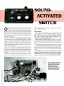
UND ACTIVATED
ITCHES
are cheaper to buy than build
very easy to install!
s
GERNSBACK
PUBLICPTION
How to beat the high cost
of cheap meters.
You get what you pay for.
So get the Fluke 70 Series.
I..ui....l...d..ul
)
,n
You'll get more meter for your money,
whether you choose the affordable 73,
the feature -packed 75 or the deluxe 77.
All of them will give you years of
performance, long after cheaper meters
have pegged their fishhook needles for
the last time.
That's because they're built to last, inside and out. So they're tough to break. They
don't blow fuses all the time. You don't
even have to replace batteries as often.
And they're backed by a 3 -year warranty.
20
Not the usual 1 -year.
Of course, you may only care that the
world- champion 70 Series combines digital
and analog displays with more automatic
features, greater accuracy and easier operation than any other meters in their class.
You may not care that they have a lower
overall cost of ownership than all the other
"bargain" meters out there.
But just in case, now you know.
For a free brochure or your nearest distributor, call toll -free 1 -800- 227 -3800,
ext. 229.
FROM THE WORLD LEADER
IN DIGITAL MULTIMETERS.
....--.
FLUKE 73
FLUKE 75
579'
Analog::;:
\tits.
,
FLUKE 77
..
..
..
;
splay
Volts. ohms. 10A. mA.
bolts. ohms. 10A, mA
test
diode test
diode test
Autoränge
Audible continuity
Audible continuity
0 7% basic dc accuracy
Autorange/range hold
'Touch Hold" function
2000- hour battery
0 5% basic dc accuracy
Autorange/range bold
2000* hour battery
0
ohms. 10A. diode
3 -year
warranty
lice
3 -year warranty
life
3% bask dc accuracy
2000.
3 -year
hour battery lite
warranty
Multipurpose holster
'
Suggested U S list price. effective November 1.1985
Patent pending
FLUKE]
IN
THE U S
AND NON -EUROPEAN OOUNTRIF
EUROPEAN HEADQUARTER,
.
CIRCLE 19 ON FREE INFORMATION CARD
rands4
INCLUDING
12 -PAGE
R
Volume 4, No. 4
._mot
GAD O
April 1987
SPECIAL FEATURES
39
44
59
60
66
68
-a
new life for that golden oldie Little
Use That Old Computer
Printers
Get NLQ From Old
-put that printer back on line
The Arabs Have a Word for lt-a Language Interpreter for PC's
The Cold Virus is in a Bind -what researchers have discovered
Compute dB in Your Head -put the world's first computer to work
Unique Electronics- transform your home into your dream house
Joysticks Trackballs page 63
FEATURETTES
23
73
74
To Sleep, To Dream -fiction or not?
Magic Paperweight -holds on to important documents
Three -mile Hole-to discover more about earthquakes
THEORY AND CIRCUITS
63
34
75
Unique Electronics -page 68
How Joysticks and Trackballs Work -they are a nightmare to repair
Touch Screen Technology-get the feel of it
Electronic Fundamentals-what you need to know about solid -state
components
CONSTRUCTION
26
30
42
61
Touch Light Dimmer-why buy one when you can build one?
Sound -Activated Switches -are not just for turning on lights
Binaural Mikeset -lets you record life -like audio
Test -A -Matic -lets you save on telephone repair
Binaural Mikeset -page 42
SPECIAL COLUMNS
22
84
86
88
90
92
96
Saxon on Scanners -handheld competes with base stations
Jensen on DX'ing- looking to the future
Carr's Ham Shack-the advantages of limited -space antennas
Circuit Circus -homebrew projects that teach as well as entertain
Ellis on Antique Radios- thanks for the memories
Wels' Think Tank -how did you get started in electronics?
Friedman on Computers- software created on the kitchen table
Touch Light Dimmer -page 26
DEPARTMENTS
2
4
8
16
37
47
71
Editorial- there's
nothing new under the sun....or is there?
Letter Box -we respond to your inquiries
New Products Showcase -moves with the marketplace
Bookshelf-what's new in electronics literature
Free Information Card -all you want to know from those who know it best
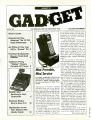
Gadget-the newsletter for grown -up kids
GE mini portable telephone-Toshiba portable CD player -Braun
handheld blender-VP 700 voice messenger and more!
FactCards
storehouse of knowledge at your fingertips
Touch Screen -page 34
-a
Test -O -Matic -page 61
1
INCLUDING
12 -PAGE
GADOSit
EDITORIAL PAGE
Volume 4, No. 4
April 1987
The Magazine for the Electronics Activist!
There's nothing new under the sun, except...
April comes but once a year just as the other months do. Editors sometimes get the urge to do
some special effort on behalf of the spirit of the first of that month and this editor is no exception.
One good ploy was to spoof the time -honored decibel, but John, our budding new editor,
mentioned that we have a hot story on how to figure out dB's without a scientific calculator or
tables. So left Bell's baby alone.
I
The next gimmick came up with was a play on how some exotic language can be learned by
placing an EPROM in a subject's brain. Bob, my main construction man, said that was a bit late.
A company just came up with software and chip to translate Arabic to French and English. In
fact, Bob noted that the program handles the Latin languages without a chip. So down went
another idea.
I
I
So came up with the ultimate idea, a story on a company that makes electronic gadgets do
the work we don't like to do. Herb, my ace troubleshooter, pipes up that read his latest feature
story on how this California ex -pilot converted a hobby into a full -time business; and it wasn't fair
of me to peek at his copy until he finished with the editing.
I
I
had it! had one idea left, and went ahead with it. It's in the issue and hope you enjoy
Should you not spot it, then maybe did too good a job!
Well,
it.
I
I
I
I
I
Julian S. Martin, Editor
Cover photography by
Walter Herstatt
Composition by
Mates Graph: /'
Larry Steckler, EHF, CET
Editor-In -Chief & Publisher
Art Kleiman, editorial director
Julian S. Martin, KA2GUN, editor
Robert A. Young, associate editor
Herb Friedman, W2ZLF, associate editor
John J. Yacono. associate editor
Brian C. Fenton, associate editor
Byron G. Wels, K2AVB, associate editor
Carl Laron, associate editor
M. Harvey Gernsback, contributing editor
Teri Scaduto Wilson, editorial assistant
Ruby M. Yee, production director
Karen S. Tucker, production manager
Robert A. W. Lowndes, editorial
associate
Geoffrey S. Weil. production assistant
Jacqueline P. Cheeseboro, circulation director
Arline R. Fishman, advertising director
BUSINESS AND EDITORIAL OFFICES
Gernsback Publications. Inc.
500-B Bi- County Boulevard, Farmingdale, NY 11735.
516293 -3000
President: Larry Steckler
Vice -president: Cathy Steckler
NATIONAL ADVERTISING SALES
(For Advertising Inquiries Only)
Joe Shere MIDWEST /PACIFIC
1507 Bonnie Doone Terrace
Corona Del Mar, CA 92625 714/760-8697
Alan Berg EAST /SOUTHEAST
11 Manor Drive
Marlboro. N J 07746 212 603 -9510
AIA
Ali
Hands -on Electronics, (ISSN 014329681 Published monthly by Gernsback Publications. Inc.. 500.B131-County Boulevard. Farmingdale. NY 11735 Second Class postage paid at Farmingdale. NY and at additional mailing offices. One -year. twelve issues. subscription rate U.S and possessions $28.00. Canada
$33 00. ail other countries $35.50 Subscription orders payable in U.S. funds only, International Postal Money order or check drawn on a U.S. bank. U. S. single
1987 by Gernsback Publications. Inc. All rights reserved. Printed in U.S A.
copy price $2.50.
Postmaster: Please send address changes to Hands -On Electronics, Subscription Dept., PO. Box 338. Mount Morris, IL 61054 -9932.
stamped self -addressed envelope must accompany all submitted manuscripts and or artwork or photographs if their return is desired should they be rejected.
We disclaim any responsibility for the loss or damage of manuscripts and or artwork or photographs while in our possession or otherwise
A
As a service to readers. Hands -on -Electronics publishes available plans or information relating to newsworthy products. techniques and scientific and
technological developments Because of possible variances in the quality and condition of materials and workmanship used by readers, Hands -on Electronics disclaims any responsibility for the safe and proper functioning of reader -built protects based upon or from plans or information published in this
magazine.
2
Increase your knowledge about all aspects of electronics
An absolutely no -risk guarantee.
&lect.
Books for only $295
5
and get a Free Cift!
TROUBLESHOOTING
& REPAIRING
¡EADINI
SCHEMATICS
SCIENCE
TRICKS &
EXPERIMENTS
AUDIO
1977P. Troubleshooting and Repairing
Paper $18.95
Satellite TV Systems
1503P. Maintaining and Repairing
Videocassette Recorders Paper 515.95
1897P. Beginner's
Repair 3rd Edmon
1536
lues
"ato
$126.75
514.95
2665
1825
$17.95
1553
$15.95
MEKIDS
EIECIRONC
BOX
Trouble-
Paper 514.95
shooting
TRANSDUCER
PROJECT
TV
Paper 512.95
Digital Electronics
1250P.
$15.95
Guide To
3
MEG
EXCITING
PROJECTS
Designing. Building and Testing
with
Your Own Speaker System
Pape $10.95
Projects-2nd Edition
1964P.
2728. Demystifying Compact Discs. A
Guide to Digital Audio
515.95
2675.
Microphones -3rd Edition
$22.95
The Complete Shortwave
Listener's Handbook -3rd Edition
Paper $16.95
2655P.
BOOK
Paper $12.95
Arar
GIANT Book of Easy -to-Build
Paper $16.95
Electronic Projects
1599P.
J
1996
$13.95
(
REFERENCE
& THEORY
Electronic Design and Construction of Alternate Energy Projects
1672P.
1587P
1277P
$14.95
915.95
1586.
25
Projects
Silicon- Controlled Rectifier
517.95
Tables
Master Handbook of Electronic
.ith Fdmon S24.95
& Formulas
1370.
The
1625.
Master Handbook
Circuits
iP,r.,i,he,
ROBOTICS
a
P,,
of IC
526.95
crs Snownr
Membership Benefits
2516
1658
$23.95
516.95
1909P
Big Savings. In addition to this introductory
offer, you keep saving substantially with members' prices of up to 50% off the
Bonus Books. Starting immediately. you will be eligible for
publishers' prices.
Club
our Bonus Book Plan, with savings of up to 80% off publishers' prices.
News Bulletins. 14 times per year you will receive the Book Club News, describing all the current selections- mains, alternates, extras -plus bonus offers and
Automatic Order. If you
special sales, with hundreds of titles to choose from
want the Main Selection, do nothing and it will be sent to you automatically. If
you prefer another selection, or no book at all, simply indicate your choice on the
reply form provided.
Ironclad No -Risk Guarantee. If not satisfied with your
Exceptional Duality. All
books. return them within 10 days without obligation!
books are quality publishers' editions especially selected by our Editorial Board.
1529P 514.95
514.95
UItS
FREE when you join
MUSTER
IC
A Handy, Pocket -Sized
COOKBOOK
1671P
516.91
t
Elementary
Electricity
1632P
l
1665P
$12.95
$17.95
1199P
Resistor and Inductor
Color Code Calculator
$16.95
RESISTOR COLOR CODE
MAMASOUND
RECORDING
BUDGET
ELECTFI III
S
BowK CLUB
P.O. Box 10, Blue Ridge Summit, PA 17214
Please accept my membership in the Electronics Book Club and send the 5
volumes circled below. plus my FREE Resistor & Inductor Color Code Calculator.
billing me $2.95 plus shipping and handling charges. If not satisfied, may return
the books within ten days without obligation and have my membership canceled.
agree to purchase at least 4 books at regular Club prices (plus shipping /handling) during the next 12 months. and may resign any time thereafter.
I
Am.
a--r--i.
2753
623.95
2635
S19.95
1604P
_.
515.95
I
1199P
Of
fUNDAiiICTALS
plltEÇT
cümaw
1587P
i.0
TAE I79PLFIE
MMBS
1250P
1599P
1964P
OSC(LLOSCOPQ
r--11
1977P
1277P
1604P
1370
1632P
1625
1992
2609
19H7
1532P
1665P
2616
1503P
1671P
2635
1529P
1532P
1825
1672P
2655P
1858
2665
1536
1870
2675
1553
1566
1897P
1909P
2728
2753
Address
City
State /Zip
$19.95
1498P
Name
Ef
nal
1870
-
Covers equipment and techniques.
$14.95
2609
$26.95
Phone
Valid for new members only Foreign applicants will receive ordering instructions. Canada must
remit in U.S. currency. This order subject to acceptance by the Electronics Book Club.
RESP -387
ELECTRONICS BOOK CLUB. Blue Ridge Summit. PA 17214
CIRCLE 7 ON FREE INFORMATION CARD
LJLJ
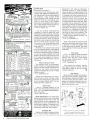
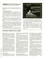
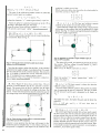
Under the Table
Hands -on Report of the Checkman
Mini Pocket DMM, December 1986, the
author refers to Table 1, but there was no
table in the article! Since the missing
table contains all the results on the
meter, the entire reason for the article
disappears along with the table.
hope you will publish these test results soon, and if there is any way you
could send me a copy of the table before
your next issue, I would appreciate it. I
am considering it as a Christmas present and hesitate to buy a new product
blind via mail order.
enjoy your publication and buy it regularly. I very much appreciate the electronics design computer programs and
the broad range of construction projects.
have an old Timex 1000 computer and
intend to install the TI keyboard as per
your article in that issue.
K.B.S., Lansing MI
TABLE
In
ResistanceMarked Value
(Ohms)
1- COMPARISON TESTS
Value Measured on Resistance Measured
Service Meter.
on Checkman Mini
(Ohms)
(kOhms)
1.01
1
68
10k
150k
750k
910k
820k
I
I
.001
.069
9.95
68.1
9.93k
147k
850k
965k
808k
143
840
965
808
AC Voltage
on Service Meter
AC Voltage
on Checkman Mini
10.2
20.6
31.4
71.3
120.7
145.0
10.3
20.4
31.4
72.6
120.5
144.8
I
Doubled Over
was very dismayed to discover a couple of years ago that the entire electronic
hobby- magazine market had forsaken
non -computer electronics, giving almost
complete devotion to computers, with an
unnatural religious fervor that left all true
technicians out in a cold, unfamiliar
waste land that was once flooded with
projects we could build and use. Computers are nice in their place, but if
they're going to replace all other elecI
tronics interests, who needs them?
I noted with great pleasure the recent
return to constuction projects and non computer articles like in the days of old.
You seem to be leading the pack. I'm
thinking seriously about subscribing
again; however, when received a subscription card it said $28.00 for 1 year.
compared it to the one I'd been sitting on
from last year (in hopes that, soon, corn puters would loose their death grip on
the market) and I did a double take; or
your doing a double take, I should say.
Last years price was $14.00. What's up
besides price and a return to the old way
of doing things?
-B.J., Paris, NY
Well for one thing, we have gone
I
I
By golly, by gosh, by gum; you're right!
Well, there's no use in hiding under the
table (or hiding the table), so here's Table
1 for everyone to view. (Don't be concerned, we sent K.B.S. his copy before
the holidays.)
monthly. So now we are not only one of
the few magazines left in our portion of
market, we are cranking out twice as
many projects as last year! I'm sure an
avid hobbyist (and lobbyist) such as
yourself will find that doubly enjoyable.
pecially aluminum will stop
it
from buzz-
ing.
I've tried everything from changing the
power supply to adding new sensitivity
ranges, and still pick up ferrous metals
like crazy and precious metals hardly at
all
Nothin' But a Hounddog
am trying desperately to construct a
good metal detector that cancels out not
only ferrous metals but also aluminum in
favor of gold and silver, but, due to the
blackout on electronic articles and projects in the computer age, I am having
difficulty finding anything useful. I've
even been buying old dog -eared issues
of the now defunct Popular Electronics
at garage sales.
One of about 10 Bottle -cap Finders
that I've built over the last year (all of
which claimed to be the answer to finding coins and treasure at the exclusion of
all else) is the Hounddog from 1981
Electronics Hobbyist page 32.
The original circuit was very unstable,
ate batteries at an unbelievable rate, and
found iron superbly. But the only way it
would find non -ferrous metals was to adjust it so the piezo buzzer was turned on
all the time then non -ferrous metals esI
Can you help me improve this one or
to find one that really works as advertized: to find "Treasure Not Trash."
-D.A., Key West, FL
If I could make make a cheap detector
for precious metals only, I would cash in
on it (and big) and get that yacht I've had
my eye on! Inductive probes detect
changes in inductance due to metals
particularly susceptible to ferromagnetism (such as iron). This is the kind you
have built. Capacitive detectors, while
capable of detecting non -ferrous metals,
are affected by everything else as well.
The only thing I can suggest is try
alchemy. At least it has not been as categorically denied by science as inexpensive electronic dowsing has.
Silent CoCo
Reguarding your article: Computer (Continued on page 6)
CABLE -TV
VISA
MasterCard
13
WELL MATCH OR BEAT ANYONE'S
ADVERTISED RETAIL OR WHOLESALE PRICES!
o
SINGLE
ITEM
SCIENTIFIC
ATLANTA
UNITS
íD0--UNIRT
PRICE
PRICE
18.00 ea.
29.95
RCA 36 CHANNEL CONVERTER (CH. 3 OUTPUT ONLY)
72.00 ea.
88.95
PIONEER WIRELESS CONVERTER (OUR BEST BUY)
76.00 ea.
92.95
LCC -58 WIRELESS CONVERTER
105.95
90.00 ea.
JERROLD 450 WIRELESS CONVERTER (CH. 3 OUTPUT ONLY)
109.95
58.00 ea.
SB ADD -ON UNIT
Call for specifics
UNIT FOR SCIENTIFIC ATLANTA
BRAND NEW
109.95
58.00 ea.
MINICODE (N -12)
119.95
62.00 ea.
MINICODE (N -12) VARISYNC
179.95
115.00 ea.
MINICODE VARISYNC W /AUTO ON -OFF
70.00 ea.
139.95
M -35 B (CH. 3 OUTPUT ONLY)
125.00 ea.
199.95
M -35 B W /AUTO ON -OFF (CALL FOR AVAILABILITY)
109.95
58.00 ea
MLD- 1200 -3 (CALL IF CH. 2 OUTPUT)
14.00 ea.
24.95
CH. 3
INTERFERENCE FILTERS
18.00 ea.
29.95
JERROLD 400 OR 450 REMOTE CONTROLLER
185.00 ea.
225 00
ZENITH SSAVI CABLE READY (DEALER PRICE BASED ON 5 UNITS)
Please Call
Other products available
SPECIFY CHANNEL 2 or 3 OUTPUT
-
-
-
LOWEST
TOTAL
PRICE
Each
-H
PRICES
ANYWHERE!
Price
Output
Channel
tern
Quantity
-4
.
SUBTOTAL
Shipping Add
$3.00 per and
California Penal Code "593 -D forbids us
from shipping any cable descrambling unit
to anyone residing in the state of California
Prices subject to change without notice
COD 8
Aards
d
Add 5%
-Add
C
TOTAL
PLEASE PRINT
Name
-
City
Address
State
:
_
-_
-__ _
Zip
-
Cashier's Check
Acct "
Signature
i
:
-
-_
_.
Phone Number
-
Money Order
_-
_
-
-
_-
E
-
-_
COD
I
I
[
]
Visa
Mastercard
Exp Date
-
FOR OUR RECORDS.
-
I. the undersigned. do hereby declare under
DECLARATION OF AUTHORIZED USE
penalty of perjury that all products purchased, now and in the future, will only be used on cable
TV systems with proper authorization from local officials or cable company officials in
accordance with all applicable federal and state laws
Dated
-
Signed
Pacific Cable Company, Inc.
73251/2 RESEDA BLVD., DEPT. H -4
(818) 716 -5914
No Collect Calls
RESEDA, CA 91335
(818) 716 -5140
IMPORTANT: WHEN CALLING FOR INFORMATION
Please have the make and modela of the
e' ui r ment used in our area.
an
"ou
5
ULTRA -MINIATURE
_ye
5 VDC RELAY
I
LIGHTED
ROCKER SWITCH
y
ruptsu
a OR211NED005M20
H. n sensmv4y
C OIL 120ohms
yv
LETTER BOX
(Continued from page 4)
Controlled Voice Synthesizer (December 1986 Hands -on Electronics),
can't figure how to connect this project to
my computer.
have a Radio Shack
Color Computer II 64K. Please, can you
help me? As this is a very popular computer I'm sure many of your readers
would also be interested in this modification. have already acquired all the necessary components, need help!
'
'I
snap mpur,'
$1.25 each
O
10ór$10.00
l.
ro
I
'
o,,.
n
í15.a, I.ghteu
e
range ens
16
arm,
comae
CONTACTS
amp
Mounts in 14 pn DIP socket
1
St 50
1
MINIATURE TOGGLE SWITCHES
I
ALL ARE RATED 5 AMPS © 125 VAC
I
S.PD.T.
S.PD.T.
(on -on)
S.PD.T.
(on -on)
PC style
non threaded
(on- off -on)
Solder lug
lermmals
51.00 each
Soroer lug
,,
ousmng
755 each
10 for 57.00
t0 rorf9.00
loo Ior $e0 00
-R.M.T., Winder, GA
terminals
51.00 each
io er$g 00
100 Ior $80 00
r
13.8 VDC REGULATED POWER SUPPLY
4-
These are Soll, slate fully regulated[I 8.ac.
power Supsbes Both t eualure 100°= sona slab
construction. ruse protection. and L E D powe
.1a
///h/////p
/////////////
/ Indicator
.
I
PXs
M
ß'ti
:
-0
U L
listed
2
amp constant, a amp surge
$20.00 each
3
amp constant.
$2750 each
amp surge
5
COMMODORE PRINTER /PLOTTER
Commodore Model 1520
Four color
plotter Standard VIC
serial interlace allows easy connection
to Commodore 64 computers Up to 80
characters per line )upper and IOwer case)
In tou, sizes
CAT COM -1520 $49.95 each
a
X
,--_
_
I
,
EXTRA pen sets 51.50 per set.
-t-
COMPUTER
GRADE
CAPACITORS
2.000 mid. 200 Vdc
'
-nigh
S.
6.400 mid. 60 Vdc
'
19 . 334' nigh
$2 50
9,700 mid. 50 Vdc
t
r.5
13E
.4
1'2" high
i
00
5
31,000 mtd. 15 Vdc
134 "r 4 -hgh
5250
50.000 mid. 40 Vdc
$4 50
3-.534 "high
66,000 mid. 15 Vdc
3' %334 -ngn
$300
60,000 mid. 40 Vde
3'.5 "hgh
5350
86.000 mid. 30 Vac
EDGE
CONNECTORS
ALL ARE .156 SPACING.
9L LCQCDNLwtlrL.iLC
-s.
-
, FFFFF ,INr,r
-
22 EDGE CONNECTOR $1.25 ea
+ Noer lug Style
to for 51100
22/44 EDGE CONNECTOR
$2.00 ea PC style 10 for $18.00
22/44 EDGE CONNECTOR
solder lug style
$2.50 each
28/56 EDGE CONNECTOR
$2.50 ea PC style 10 for $22.00
36/72 EDGE CONNECTOR
PC style
y
53.00 each
43/86 EDGE CONNECTOR
,c
$4.50 each
r
TI SWITCHING POWER SUPPLY
COmpaci well.regulated swacrhng power supply
designed to power Texas lnstrunten s computer
equipment
INPUT
14 - 25 vac @ amp SPECIAL
12 vdc(a35oma
OUTPUT
\
+,-
1
12amp
5vOC
SIZE
-5vac
4'.
PRICE
C. .1'. ngn
x
-
$3.50
200 ma
6,21 it
each
RECHARGEABLE UNIVERSAL CHARGER
NI -CAD BATTERIES
-.'$185
AAA SIZE
AA SIZE
AA
.
.
SIZE
C
.
5Út3-C SIZE
D
SIZE
- $1.85
$2.00
'
$3.50
.' $3.50
$3.50
.;
I
STANDARD JUMBO
DIFFUSED T1 3 /4
10 for S1. ad
100 for $13.00
RED
10 for 02.00
GREEN
t001or 51700
YELLOW
100fo,,riióó
LED HOLDERS
Two p,ere holder
l ED
10
for 655
ea
100 tor 55.00
TELEPHONE
COUPLING
TRANSFORMER
TTPC8 or
Stand, a
1Iad Tv304
P
600 ohms c
lo 600 ohms c
P
board mourn
GAT.
1C11
n
<
. 51e
y.
r
_
fie
:ill
t
10 AMP SOLID STATE
RELAY
E
I
,
mother -in -law before she shaves.
Thanks for being what you
hobby fun -book!
-H.Y., Hollywood, CA
are-a great
Thanks for expressing your enjoyment of Fred the Head. I bet your moth er -in-law is a lovely person, and the two
of you are great friends. With Fred the
Head you'll have a great trio.
I
All you really need do is wire the extra
digits as in the article, and if more current
is required to charge the battery, hook
further solar cells in parallel. We would
do an addendum if only it wouldn't sound
redundant.
Text Tease
on page 22 of the December
'86 issue, no value is given for L2. InIn Fig.
1
stead it says "see text," unfortunately
the text says nothing about it. What
should the value be?
-D.S., Tallahasse, FL
Sorry about the "inductor, inductor,
who's got the inductor ?" game. It should
have been printed as 2µH for the described frequency.
Get Sassy!
All you wonderful readers that send us
mail, be sure to include a SASE (that's
self-addressed, stamped envelope-not
a call for chaos) with your letters. That
allows us to quickly respond to your requests for information, whether they appear in this column or not.
-a
read in "Computer Basics'
Life
book -that PE's (Popular Electronics)
arch rival was Radio Electronics!
didn't know that.
-M.B., New York, NY
I
I
r six
L`tt
`
59 50 EACH
10 FOR
590.00
PHOTO -FLASH
CAPACITORS
.T e'
70 ml 330v
75c ea.
t
CAT. PPC -170
,
Cu
1
400 ml 330v
1.00 ea.
CATO PPC400
800
CAT
nut
PPC -800
TOLL FREE ORDERS
1
.800-826-5432 Oa
(IN CA: 1-800-2584666)
INFO (213) 380.8000
WX - 5101010183 ALL ELECTRONIC
6
What a Head on Fred!
The January cover is the greatest.
Fred the Head is an exceptionally good
project, but what a head! It looks like my
That's Life!
barge 4 AA C D or AAA
cads or one 9 volt m cad at
IO e10e 511.00 per charge,
III
Si 25
each
--
-
I can can certainly understand the
frustration of trying to adapt the Voice
Synthesizer to your particular computer.
However, its really quite simple: First get
a copy of your computer's parallel printer
t O port connections. Then. as stated in
the article, wire a cable to connect like
bits: A1, to Al, A2 to A2, and so on. Or, as
in my case, Al (on the synthesizer) to bit
1 of the computer, A2 to bit 2, and so on
down the line.
However, if your computer has a serial
port, you have two options: either devise
a circuit, most likely using a UART, to
convert the serial port signal to parallel:
or, you can simply redesign the circuit
board to accept serial port data at pin 21
of U1 (see pinout diagram of the synthesizer chip). Well that about covers it.
Good luck!
presented in the easy -to- understand,
detailed fashion of Solar -powered
House Numbers. Congratulations to the
author and the editors for the selection of
it However, how many houses are numbered with just two numbers? In my metropolitan area, four numbers are
common, and five not uncommon. What
a practical device this could have been
for police and fire assistance. How disappointing to find this an apparent classroom exercise without much practical
application. How about an update article
and circuit for displaying at least four
numbers. Or do we have to build separate units for every two numbers? Get
that addendum to this article coming!
Keep the good articles coming. do
enjoy the magazine.
-C.H., Coral Gables, FL
330v
1.35 ea.
MINIMUM 000111 E000
E
USA 5300 SNIPPING
No c D
E011E,GN ORDERS
INCLUDE SUPEICIEN
sNIPPpNc
CALLE
ES
AO
CIRCLE 8 ON FREE INFORMATION CARD
6
r
e
Radio Electronics is our sister publication and the editors never considered
any magazine an arch rival. In fact, the
editorial staffs of those magazines met
frequently at press conferences and
broke bread together. Sometimes writers let their imaginations run away from
themselves when they recall history.
Enlighten Me
highly encourage the editorial selection of more articles developed and
I
6
n/t7.SOh
/ kfOlt' 1(Il are a
,Qe'lliU.h,llll' Muster,
but the computer printout .5enS
Melvin shouldn't have eleven tues.
C
C
O
I
T
E. F.
N
O
OK MACHINE MfiWC NC!OINTERSILÁO
SAC. INC. J. W. MILLER AAVID ENGINE!
VISA
'
C
_
erg C G
R P O R A
JOHNSON ATLANTIC SEMICONDUC"
'
AK P..n.to Rico
256K 1262,144
NfW '
OpOCMOS
SOLDER TAIL
DIP SOCKETS
12060111.7
.
.
FAX
52e77914
218-
$5.7011; $39.9519
DRAM 150NS
x 1)
MFlak
6%Crbon Film
TANTALUM CAPACITORS
DISC CAPACITORS
w
e
t
'
....
WIRE WRAP
..
....
-
701111 C140401 MN OP
6111.
GM.,
10 OAT. GAN
..
.
^IIII
I
A
w.,t
A
0u.
..
A
f..
ra
N
7
co
.
_
...
.
.
.
y
.
.
.,,
n
o
Metal Film Fitted Re..to.e
°
o,..
.
I
1%
14
.
e100
..m
001.0.
111.1074.11511011S Gomm
..
o0
SID
7""M .w
...,....,... ..,.......,, _,.
DIP SOCKETS
e.........
.
.
..o.+n,ro.
..m
.
,
"
'
6 2110
.. ..
.....
.
...
IVA
..._..
1
ESDECWINDSOTRESAMDEKGG.E.
cr
,.,
IIII
9103508982 DIGI KEY CORP
TWX
8ß1.11N
iGAR YAGEO J. W. MILLER LUXO
PLESSEY
ARIES
,C CHEMICALS
Factory Firsts
I,.
MD. .W
T.I. .
218 681 ßR11
MEIMECMEM
INTE{RA7\DC711CINß{
INTEGRATED CIRCUITS
.7403 171
1- 800 -344 -4539
/
,
n
.Ye
..
..
A r
24.1
110DISC
CAPACITORS
'
-
a
NO
0
.
PANASONIC LS SERIES
we. wAa
eata
.
..e-s a
016
.
.
'
,.
W
0
....
..
G
... ,.,..n,,..n,.n..
,,
,
-
2 7
..
°
_
....
..
.
.
®
11116
w .A
.
N
,
.11 1. 041.10.0.
,®
,ar
m
1
.
e.na.
^.
...w
.a.
.A.
'540S
AUG
.wm
.
....
.
,.,
,a,p
:
.
A
A
.A.
ADO
.
44
4
a
A
0
06
--0111.)7
,
.'.
..
,
i.,,,.
U
1
A
1)
1
A
.
.
1e]
au so
OW
07 50
.
1
Ol
4.
'1..
IA
w
w
..
r.
.
"-
,
...
..
A
..
,
UA
..
.
.
.
.
.n7.W.r~M
'
.
.nf
11
1
IA
14
r.
S2
43
1113
732 73
03
A
OD
61 0
-
.
,
i
e
(-A I.
0
2
.
fJ495
PANASONIC V SERIES
10 40
n....~
vr.
.....
.,-.
,
m.
'
'
,
.
-
..
w.
"
AMP SILICON RECTIFIERS
rt,i.7,1',I,tU
A
ór
,wV.rnm..n.0w
4 On
..
-.
.
...
,
G410 4776A'
do co
.
,
... ....
...
m.
.tl -llpen-
nA
.
10
P7ldeMi
üülíI
-
.
.
.
.
..
.....w
..
,
.
'
03a
. .,,,
..
...
...w.
.
..
.
.
,
.
.
.
.
.
+n
.
.
-... ñ".
.opra:aasa
NEC M-
.,......
..
..
.
,.
...
...
tnl
I
ChiPS
,
0
AMP SILICON RECTIFIERS
OW000
}1
iJ
1
.,
Z
375
210
Y
....
-
....
,.
.
...,
01
10
,,.
A
12
6
N
..
110
e
.10
.
a.
.vs
.
...
o..
A
.
,n
,
,
,
.
07
T1wDIPReT.aalwa.I.1.R.a..1i.ed,.9.k,wm.PPrMal,.nwkmeYD.PIC.Y,.wYO.toro.n.o1P...w,..wown, na.wIwt...b,a..o,.,t.a...,e.,lm.ewtlw.,n,.
ND bloomy pe p.11 mn0... AM, na.yvow mar. loos .l W aw Owcwnwal. dn. w apply Me .W,oP... dncoont To Om .,SlOwl, aad ow ron dnounetl. n... Tom .a im eerxce
d,.P. W. pry M dppoy.,0..wnRe to mama. e. the U S. A, Canada and Ma.w.Nwn chock at own, ad. pompoms cwt. Dg. Key Wy a5.pa ...mom tho cmww,.W U S. MM.,
Nweli.ClneOe and W.co
1117I1.
UNIR ORMRNC I1 PRORE. CALL TIN -718M71 All. FM 714611 M241. RI NAR WOO 201111 ORDER TO: KIKI-KIT. P.O. Ml 077. Thiel lbw F.W.
be replaced w Muro
Too mry Py by IYwck, mwwY wdr, Mn1. Cllnpe. VISA o. C 0 D ONFXET OUAAANTE(: Any Ina o. wOdu, n WnNad non. DV Key oat Pop. to Iw M.o1.a .A
r\
CIRCLE 13 ON FREE INFORMATION CARD
NtY
....
n.etJ
, 72
'39y
74
._.
am
.
SERVICE CHARGES VOLUME DISCOUNT
NET
0.N-1 99.99
Add 12.N
1 LNJ \.N
F
1\.10.1Ó.N
Ó.MBN.N
1
N.I{M.N
LIP
Add 00.75
Add N.50
Add N.26
No CharP
1100 .00 -1249.99
1
s
250.001199.99
SN.04Nß9.N
1/000
8
Up
Le..
10'/.
Leu
25Y.
L.
154
Le.. 20'/.
7
D
J
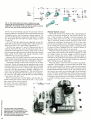
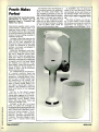
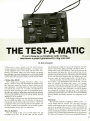
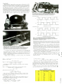
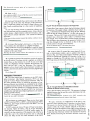
Driving Driver
If
you thought the car loudspeaker
couldn't get more complex, then the
Mobile Sound Division of Nakamichi has
something to change your mind. The new
driver designated the SP-40 -uses a 10-
-
cm, carbon- graphite reinforced. polypropylene main cone, with a mechanical
crossover to a 4.3 -cm, high -frequency
subcone. Special care has been taken in
designing the magnet structure and cone
configuration to ensure natural reproduction of the entire audible frequency range.
The compact dimensions of the new driver-especially vis -u -vis depth-permit it
to be installed in the door frame of most
cars very easily. Thus, the SP-40 can be
used both as a full -range speaker for low cost installations, and as a bass /midrange
driver in two -way systems where the
Nakamichi SP-50 might not fit.
noticeably more musical. The copper cap
also reduces voice -coil inductance and so
produces uniform impedance into the
high- frequency region. That permits the
speaker to draw the same power from the
amplifier at all frequencies and results in
an unusually broad and uniform frequency response.
The SP-40 retails for $115 per pair. For
ordering and sales information call
800/223 -1521 inside CA; and call
800/421 -2313 from all other states.
angle making each and every disk visible.
The fliptop lid features a carrying handle
and latching mechanism which provide a
dust- and moisture- resistant environment.
It retails for $19.95. For further information, or to place an order, write or call:
M & R Distributing Co., Inc., PO Box
190. Oceanside, NY 11572: Tel.
516/678 -3334.
Static -Control Floor Finish
If you work with CMOS chips by
yourcompany then your ESD
problems could disappear with the your
next floor resurfacing. A new video tape
describing the use and application of
Statguard Floor Finish. an alternative to
floor mats and tiles for eliminating ESD
self or for
a
problems. is being offered by
Charleswater Products, Inc. of West Newton, MA.
The Statguard Training Video Tape features a demonstration of the proper application of the conductive floor finish for
a complete ESD program. Covering approx. 2,000 sq. ft. per gallon. the highgloss floor wax dissipates static charges
and prevents further charge generation
from walking for up to 60 days.
CIRCLE 65 ON FREE INFORMATION CARD
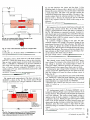
Polypropylene is immune to the heat
and humidity experienced in a car. and it
has excellent damping to prevent the ringing, harsh sound that characterizes other
environmentally safe materials. The poly-
propylene is reinforced with carbon graphite fibers that add negligible mass,
have no effect on damping, but do
strengthen the cone to prevent cone breakup and the resulting sound coloration. The
cone is suspended by a urethane surround
that suppresses edge vibration and per-
mits long-throw motion for powerful bass
reproduction.
In the SP-40, eddy-current distortion
has been virtually eliminated by shielding
the center pole of the magnet with a copper cap. Eddy -current flow is thus confined to the low- resistance copper cap
and, since current flow in copper is inherently linear, the composite magnetic drive
is linear as well. As a result, high -frequency, third -harmonic distortion is drastically reduced and the sound is
8
CIRCLE 63 ON FREE INFORMATION CARD
Super Disk -Filing System
Some spend time trying to develop a
better mouse trap -making a good thing
better-and M & R Distributing has made
disk filing excellent with their 5 -W "Pic A- Disk" system.
That system is a major improvement in
disk storage. The unique design and color
coding of the disks and the residential slot
feature, make instant disk retrieval, identification, and replacement a reality.
Pic-A -Disk also serves as a filing system and organizer, thereby eliminating
the possibility of misplacing a disk. It is
now virtually impossible to misfile disks
when using the patented color-coded system.
Pic -A-Disk holds and stores 50 disks in
a desktop storage tray at an easy viewing
CIRCLE 75 ON FREE INFORMATION CARD
Complete with maintenance procedures and ESD measurement tips for
the UL- classified antistatic floor treatment, the Statguard Training Video Tape
is available in popular VHS and Beta formats. Playing time is approximately eight
minutes. The Statguard Training Video
Tape is available on loan, at no charge.
(Continued on page /2)
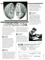
Train with NRI for a high paying
career servicing computers.
SANYO COMPUTERCPU double-sided disk drive,
256K RAM. 4.77 MHz and 8
MHz turbo speed.
DIGITAL MULTIMETERProfessional test instrument
for quick and easy
MONITOR -High resolution,
green screen displays, crisp
text and graphics.
TECHNICAL. MANUALS
-with complete specs on
Sanyo computer and
professional programs.
measurements.
-
LESSONS Clear, well illustrated
texts build your understanding
of computers step -by-step.
DISCOVERY LAB -Using it,
you construct and test
circuits hake those used
with computers.
-
DISK SOFTWARE
including MS-DOS. GW
BASIC, WordStar.
and CalcStar.
DIGITAL.
LOGIC
PROBE
-
Simplifies
analyzing digital
circuit operation.
Get started now by building this
fully IBM PC compatible computer
Now you get it all ... training for America's
fastest growing career opportunity ..
training to service all computers ..
training on the newest total computer
system, the Sanyo 880. Only NRI can give
you the well- rounded training you need,
.
.
because only NRI gives you a complete
computer system
computer, monitor,
disk drive, software, even test instruments
like a digital multimeter and logic probe to
work with and keep. It all adds up to
training that builds the knowledge,
competence, and ability you need to
succeed as a computer service specialist.
.
Get inside the newest, fully IBM PC
compatible Sanyo Microcomputer
As an NRI student, you'll get total
hands-on training as you actually build
your own latest model Sanyo 880 Series
computer from the keyboard up. It's fully
IBM PC compatible and, best of all, it
runs programs almost twice as fast as an
IBM PC. As you assemble the Sanyo 880,
you'll perform demonstrations and
experiments that will give you a total
mastery of computer operation and
servicing techniques. You'll do programming in BASIC language-even run and
interpret essential diagnostic software.
Understanding you get only
through experience
You need no previous knowledge to
succeed with NRI. You start with the
basics, rapidly building on the fundamentals of electronics with bite-size lessons.
You perform hands-on experiments with
your NRI Discovery Lab and then move
on to master advanced concepts like
digital logic, microprocessors, and
computer memories.
Learn at home in your spare time
You train in your own home at your own
convenience, backed at all times by your
own NRI instructor and the entire NRI
staff of educators and student service
support people. They're always ready to
give you guidance, follow your progress,
and help you over the rough spots to keep
you moving toward your goal.
100 page free catalog tells more...
send today
Send the postage-paid reply card today
for NRI's 100 page catalog that gives all
the facts about computer training plus
career training in robotics, data communications, TV /audiol
video servicing, and
many other fields. If
the card is missing,
write to NRI at
the address
below.
MCHOOLS
McGraw -Hill Continuing Education Center
3939 Wisconsin Avenue
Washington, DC 20016
If 1'1
We'll give you tomorrow
Ì}Ig
11
For more information contact:
Charleswater Products, Inc., Pauline
Bendana, Marketing, 93 BorderSt., West
Newton, MA 02165; Tel. 617/964 -8370.
cc
!. °?
--
be used in converters capable of I- to 5-
million conversions per second. The actu
conversion rate will be a function of the
other components in the converter. The
combination of CMOS technology and
tight design rules keep the current con
sumption very low. With a 5 -volt supply,
and at MHz, the device will consume
less than 100 RA; and at 25 MHz the
current increases to less than 4 mA.
Although the part is mainly used in A/
D converters it also has applications in
ring counters and serial -to- parallel converters.
The Zy25HCTO4 is available in chip
form and in plastic, dual in -line packages.
The price for the chips (100pc. price) is
$4.80 and in plastic DIP it is $5.50. Write
or call Zyrel Inc., 1900 McCarthy Blvd.,
Suite 201, Milpitas, CA 95035; Tel.
408 /433 -0488.
.-2
CC
e-°°
0
,,_0,
_
-Oa
NC
°
-°
--e
Ott
ono
`-°
09
__ `
Oa
O7
s
NC
-°
0-6
°
A,t,i
° "°
`
"`n "`
°
CIRCLE 74 ON FREE INFORMATION CARD
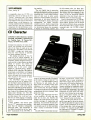
35 -MHz SAR Chip
Our technolog) is speeding up our lives
every day, so it comes as no surprise that
technology is speeding itself up to meet
the demands of we electronics- minded
people. A good case in point is the highspeed successive approximation register
(SAR) produced by Hirel Co. as a direct
replacement for the 2504 and 25L04 bipolar devices. Developed on 1.5 micron nwell technology, the chip consumes less
than 4 mA at its guaranteed maximum
operating point of 25 -MHz.
The Zy25HCTO4 SAR is primarily
used in analog -to- digital converters. With
its ability to be clocked at 35 MHz, it can
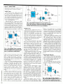
10-MHz Sweep /Function Generator
If you're a test -bench equipment nut.
then hold onto your hat! The LFG -1310 is
a feature -packed sweep /function generator designed for a variety of research and
development, service, design and educational applications. Outputs include every
required waveform: sine, square, triangle,
ramp. and pulse.
Five different operating modes enable
the LFG -1310 to be used as a source for
Solderless Breadboard
Adjustable temperature
range of 150 ° -420 °C
(300 ° -790°F) Grounded
Overheat protection with
closed loop temperature
control Heat resistant
soldering iron cord
Auxiliary ground
terminal Built-in tray
with cleaning sponge
Improved circuit design
for greater temperature
stability
The perfect breadboards
for circuit designing,
testing electronic devices
and educational uses
Red and black binding
posts included for easy
voltage connection 4"
(W) x 8W' (L) x °/:' (Dl
#21 -147
This model is equally at home on the test
bench or in the classroom. Features: High
brightness CRT Alligator clip test leads
External sync input Carrying handle 90
day warranty See MCM Catalog #14 for
Tenma
Compact DMM
3'
1
Terms:
$2995
(ea. j
.sio minimum
1
t..r
$2995
,
c aI
111-11.
oc Poter
lea
... ,.
was SWAT
swnr
AIM litaf:ap
Vila
Rocket General
Purpose 9V Battery
-.11111111111111111
Zinc chloride dry cell
Minimum order quantity
Hisayr
of five
#29 -300
4575 91
38co_ttp(
Be Sure To Call For
Your FREE
Catalog!
Over 7.000
Items!
Year
Limited Warranty
order. SI 00 charge for orders
*Orders shipped UPS C O
orders shipped within 24 hours
sales office open 8 30 am to 700 pm
Saturdays 10.00 am to 300 pm EST
For prepaid orders add 52 75 for shipping
and handling
Should shipping and handling charges
exceed $2 75. the balance due will be sent
COD
both general and specialized measure ment techniques such as frequency re
sponge analysis, noise-reduction circuit
work, and loudspeaker testing. Versatile
output controls enable all types of signal
conditions to be established including different bias levels for amplifier work. The
output may also be frequency or amplitude modulated by an external signal.
The frequency range starts at .01 Hz
and goes to IO MHz in 9 overlapping
steps. The distortion on the sinewave up to
50 KHz is less than 0.5 %; beyond that its
25 dB or more down from the harmonic.
The squarewave rise /fall time is less than
25 ns at maximum output.
The output modes include CW, sweep
(linear or logarithmic from I ms to 10 s),
gate, burst, and trigger with a variable
trigger point.
The unit retails for around $1100 dollars, and to find the number of the Leader
#72 -280
$1588)
under $10
12
CIRCLE 76 ON FREE INFORMATION CARD
#72-300
520 minimum charge card order
VISA
o
Output. Regulated 13 8VDC ',Input:
Fuse protected Heavy duty
binding posts Output current: 5 amp one
minute on, three minutes off; 3.5 amp
continuous
-
more information
"t
Tenma 5 Amp
Regulated Power Supply
1
#72-060
tw'!"
80
7(10
-up)
91
digit shock mounted
display Five DCV ranges
Five DCA ranges Two
ACV ranges Five
resistance ranges
Mohm input impedance
---- - -- -
800/645 -5104.
Tenma 6.5MHz Oscilloscope
$44180)
3
$
.
120VAC
Tenma Soldering Station
s191M
--
distributor nearest you
Attention Electronic Enthusiasts!
#72 -340
`
olio a
I
E
54995
¡i
al
Call Toll Free l-800-543-4330
IInOha 18D7624315
Nirall 18018581849
I-1r.;:
t
"I=
\k`
In A/asaa and
Vio*,
MCM ELECTRONICS
858
E. CONGRESS PARK DR.
CENTERVILLE. OH 45459
A
PREMIER Compony
CIRCLE 20 ON FREE INFORMATION CARD
1987, MCM Electronics
SOURCE NO. HO -01
I
A robot is a robot is
a robot... was a robot.
' Intil HERO 2000.
fhe fourth law of robotics
A robot shall make
learning fun for man
and thereby improve
the quality of life
for mankind.
more tha ¡I a
robot. It's a walking, talking 16 -bit
omputer. With 64K ROM and 24K
Afejua
RAM expandable to more than half
a megabyte. And a fully articulated arm with five
axes of motion. Yours to program. Command. Modify
and expand. Total system access and solcerless
experimenter boards prov de almost limitless possibilities. Its remote RF console with ASCII keyboard
gives total control. Available with three self -study
courses. Backed by Heath Company, world leader
,.
in electror is kits.
?
r
own
Build your
HERO 2000 is much
-
~
HERO 2000. Or
buy
it assembled. Have
fun learning skills
that translate
directly to the
world of work.
w
trie
builcJer
Mail coupon today tc receive a FREE
Heathkit Catalog tea'uring HERO 2000.
Mail to:Heath Company
Dept. 107 528
Benton Hartor, Michigan 49022
FREE. Send toca.
for latest Heathkit Catalog.
Name
Heathkit®
Heath
Company
-
Address
City
Zip
RO-141
th Electronics Corporation
'
"
State
INFORMATION CARD
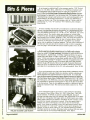
Test and Re -wire RS-232 Interfaces
If you're tired of fiddling with wires for
your break -out box then B & B may have
just what you want. The MAB Budget
Break -Out Box has all the necessary features to open signal lines, monitor
RS -232 signals, and re-wire lines.
Nine 2 -color LED indicators monitor
transmit data, receive data, request to
send, clear to send, data -set ready, carrier
detect, and data -terminal ready. And two
additional LED indicators are spares for
testing any signal line. LED's turn green
CIRCLE 62 ON FREE INFORMATION CARD
for "high" (space), red for "low" (mark)
and off for "open ".
The MAB Budget Break -Out Box performs all the functions of more expensive
models, but the open -frame construction,
only 4" x 3 ", keeps manufacturing costs
down, and the savings are passed on directly to the customer. The retail price is
only $59.95, which includes one male
and one female RS -232 connector. The
unit does not require AC power or bat-
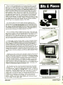
nient electro- plating capability for such
applications as scientific and engineering
development, electronic repairs, specialized production, dental work, special
art-work, and restoration. Completely
self-contained and portable, it is equally
useful in the lab, office, or shop. Utilizing
special disposable cartridge -pens (13 in
all), the system permits an instantaneous
selection from a wide variety of plating
possibilities without the necessity for expending time, effort and expense in preparing a special plating solution. Above
all, it is simple to use with no special skill
required!
A complete selection of pens is available for a wide variety of plating requirements. Power can be supplied by your
own variable D.C. supply capable of supplying up to 12 volts at 0.1 amp or our
variable voltage power supply.
The various pens, power supply, absorbents and such can be bought separately,
unless you would prefer a kit consisting of
the power supply, connector cables, and
the following pens: absorbent, silver, gold
(24K), nickel chrome color, and copper
for $325. Available from Hunter Prod-
Co., 1500 Boyce Memorial Drive, Ottawa,
IL 61350; Tel. 815/434 -0846.
CIRCLE 70 ON FREE INFORMATION CARD
Plating Pens
If you're looking for a way
to electrop-
late your card edge connectors, phono
plugs, or whatever, with gold for high
conductivity, then you may find this system appealing. It has been developed specifically to provide a simple and conve-
trol.
Additional to the light output, is an
electronic output coincident with light
pulse timing that can be used to trigger
other equipment, such as an oscilloscope.
The generator runs for $8250 (fob
Berkeley, CA), from Berkeley Nucleonics
Corp. 1198 Tenth St., Berkeley, CA
94710; Tel. 415/527 -1121.
ucts, Inc., 792 Partridge Drive,
Bridgewater,
08807; Tel.
NJ
201/526 -8440.
CIRCLE 72 ON FREE INFORMATION CARD
Anti -Static Caplugs
.k
teries.
Write or call for more information on B
& B's MAB Budget Break -Out Box
Model 232MAB and a free B & B catalog, at B & B Electronics Manufacturing
ment's light intensity under constant con-
CIRCLE
71
i
s
IIIa-
r
'1¿
ON FREE INFORMATION CARD
Light Pulse Generator
You high -tech optical wiz's will love
this new pulse generator designed to trigger external equipment. The Model 6020
is a fast light -pulse generator with built -in
power metering. It brings to the ElectroOptics field a means of controlling light
with a precision and ease unattainable
previously.
The 6020 operates at frequencies over
250 MHz, has half-nanosecond risetimes,
and generates impulses 500 ps wide.
Basically, the 6020 converts electronic
signals into light. The user can vary pulse
delays and widths, generate single or double pulses, externally trigger or modulate
the light output, determine optical output
power, and more. The instrument serves
as a low-jitter, calibrated light source that
digitally displays pulse baseline and peak
power level, both adjustable with 0.1%
resolution. It employs special control circuitry to provide the user with a stable,
high performance optical generator. A
laser diode is the internal light- emitting
source. The laser-generated light is steadily monitored and regulated with sensing
and feedback circuits that keep the instru-
What good is it to build a static -sensitive project with great care, only to have
it ruined by a static discharge entering
through an unprotected connector? Well,
there is a two -page, illustrated product
bulletin (AS -986), presenting new antistatic connector caps and plugs for both
electrostatic discharge (ESD) and physical protection that has just been issued by
the Caplugs Division of Protective Closures Co., Inc.
The bulletin describes the Series EC
Caps and Series EP Plugs as being molded from pink, anti -static, low- density
polyethylene #78. The material, according to the bulletin, gives excellent ESD
protection and is compatible with clean room processing of components as well.
Anti -Static Caplugs meet the static -decay
test requirements of MIL-B- 81705B.
Specifications, accompanied by dimensional drawings, show that the Series
EC Caplugs are available to cap nominal
thread sizes from %" through 3 ", and that
the Series EP Caplugs will plug listed
thread sizes from 1/2"-28 through 2- V2 " -16.
A price list for standard carton quantities
and for anti- static, poly- bagged "Mini
Paks" containing %s the full carton quantity is included in the bulletin.
A copy of Product Bulletin AS -986,
together with a free sample- assortment of
the new Anti- Static Caplugs, are obtainable from Caplugs Division, Protective
Closures Co., Inc., 2150 Elmwood Ave.,
Buffalo, NY 14207.
Where's Your ELECTRONICS Career Headed?
The Move You Make Today Can Shape Your Future
Yes it's your move. Whether on a chess board
or in your career, you should plan each move
carefully. In electronics, you can move ahead
faster and further with a
B. S. DEGREE
Put professional knowledge and a COLLEGE
DEGREE in your electronics career. Earn your
degree through independent study at home,
with Grantham College of Engineering. No
commuting to class. Study at your own pace,
while continuing your present job.
The accredited Grantham non -traditional
degree program is intended for mature, fully
employed workers who want to upgrade their
careers . . and who can successfully study
electronics and supporting subjects through
.
Independent Home Study Can Prepare You
Study materials, carefully written by the Grantham staff for independent study at home, are
supplied by the College, and your technical
questions related to those materials and the
lesson tests are promptly answered by the Grantham teaching staff.
Recognition and Quality Assurance
Grantham College of Engineering is accredited
by the Accrediting Commission of the National
Home Study Council.
All
lessons and other study materials, as well as communications between the college and students, are in the
English language. However, we have students in many
foreign countries; about 80% of our students live in the
United States of America.
INDEPENDENT STUDY, AT HOME
H-4-87
Grantham College of Engineering
10570 Humbolt Street,
Free Details Available from:
Los
1
Alamitos, CA 90720
Please mail me your free catalog which explains your
B.S. Degree independent -study program.
Grantham College of Engineering
10570 Humbolt Street
Los Alamitos, California 90720
Name
Address_
L
City
Age_
-
.
State
-
Zip
J
15
1
-2 -3 Macro
Library -2nd Edition
By David Paul Ewing
Holy Marco! Most users guides give
you information on the software, but
how many give full -length, ready -torun macros? Well, 1 -2 -3 Macro
Library offers a collection of macros
that will decrease the time spent in
creating, changing, and printing
worksheets. More complete than the
first edition, the 2nd Edition is
designed for all -2 -3 macro users,
including Release 2 users.
1
Desk Top Publishing From A To Z
By Bill Grout. Irene
Athanasopoulos, and Rebecca
Kutlin
As a desktop publisher, you can
create your own newsletters, catalogs,
conference brochures, news releases,
and more. But how do you get started?
Ironically, by reading what someone
else has published!
Desktop Publishing From A to Z
helps you choose the software,
equipment, and procedures you need
to achieve professional results. You'll
find out about software and
hardware-from project- management
programs, to page -makeup programs,
from the Macintosh and the IBM PC,
to the LaserWriter printer. With the
book, you'll learn how to establish a
publishing plan; control costs and
profits; handle printing and binding,
and promote and distribute your
CIRCLE 85 ON FREE INFORMATION CARD
Ready -to-run macros can be
immediately applied to existing
worksheets or modified for specialized
tasks. In addition, users will find
valuable hints for creating and
applying their own macros to I -2 -3
spreadsheets, databases, and graphs.
Users will learn how to create, edit,
and use -2 -3 Macros, beginning with
simple keyboard-alternative macros to
complex macros that require special
programming uses for its many
features, and details its unique
memory configuration.
publication.
Desktop Publishing From A to Z
shows you how to publish whatever is
important to you, and make it look
important to others.
The book, a 214 page paperback,
retails for $17.95 from McGraw -Hill,
2600 10th St., Berkeley, CA 94710;
Tel. 800/227 -0900 or 800/772=2531.
1
programming commands -commands
from the command language and /x
commands. All macro commands are
defined and explained, including the
40 commands from I -2 -3's command
language. Also included is a complete
introduction to /x commands.
A convenient companion disk, sold
separately for $39.95, is available. The
disk enables users to avoid the delay
and inconvenience of manual entry,
while ensuring that each macro line is
Commodore 128 Assembly
Language Programming
By Mark Andrews
accurate.
The book contains 354 pages, costs
$19.95, and is available in most
bookstores and computer stores
throughout North America. To order
directly from Que Corp., call
800/428 -5331 and ask for a sales
representative.
Assembly language is to the human/
computer interface as a hug is for
parent/child interaction; it is simple
and fundamental to the growth and
development of all involved. So, if you
want your computer to be more
embracing, check out this text.
It concentrates on 128 assembler
CIRCLE 86 ON FREE INFORMATION CARD
Ass«tily
Calmisedor. 121
CIRCLE 87 ON FREE INFORMATION CARD
This language is more specific than
BASIC and provides a programmer
with a more sophisticated vehicle to
access hardware features.
Topics covered include: review of
6510/8502 assembly language;
mapping the Commodore 128; C-128
assemblers and monitors; 40- and 80column text and text graphics; 40- and
80- column, high -resolution graphics;
C-128 file management and the 1571
disk drive; C-128 music and sound;
C -128 I /O; programming the C -128 in
its C -64 and CP /M modes.
A 300 -page guide, Commodore 128
Assembly Language Programming
retails for !115.95 from Howard W.
Sams and Co., Dept R40, 4300 62nd
St., Indianapolis, IN, 46268; Tel.
800/428 -SAMS.
Fun Way Into Electronics
By Dick Smith
it you have kids at home interested
in electronics, or perhaps you're a
beginner yourself, you may like to take
a look at this three -volume series.
Fun Way Into Electronics features
50 introductory projects for beginning
electronics enthusiasts. Starting with
Volume I and continuing through the
series, each project is designed as an
instructional building block allowing
the beginner to progress to more
sophisticated projects.
Each book features easy -tounderstand, concise construction
methods and descriptions, providing a
learning program.
Topics covered include: Volume
introductory projects. basic
materials and tools, component
descriptions, component codes, guide
to successful projects. component
listing, and projects. Volume 2 -20
projects. soldering to a professional
printed- circuit board, using a
multimeter, reading circuit diagrams.
basic circuit laws, milestones in
electronics, and more. Volume
advanced projects, investigating
integrated circuits, constructing PC
hoards, building a mini synthesizer
I
-20
Famous
3-
a mini stereo amplifier, and
understanding the binary system.
Each volume retails for $9.95 and is
available through bookstores.
educational institutions, computer
retailers, electronics distributors, or
directly from Howard W. Sams and
Co.. Dept. R40, 43(X) W. 62nd St.,
Indianapolis, IN 46268: Tel. 800/428 SAMS.
and
A very special computer &
electronics guide that shows
you what the exciting world of
kitbuilding can do for you.
Challenge. Knowledge. Achievement. Enjoyment. All of these things are yours when you build
a Heathkit high -quality product. Our colorful, informative catalog reflects the years of experience
and technological expertise that make these
things happen for you.
Amateur Radio Terminal
Node Controller
Precision Test Instruments
CIRCLE 91 ON FREE INFORMATION CARD
Your IBM PC Made Easy
By Jonathan Sachs
If you dislike the formality of your
user guides, or you want to increase
your knowledge of your PC, this hook
is what you need. Your IBM PC Made
Easy covers the fundamentals of your
system. and details major features of
your PC, including coverage of DOS
2.0 and the PC X1.
HERO' 2000 Educational
Robot and Courseware
IBM -PC Compatible
Electronic Keyless Doorlock
Computers
omputers
14.
In our catalog you'll find over 450
from
interesting and useful items
computer hardware and software to
robots and test instruments, and from
home security systems to color tv's
and amateur radio equipment.
But what makes Heath Company
unique is that we offer you the confi-
-
111111 PC
Made fast
Send
dence and pride that you can only get
by building a state -of- the-art product
yourself. And you're backed by our
promise, "We won't let you fail:'
The Heathkit Catalog is a simple
and FREE first step toward this excellent opportunity.
-
-
NOW for your FREE Heathkit Catalog
1
Yes!
want to see what kitbuilding can do for me.
Please send me the latest Heathkit Catalog Free.
Send to: Heath Company, Dept. 107-522
Benton Harbor, Michigan 49022
CIRCLE 90 ON FREE INFORMATION CARD
Step -by-step operating instructions
allow you to tap into your PC's
capabilities quickly and easily. Equally
important, a guide to resources tells
you what you need to know about
dealers, hardware, software, services.
and accessories for your PC.
In addition, a reference guide for
I
Name
-
ÌAddress
Heathkitem1
Heath
Company
State
Il
C'ty
Zip
IA subsidiary
of Zenith Electronics Corporation
L
CIRCLE 18 ON FREE INFORMATION CARD
CL -787R1
J
HOT BOOKS FOR HOBBYISTS
If MOH CORTROlLEO
REMOTE CONTROL
ROBOT
TOR
IOMLnll MI( CIS
UMDIA 1700
2735T -62 HOME REMOTE
2617T -BUILO A REMOTE
CONTROLLED ROBOT FOR
UNDER $300
$9.95. too-proof instructions for putting
together your own lull -s. n
robot
-
CONTROL AND AUTOMATION
PROJECTS
$12.95. A to,
anating collection of protects
to make your life saler more
ronvenient and more lun
.
BUILD A REMOTE -CONTROLLED
ROBOT
FOR UNDER $300
operations and troubleshooting
common computer problems helps you
keep your system up and running.
Comprehensive and easy to
understand, Your IBM PC Made Easy
is written for both the beginning or
experienced IBM PC user.
Retailing for $14.95, the 431 page
paperback is available from McGrawHill, 2600 10th St., Berkely, CA
94710; Tel. 800/227 -0900, or
800/772 -2531.
-If
you're fascinated by the home robots in2617T
creasingly available on today's market .... but are
stopped by their price tags .... here's your solution. Build
your own home robot -and a full size unit at that-for
less than $300. No advanced electronics or computer
skills are needed to put together "Ouestor ". a robot butler
especially designed to be both affordable and easy -tobuild.
Order your copy for $9.95 plus $1.75 shipping.
30 CUSTOMIZED
MICROPROCESSOR
PROJECTS
-
Electronic Technology Today
240
Massapequa Park. NY 11762
P.O. Box
PLANS -All Parts Available
In
Stock
... $20.00
LC5 BURNING CUTTIG CO2 LASER
RUB3 RUBY LASER RAY PISTOL
20.00
BTC5 1.5 MILLION VOLT TESLA COIL
15.00
PTG1 PLASMA TORNADO GENERATOR 10.00
GRA1-GRAVITY
10.00
10.00
GENERATOR
MAGNETIC CANNON PROJECTOR
KITS-Includes
Plans and Parts
LHC2K SIMULATED RED /GRN YEL LIGHT
LASER
34.50
BTC3K 250.000 VOLT TESLA COIL
159.50
1061K ION RAY GUN
109.50
PSP3K PHASOR SHOCK WAVE PISTOL 49.50
STG1K- STUN /PARALYZING GUN
39.50
INF1K INFINITY TRANSMITTER
134.50
MFT1K 2 -3 MILE RANGE FM VOICE
XMTR PC BOARD
_...
-.-
-
-
49.50
ASSEMBLED AND TESTED PRODUCTS
LGU30 RED 1MW PORTABLE HENE
LASER
349.50
TCL30 SOLID STATE TESLA COIL 35KV 84.50
IPG50 POCKET PAIN FIELD GENERATOR 64.50
BLS10 BLASTER DEFENSE WEAPON
89.50
ITM10 -100KV SHOCK AND STUN GUN 99.50
PPF10 PHASOR PAIN FIELD PORTABLE 249.50
SNP20 SECURITY PHONE LISTENER
99.50
CATALOG CONTAINING DESCRIPTIONS OF
ABOVE PLUS HUNDREDS MORE AVAILABLE FOR
$1.00 OR INCLUDED FREE WITH ALL ABOVE ORDERS.
PLEASE INCLUDE $3.00 PH ON ALL KITS AND
PRODUCTS. PLANS ARE POSTAGE PAID. SEND
CHECK. MO, VISA. MC TO:
INFORMATION UNLIMITED
P.O. BOX 716, DEPT. HO
18
AMHERST. NH 03031
CIRCLE 5 ON FREE INFORMATION CARD
Electronic Instrumentation
By Joseph J. Carr
How to Design und Build Electronic
Instrumentation is
a sourcebook that
contains practical design and
construction guidance; it shows how to
put together a huge range of useful
electronics instruments- ranging from
relatively simple circuits to amazingly
sophisticated microprocessor devices.
10
r1
DESIGN AND
BUILD
ELECTRONIC c.
-A
Send 40 -page catalog -FREE with order.
I've included S2.00 Send catalog and coupon good
for $2 00 on first order
How to Design and Build
1101N
62 HOME REMOTE CONTROL AND
AUTOMATION PROJECTS
2735T
device that automatically dims the lights
when you turn on your stereo ... an automatic guest
greeter ... sensors that keep your air-conditioning at ideal
levels automatically ... voice- operated transmitters, door
.tnd window controllers and more. Complete instructions, wiring diagrams, and show-how illustrations for
each device. $12.95 plus $2.75 shipping.
The hook, 297 pages in length.
retails for $14.95. Published by Tab
Books, Inc., Blue Ridge Summit, PA
17214: Tel. 717/794 -2191.
INSTRUMENTATION
2Vu 11)1110N
4
1
CIRCLE 94 ON FREE INFORMATION CARD
Microprocessor
Projects
By Delton T. Horn
At last -here is an electronics
30 Customized
project guide that is a complete
sourcebook on designing and building
special purpose computer devices
around the Z80 microprocessor!
30 Customized Mieroprocessor
Projects directs attention to the use of
dedicated CPU's. He shows how those
relatively inexpensive devices can be
used where computer control is
desirable, but where use of a full
microcomputer would be both wasteful
and impractical.
The book leads off with a thorough
refresher course on the basics of
circuit design and digital technology.
CPU commands and data, computer
components, and the Z80
microprocessor are examined and
there's a complete look at
semiconductor memory-RAM,
ROM, PROM, EPROM, and other
memory devices. Next, you move into
the fundamentals of interfacing
including use of memory mapped I /O's
and direct I /O's, Z80 interface timing,
bus interface circuitry, and interfacing
of analog signals.
Instructions for building a CPU
breadboard, an EPROM programmer
with supplemental power supply, an
AC timer/automation system, several
types of security sensors and systems,
and a variety of test equipment units
round out the text. Included are
computer programs to make the
projects work and a quick- reference
listing of the Z80 instruction set and
hexadecimal codes.
moneen f.CARR
CIRCLE 95 ON FREE INFORMATION CARD
Avoiding too -technical explanatioli
and overly complex mathematical
fórmulas, Carr (an author whose
byline frequents the pages of this
magazine) provides a practical
approach to design and construction
techniques and to putting circuitry to
work in the real world. Plus, he
provides scores of detailed schematic
diagrams and construction diagrams as
well as three computer programs to
help the reader design his own circuits
for specific applications.
Providing background on
operational amplifiers, digital
electronics, special IC devices, and
power supply design principles, Carr
guides the reader through the use of
single -ended DC amplifiers, AC
amplifiers, DC differential amplifiers,
and other useful digital and analog
circuitry. He covers transducers,
bridge and carrier amplifiers,
temperature measurement, IC
waveform generators, data converters,
optoelectronics, instrumentation
techniques, and the use of active
filters. Proper construction techniques
and the fundamentals of circuit design
are fully explained with practical
example circuits and microcomputer
design programs.
The book comes in paperback
($17.45) and hardcover ($26.95)
forms, and is 518 pages. It's available
from TAB Books Inc., Blue Ridge
Summit, PA 17214; Tel. 717/794 -2191.
can even earn your Associate in
Applied Science Degree in Electronics Engineering Technology. Of
course, you set your own pace, and,
if you ever have questions or
problems, our instructors are only
a toll -free phone call away.
e first step
is yours.
To find out more, mail in the
coupon below. Or, if you prefer,
call toll-free 1-800-321-2155
(in Ohio, 1-800-523-9109).
We'll send you a copy of CIE's
school catalog and a complete
package of enrollment information.
For your convenience, we'll try to
have a representative contact you
CIE MAKES THE WORLD
OF ELECTRONICS YOURS.
Today's world is the world of electronics. But to be a part of it, you
need the right kind of training, the
kind you get from CIE, the kind that
can take you to a fast growing career
in business, medicine, science,
government, aerospace,
communications, and more.
4K RAM Microprocessor Training
Laboratory, for example, trains you to
work with a broad range of computers in a way that working with a
single, stock computer simply can't.
trsonalized
raining.
You learn best with flexible
SPcialized
taining.
training, so we let you choose from
a broad range of courses. You start
with what you know, a little or a
lot, and you go wherever you want,
as far as you want. With CIE, you
You learn best from a specialist,
and that's CIE. We're the leader
in teaching electronics through
independent study, we teach only
electronics and we've been doing
it for over 50 years. You can put
that experience to work for you
just like more than 25,000 CIE
students are currently doing
all around the world.
tactical
raining.
to answer your questions.
HO-55
1
CIE
Cleveland Institute of Electronics
1776 East 17th
St., Cleveland, Ohio 44114
YES! I want to get started. Send me my CIE school catalog including details about
the Associate Degree Program. I am most interested in:
television/high fidelity service
computer repair
medical electronics
telecommunications
broadcast engineering
robotics /automation
other
Print Name
You learn best with practical training,
so CE's Auto-Programmed® lessons
are designed to take you step-by -step,
principle-by- principle. You also get
valuable hands-on experience at every
stage with sophisticated electronics
tools CIE -designed for teaching. Our
Apt.
Address
State
City
Age
Zip
Area Code/Phone No.
Check box for G. I. Bulletin on Educational Benefits
Active Duty
Veteran
CIRCLE 12 ON FREE INFORMATION CARD
MAIL TODAY!
By Marc Saxon
ON SCANNERS
A
HERE'S
handheld scanner that competes with base units
A CHEERFUL LITTLE EARFUL:
when it pulled up to the courthouse entrance.
Heading down the street as fast as she
could go, she was being chased by a phalanx of court officers and correction officers. She had gotten about a block from
the van through streets too crowded to fire
any shots, and also too congested to permit a reasonable chase. That's when one
of the court officers threw his handheld
radio at her. He scored a direct hit on the
prisoner's back, causing her to slip and
fall. Within seconds, she was back in
custody and on the way (again) to face the
The latest 55- channel handheld scanner
from Regency -the HX- 1500
the heir
to the earlier FIX-1200 and those that went
before it.
Scanners that can be held in the hand or
clipped to the belt are perfect for field use.
Sadly, some of those small scanners have
had to trade off performance for size when
it comes to frequency coverage and product features. The HX -1500. however.
takes a back seat to no other scanner, even
a sophisticated base station. With its 55channel scanning capacity, it manages to
beat out many desk-top scanners!
The Regency HX -1500 covers over
18,000 frequencies from a huge chunk of
the spectrum: 29 to 54 MHz, 118 to 174
MHz, and 406 to 512 MHz; including four
ham bands, the VHF aero band, the VHF
-is
judge.
Everyone's into Radio
high /low /UHF /UHF-T public service,
federal, and industrial bands; and even
frequencies used by some weather and
space research satellites. Not bad; not bad
at all.
A snap to program, the HX -1500 has a
sealed rubber keypad that beeps each time
a key is pressed. The LCD display shows
the frequency entered, and blinks little
programming prompt- messages to you to
make things as simple as possible. For
added monitoring convenience, the scanner also is the first handheld unit to feature
selectable scanner banks. Channels can
be grouped into any of four banks for
faster and easier access. You might group
federal channels in one such bank, police
in another, aero in the third bank. etc.
Quite a bit of planning has been done to
make the HX -1500 convenient to use. For
instance, there are two scan-control buttons. one on the front and one on the top.
The topside button makes it easy to start
the set scanning when you've got it clipped to your belt. The advanced memory
system holds your frequencies even when
the batteries are worn out. Other fancy
features include dual scan speeds, a priority channel, direct channel access, and a
die -cast aluminum chassis for rugged durability.
The HX -1500 carries a price tag of
$369.95 (suggested retail) and comes
with a rubber duckie -type antenna, belt
clip, earphone, and you can use optional
rechargeable batteries if you like (it takes
The HX -1500. 55- channel handheld scanner
features dual scan -speeds, d priority
channel, direct -channel access. and a
memory system that holds your frequencies
even when the batteries are shot.
eight AA -type batteries). An optional carrying case and battery charger are also
available.
Give the Regency HX -1500 the eyeball
at your nearest Regency dealer, or check
directly with Regency Electronics Inc.,
7707 Records Street, Indianapolis, IN
46226.
Captured by Radio
One novel use of a handheld VHF radio
was reported recently and you might find
it rather dramatic. In New York City, a
200 -pound female prisoner was being
transported to court to face a murder
charge. At some point she decided that
she'd really rather be someplace else, and
thereupon, managed to slip out of her
handcuffs (she had been handcuffed to
another prisoner) and ran from the van
Your columnist has been finding some
interesting frequencies used by manufacturers of aircraft. Test pilots appear to use
these frequencies to communicate with
other aircraft and with the ground. Inasmuch as some of the aircraft (military
and civilian) achieve very impressive altitudes, the radio transmission range can
be well over 200 miles.
Sometimes the conversations get extremely animated and interesting. You
might want to see if you can pick up any
activity on these channels. Try listening
on: 36.90, 123.125. 123.15, 123.175,
123.2, 123.225, 123.25, 123.275,
123.325, 123.35, 123.375, 123.4,
123.425, 123.45, 123.525, 123.55 and
123.575 MHz. (Speaking of aircraft, a
reader stationed at Wright Patterson Air
Force Base in Ohio, writes to say that the
famous Air Force Museum located there
uses 413.375 MHz for its communications needs.)
Officially and theoretically, search and
rescue aircraft operate on 123.1 MHz,
however that frequency seldom reveals
very much activity. Here are some little known frequencies. however, that have
produced some worthy communications
for those within range of several U.S.
Naval Air Stations.
They are the VHF channels used for
something known as FACSFAC (Fleet
Area Control and Surveillance). The mission of FACSFAC is to provide schedul-
ing, communication links, control,
containment, coordination, search and
(Continued on page 105)
To sleep, to dream...
Calling CQ Earth...
SWL fiction or not!?
By Vince Luciani
[RECENT
REPORTS OF METAPHYSICAL
experiments, which claim spiritual com-
munications with departed souls via
shortwave radio, have met the expected
rejections of most people, myself included. Yet, from the experience I am
about to describe, I can no longer be so
closed- minded. Shortwave communications in the psychic realm may, in fact, be
no further distant than the closing of one's
eyes.
Shortwave listeners-SWL's -enjoy a
direct insight into the cultures of societies
from all over the world; have you ever
thought of SWL'ing as such? Also, the
process of joining this fascinating hobby
comes without technical training. Aficionados, of which there may be a few
million on earth know, too, the surprising
degree of relaxation and stress release this
hobby offers.
It should not surprise you, then, to
learn that I'm an active SWL and often
carry my favorite little Sony shortwave
portable with me. You see, I simply never
tire of listening to what they, out there,
wish to tell all of us about themselves, and
they do this via their shortwave broadcasts, available to all who care. I care.
So it was, Sony and all, the evening I
had finished reading a rather absorbing
book whose contents I shall not divulge at
this time so that distracting inferences
might not be drawn.
Tilted fully back on my favorite reclining chair, the Sony perched near my ear,
the book on my lap, and the spirits of the
book's subject matter still quite lively in
my mind, I closed my eyes but for a moment that I might meditate...and as
though by command, I was instantly
asleep.
Scarcely had I transitioned from the
awake state than had I became aware of
being in a dream in which I walked the
cobblestoned streets of what I was quick
to recognize as the city of Philadelphia. I
was at 12th and Market Streets; I know,
have been there often.
But this was not the Philadelphia of
today. No, it was obviously the Philadelphia of a past age; the revolutionary
period, as gauged from the attire of those
walking by who stared at my own clothing
1
were from another
world...which, of course, I was.
Fortunately, I spied a print shop in
as
though
I
whose window hung the front page of a
newspaper. Hurriedly scanning it for a
date, I was pleasantly shocked to learn it
was July 4, 1776! Further, my awareness
of the dream state now brought me to the
realization of a long sought -after ambition-1 was in a lucid dream!
To explain, lucid dreams are those in
which the dreamer is quite aware of the
dream and of one's presence in it. Hence,
the status of the dream can take many
turns as sometimes dictated by the alert
dreamer. After all,
a
dream -any
dream -can be said to be a subconscious
stage production in which the dreamer is
simultaneously author, producer, cast,
and audience to all that takes place in the
dream.
What, then, to do for the best realiza-
tion of my sudden good fortune? Of
course the signers of the Declaration of
Uur New aria Highly Effective Advanced-Placement Program for experienced Electronic Technicians grants credit for previous Schooling and
Professional Experience. and can greatly reduce the time required to complete Program and
reach graduation. No residence schooling re
Wired for qualified Electronic Technicians
Through this Special Program you can pull all Ct
the loose ends of your electronics background
together and earn your B.S.E.E. Degree. Up
grade your status and pay to the Engineering
Level. Advance Rapidly! Many finish in 12
months or less. Students and graduates in all 50
States and throughout the World. Established
Over 40 Years! Write for free Descriptive Literature.
COOK'S INSTITUTE
OF ELECTRONICS ENGINEERING
E
E
347 RAYMOND ROAD
P.O. BOX 20345
JACKSON, MISSISSIPPI 39209
CIRCLE 10 ON FREE INFORMATION CARD
Independence were but a few blocks from
where I stood on this date: George Wash-
ington, Thomas Jefferson, Benjamin
Need Quick
Franklin, John Hancock...exciting? Very
much so. Imagination? Perhaps, perhaps
Turnaround
on CRYSTALS?
not.
Ignoring the stares of those about me,
set off toward Independence Hall at 5th
and Chestnut Streets, walking along Market Street, anxious that I could soon acturally see, hear, meet, and touch those
famous giants of American history. My
steps quickened.
But not so quickly that they could not
be brought to a halt by the extraordinarily
tantalizing aroma of freshbaked breads.
Ah, the sense of smell in a dream, you
ask? Yts, and quite acutely so in special
circumstances.
The bakery was located on 6th Street,
hardly out of my way. Quickly, now, eager
to experimentally evaluate my senses of
both smell and taste, while in a lucid
dream. I ordered a loaf-three cents
and reached to my right pocket for the
change, transferring the Sony to my left
hand in the process...my God! The Sony!
I had my shortwave radio with me!
That you might better share my excitement of the moment, try to see things
from my standpoint. Here I was, temporarily existing in a world that was dated
two centuries prior to the invention of the
marvelous radio I held in my hand: in fact,
Try
(Emergency Order Dept.)
and get
JAN QUALITY
and STABILITY
PLUS Low Prices!
You benefit from 21 years of
manufacturing quality crystals
for Industry. military services.
radio amateurs. citizen band
-
of
Marconi's demonstrations of wireless
the year was several generations short
Our E.O.D.
and
experimenters
To Get
Free Catalog
Call or Write
JAN CRYSTALS
I.
P.O.
Box 06017
Ft. Myers, FL 33906
(813) 936 -2397
VISA
IOW
CALL 1- 800 -237 -3063
FREE (Except Florida)
CIRCLE
16 ON FREE
/
INFORMATION CARD
23
communications. All my energies were
encapsuled into one burning question:
Were there any shortwave broadcasts filling the high- frequency bands back in
1776?
Judge not too quickly nor harshly, my
friends. You see, I have been involved
with radio communications since my days
as a kid radio officer in World War 1I; I
know my way around this field. I am also
blessed with a prayerlike curiosity of all
CIRCLE 9 ON FREE INFORMATION CARD
things unique to our earthly existence, of
which radio communications is but one.
Is radio propagation a permanent attachment to the planet, or is it a passing phenomenum? Ridiculous, you say? Then
check the ascending- descending curve of
solar flux maxima from 1900, on.
More pertinent to the matters of my
dream, however, was the question of
whether we 20th -century earth -walkers
were the very first in the universe to have
radiated signals into space. Can we seriously believe ourselves to be the only
lifeforms in the universe to have broadcasted radio signals? Were there others
who had perhaps ceased their own transmissions, for whatever reasons, coincident to our earth discovery of radio?
Allow your speculative nature to consider
those questions.
Back to the dream... I dashed outside of
the bakery so as not to startle the young
clerk further; could you imagine his reac-
Employers
tion had I energized the Sony in his presence it's speaker hissed aloud!
Once outside, I raised trembling hands
to the power switch, hesitated a moment,
and turned the set on.
Instantly, there were sounds of proportions so strange that I have never since
been able to reconstruct them in my mind,
not now. Immediately, I was gone from
that place, rudely thrust back to the present. I screamed an agonized scream of
protest!
What had happened? Dream researchers say it was a safety release, the
dream's sudden termination, in which my
logical left brain had overridden my imaginative right brain to remove me from a
danger that my total mind fully knew I
could not assimilate. Yes, there are dangers to lucid dreams.
Those mysterious sounds. Understand,
I am absolutely certain they were neither
static, nor low- battery squeal, nor any
other common radio sound -they were
broadcasted signals; I simply do not con-
sciously know their details.
Often, since then, have I read and reread that book on the drafting of the Declaration of Independence-the book with
which I had fallen asleep, into the
dream
hopes I might retrace my earlier path, but without luck. I have accepted hypnotic regressions but here, too,
there is no help, for each time a substantial
block develops, which I am apparently
unable to skirt. I suppose there may be an
incomprehensible scheme somewhere out
in eternity by which we get one time and
only one time to experience such splendid
occurrences. How sad.
And what about those sounds that I'd
heard on my radio in the year 1776? Well,
I have an intuitive belief that there are
readers out there who know and understand. I wish to hear from them.
Please write, and please understand
that they won't let me answer your letters!
-in
Willing workers available
now at as little as
An ETCHED
circuit board
from a
Printed PAGE
in just 3 Hours
The ER-4 PHOTO ETCH KIT gives you the tools. materials and chemicals
to make your own printed circuit boards. The patented Pos -Neg" process
copies artwork from magazines like this one without damaging the page.
Use the circuit patterns. tapes and drafting film to make your own 1X
artwork. Or try the Direct Etch" system (also included), to make single
circuit boards without artwork. The ER -4 is stocked by many electronic
parts distributors. or order direct. postpaid.
ER-4 PHOTO ETCH KIT (NJ and CA residents add sales tax)
$37.00
DATAK'S COMPLETE CATALOG lists hundreds of printed circuit products
and art patterns. Also contains dry transfer letter sheets and electronic title
sets for professional looking control panels. WRITE FOR IT NOW!
The DATAK Corporation
24
CIRCLE
6 ON
65 71st Street
Guttenberg. NJ 07093
FREE INFORMATION CARD
usual cost.
This is your chance
to get help you've
needed. but thought you
couldn't afford.
No business too large
or too small. Call your
private industry council
or write National
Alliance of Business.
PO. Box 7207.
Washington. D.C. 20044
lnreHiC
r,e,c&«leva
ilvs
P,ac..m
A
,
According to Our computer we should
be able to smash right through it!
r
Electronics Paperback Books
GREAT PAPERBACKS AT SPECIAL PRICES
hr
ah7ee,x
u,,,
e,
Linear IC
Equivalents
and Pin
sit
.01111.
Connect.ans
OPI73- COMPUTER
MUSIC PROJECTS .....
56.95. Shows how to use
your home c.Ompuler
10
produce electronic muso
Many cncutts Mostly tar
goo tree
11.41* el Me
COMMOaOR1
An
N
BP170 -AN INTRO.
DUCTION TO
COMPUTER PERIPHERALS ..... $5.95.
Descnbes and explains
how io use a +artery or
*Manent computer equip
hnial
mani In as non
a way as possible
.
TOM12ED
CUámst-
BP141 -UNEAR IC
1H.15
Butl.p.rotnKr.wn
ee
anacara, n.o9' ares
+
seed
calu wgwrs
asa
IO in
useful cob and pogram
maxi bps not found rn
any users manual
BP130-MICRO INTERFACING
CIRCUITS -BOOK I .....
55.75. Practical aodons
transform your computer
onto Control or measure,
men! eqummenl
PROGRAMMING THE
ATARI 600500
$5.00. Period complement to the Alan user's
manual Even shows how
lo use animated gr porcs
BPI31 -MI :RO INTERFACING
CIRCUITS -BOOK 2 .....
$5.75. Interlacing sound
and speech generators
temperature and apical
sensors motor camion
lors and more
XL .....
New se Dewitt*
Meew
1011014
Pry.tu
ee
BP146 -- CO61PUTER
TECHNOLOGY EXPLAINED
$5.00.
Explanations Mr comput
er
lens Often
encountered A dictionary
for Computer lingo
BP105- ANTENNA
PROJECTS ..... $5.00.
Practical radio antenna
designs that deliver good
performance and are tat
atloely simple and
inxpenswe lo Dura
addbn
..... 515.95.
Latest Info on unusual
and exotic Shorts..
broadcast stations
bons
BP12S -25 SIMPLE
AMATEUR BAND AN
TENNAS..... $5.00. All
kinds of amenas Iry all
kinds of amateur ratio
faceplce
Protects Include rt ampli
bers 6 conveners test
auuipmentreceiver olds
tuners receivers
mole
BP10 -ELECTRONIC SCIENCE
PROJECTS ..... 55.75
Sipe to complex a
with
group ul
nn
hoa
scapacls
strongly pt
.
P,er.rwa
die
4
en EaeeVi.r,
BP127 -HOW TO DE
SIGN ELECTRONIC
PROJECTS
55.75.
How to use standard or
cult elements to make
cut tom electronic esa
GET YOUR ELEC-
TRONIC PROJECTS
How lo fies the faults in
Mur protects copal, mom
and gel (hen, ww,rm
6
MAKE YOUR OWN PC
BP92- CRYSTAL
SET CONSTRUCTION
crystal radio recervrirs for
remr
u
i.
.re...
the ex
SOME
N
$7.50. Locates possible
substrtutes lOr a popular
userriented select/on of
modem 0ansslnrs Jae,
secaos
Three basic
nrracred h uerasonal0rsys
gas. water
panted circuit boards for
ogrrts
L
BP129-20 PROGRAMS FOR THE ZX
SPECTRUM 6 INK ZX61
65.75. All programs
rn on both machines
Include lbw charts and
inlo on how Io modify to
run on oilier computers
BP51- ELECTRONIC
MUSIC AND CREATIVE
TAPE RECORDING ....
$5.50. Snows now you
oni mu
an make electronic
xt tome wain ...mole
BP106-MODERN
OP-AMP PROJECTS ...
$5.00. Includes a Slide
Timer AI Signal Gen
Mike Pre amp Scratch
Filler and much more
BP165 -ELECTRONIC SYNTHESISER
CONSTRUCTION .....
$5.95. Snows now lo
bob a mnophonc syn.
'Mesmer section by
Mitron Repus es BPBt
ING BLOCKS. Book 1
_.. 55.75. Boo the
blocks and then combine
EQUIVALENTS .....
hrl smoke
MOM to lam almost any
custom prolaci d your
chafe
Teaches all the funda
mentals
K 04recr
ier
BPS9- SECOND
BOOK FOR CMOS IC
PROJECTS ..... $5.00.
MunwabalOrs amplrlers
trggers 6 gales special
devices including rear
Ion hmel simple
electronic organ and
more
CEEa- I
Ya..rr
Cultts Porn BOO*
1
of
this
written your own pm
grams only tO bind foal
they do not work's Thos
hook snows you Jew to
lind errors
YON Ow
K Anlwe
tlrrrt
f=
1114,
BP65- SINGLE
OP762-M110 PROJ.
ECTS ..... 56.95. Details
of how lo interface many
popular home computers
well MIDI music systems
PROJECTS
...
BP45-POPULAR
IC
$4.95.
All proprets on Ohs book
IC and
are based on
ne
are impie to construct
Great way to get start.
w9n ICs
ELECTRONIC PROJECTS ... $5.50. A
collection 01 a wide range
d electron protects and
cuits Ihr the expert
-
monter
SHIPPING CHARGES IN
USA IS CANADA
$1.00
$0.01 to $5 00
$1.75
$5 01 to $10.00
$10 01 to 20.00.. $2.75
01
to
30.00
$3.75
$20
$4 75
$30 01 to 40.00
$40.01 to 50 00
$5.75
$50 01 and above $7.00
pen y for Ille less
experienced expert
mentor Compete parts
layouts and wiring ar
toar
More corcurts
byrsts Auco rado. test
music hOuseh kr and
more
agraros
BP96 -- POPULAR
ELECTRONIC CIA.
Step by sbep
de-
pmach includes pradea
examples
2
4
tor sea mall
tor air mad
BRIO-POPULAR
ELECTRONIC OR-
--
OL
OUTSIDE USA & CANADA
Multiply Shipping by
Multiply Shipping by
BP97 -IC PROJECTS FOR BEGINNERS
13P161-INTO THE
OL ARCHIVE ..... $5.95.
Presents the powerful
database tor the Srcta.r
CHECK OFF
THE BOOKS YOU WANT
ELECTRONIC TECHNOLOGY TODAY INC.
P0. Box 240, Massapequa Park, NY 11762 -0240
BPIIS-PRACTICL
ELECTRONIC BUILDING BLOCKS. Book 2
..$5.75. Amplrllers Ii,,
all kinds 10 add Il the
PROGRAMS RUNNING
$5.95. Have yos eve,
mcro
processing systems
to the elements of
EMgrar Tkw
1
-
BP169 -HOW TO
GET YOUR COMPUTER
BP77 -MICRO.
PROCESSING
SYSTEMS AND CIA.
Protects
OW
SP179-ELECTRONI ; CIRCUITS FOR
THE COMPUTER CON
TROT OF ROBOTS .....
65.06. Data and Orcurts
for interlacing the germ
puler 10 the robots
motors and wows
B%24-EASY ADD.
ON PROJECTS FOR
COMMODORE S'.
VIC -20. BBC MICRO 6
ACORN ELECTRON
$6.95. Poture dg luxe
kg's, pen model cdltni
er and more
i
ELECTRONIC BUILD-
TONAL TRANSISTOR
Affordable Prices
$5.00
*me
MC Ms.
/
BP117- PRACTICAL
0P05- INTERN
TRONIC SECURITY
erytnrnq you new to
know bebe you make
Mur
tr,
BP56 -ELEC-
BP121- DESIGN
k
110
MK
BP110-HOW TO
OW
sow*
6I
BP39-50 FET
IM
Fie
EV+rrrrerrr.
eemmr red
Cryswi 1.1
Comm. hem
scoN
04r.
V
CONFID-CON FIDENTIAL
FREQUENCY UST. 6th
WHITES -WHITE'S
RADIO LOG
24.95
An up lo-dale drreclory of
AM IM and TV stations
a
section
on
including
wordwele shortwave sla
Quality Paperbacks
wYeew
incoase
ir
BP152 -INTRO TO
2-50 MACHINE CODE
.....$5.95. Speso up Your
programs They may be
harder to venie but Is
m
how
worth Iearng
ome demo programs
are included
Etecee,..
Leer
Yod
Arre.
as
Cv ,. eeeee
lLl
BP143-INTRO TO
OF THE COMMODORE
64 ... $5.00 Masses of
pin
Includong ¿arms LEDs
and more
Pau lb
a
W
rb ai.re
sees
rwmoneimit
MIMI AMIN
BP135- SECRETS
shows egurvs
connections for popular
user oriented CS
cnaraclerlspö ta bodes
for
nanonot
bought
amputer as well as
apse who hase trouble
learning now to program
Otro
AMSTRAD WORD PRO.
CESSINO .....
a
you need Io
Everything
know about using tosse
machines
0P140-DIGITAL IC
EQUIVALENTS AND
FIN CONNECTIONS
$12.50 312 pages. 7
10 in shows eguws 6 per
connections for popular
user oriented ICs
EQUIVALENTS AND
PIN CONNECTIONS .....
$12.50 247 pages 7
BP10E-- INTERNATIONAL DIODE
EQUIVALENTS GUIDE
.... $5.75. Full Inter
ohargeadllry data and
BP146-THE PRE BASIC
A brook on he BASIC
DPW-REFEREWE GUIDE TO
NICR
PROCESSOR
Cmaufin
terrox.ctke.
the TAPI
vi
'
$5.75 More useful Of
is Noe of these
praecls dupinale those
in Bark I of mis cenes
Number of books ordered
I
I
.
Name
.
Address
City
_State
Zip
H487
IL
Total price of merchandise
S
Sales Tax (New York State Residents only)
Shipping (see chart)
S
All payments must
be in U.S. funds
Total Enclosed
S
S
25
LITHE FM WAS PLAYING A FORTY'S GLENN MILLER BALLAD,
the dinner was gourmet, and it was time for lights to go out!
The mood was just right, and...snap! The wall switch sounded like a rifle shot and the room plunged into darkness.
"Whaaaaa!" Darn it, Junior woke up! "Honey, warm up a
bottle."
That domestic scene would have had a happier ending if a
Touch Light-Dimmer were installed where the wall switch
was! Just a touch of its metallic plate will turn the lights off,
and longer contact would slowly dim the light without a harsh
transition. Maybe it's time you installed a Touch Light Dimmer. We will tell you how it works and how to put one
together in one evening.
The Ups and Downs of Lighting
The Touch Light- Dimmer uses a novel integrated circuit
and a triac that turns lamps on and off when you touch a wall
plate instead of using the light switch! Additionally, overhead
lamps can be dimmed or brightened to any level by touching
the panel for one or two seconds. It's that extra touch that
makes this circuit a winner! Ordinary touch and "clap sound" switches now on the market reverse the state of the
lamp from on to off and off to on; but none of them offer
gradual dimming nor brightening!
Should the original switch control wall outlets, the Touch
Light- Dimmer can operate table and floor lamps plugged into
those outlets, but be sure that only a purely resistive load is
used. Motor-driven devices and fluorescent lamps are taboo!
26
The Touch Light- Dimmer has built -in noise suppression
and optional remote sensing for two -way or multi -way lamp
switching. You can use the dimmer in the same room you
listen to shortwave radio in, without undue noise from the
dimmer. Optional remote sensing permits additional touchplates to be used where multi -way switching existed before.
The Touch Light- Dimmer circuit is mounted on a small
printed -circuit board behind a blank, plastic faceplate, which
has the standard mounting holes of common metallic switch plates. A decorative metallic plate (that serves as the touch
plate) clips onto the plastic plate.
The Triac Is Not Shiftless!
As with all other dimmer circuits, the Touch Light -Dimmer uses a triac. It is controlled by a new Siemens light dimmer integrated circuit, the S576A.
The triac is an AC power -control device that behaves like a
bi- directional thyristor (SCR) that can be triggered into conduction for both voltage polarities by a signal applied to its
gate. The triac continues to conduct until the AC voltage
decreases to zero -then the triac turns off. A triac can be
triggered into conduction at any point on either half of the
line -voltage waveform. Triggering occurs whenever a lowvoltage of either polarity exists across the gate and terminal
of the triac. For a full discussion on how an SCR and triac
works, refer to the article "All About SCR's, Triacs, Diacs,
and Quadracs," page 37 in the March, 1987 issue of Hands on Electronics.
1
The triac is a semiconductor switching device which is
either on (conducting) or an open circuit. The average power
passed by the triac is controlled by firing the triac at the
proper times during each half-wave cycle; a triggering technique called phase control. A graphic description of that
technique is shown in Fig. 1. Should the triac be switched on
early in the AC cycle, the on time of the lamp is large and the
lamp will appear to be almost fully on.
To trigger the triac at the required time in the AC cycle,
some form of phase detection of the line voltage is necessary
as well as a trigger signal to fire the triac. To do the job, we
call upon the light- dimmer integrated circuit, the Siemens
S576A dimmer/switch IC.
\
TRIAL
FIRING
\
POINT
/
LOW -LOAD
VOLTAGE
/
1
A
TRIAL
FIRING
POINT
Putting the S576A to Work
HIGH -LOAD
VOLTAGE
When a signal iront the touch plate is sent to the Siemens
S576A IC, an analysis of the signal by the chip is begun.
Signals shorter than 50 mS (milliseconds) are discarded by
the circuit as noise; signals between 50 and 400 mS in
duration are recognized as on /off controls; and signals which
last longer than 400 mS are recognized as up /down dimming
commands.
Figure 2 shows a schematic diagram of the Touch Light Dimmer that includes the S576A dimmer /switch integrated
circuit, U I . The chip provides the logic to decide whether on/
off or dimming is required, and maintains the brightness level
previously set by dimming.
A digital up /down brightness counter in UI provides information for controlling the phase angle for the gate pulse
applied to triac Ql. The on signal sets the phase angle for
maximum brightness; and the off signal, minimum phase
angle. The up /down dimming signal starts the brightness
counter in the S576A cycling through the dimming cycle of
dark -to- bright -to -dark phase angle. Using the switch to dim/
brighten the lamp will cause the triac, QI, to fire later /earlier
in the AC line's half-cycle period.
A portion of the AC line- voltage is sent to the sync input of
Ul, pin 4, which provides a synchronization signal. A phase locked -loop circuit in UI is used to obtain a frequency of
102.4 kHz, which is ultimately used to clock the circuit so
B
1- Phase -control firing of a triac requires contro ling the
time that a triac is fired at each half cycle of the AC powerline
voltage. In A. the triac firing point is close to the end of a half
cycle, so that only a small portion of the time is alloted for
current passing through the triac. In B. the firing point is
closer to the starting point of the half cycle so that a larger
portion of the time the load is connected to the AC powerline
by the triac. The total average power of B is severa: times
larger than that of A.
Fig.
that the VCO output (UI, pin 8) is always in sync with the
line. Much has been said about UI in Fig. 2. Now let's get
into the total circuit.
The triac, Q1, is connected between the hot line from the
I17 -VAC line, and the common via the controlled lamp and a
toroidal, solid-core 100 -µH choke (L1). Choke LI and capacitor Cl suppress troublesome electromagnetic interference
(EMI) produced by the fast switching of triac Ql.
The triac's power rating can handle 300 -watt, resistive
(lamp) loads without the need of a heat sink. Do not exceed
the 300 -watt rating or use inductive loads.
A low- voltage supply for UI is derived directly from the
HOT
A
7C
C2
001
Al
2
8
G
VSS
VCO
REF.
117
SC141D
220
VAC
A2
LINE
R1
R2
680K
680K
04
20-V
.4W
100NH
COMMON
-
Il
C3
1W
.22
N
7
%I
1MEG
4.7MEG
*R5
S576A
REMOTE 6
INPUT
4 SYNC
...
R7
VO
C4
47
7
86
R8
R8
1120K
C.1MEG
TOUCH
PLATE
,
DIODES
D1
O1
OVERHEAD
LAMP
300 W MAX
R4
U1
.001
1-W
R3
1K
*
5
470K
03
1 15V
L1
SENSOR
C5
7
INPUT
C1
-,REMOTE
.15
3
INPUT
0UfPUT
02
1N4148
01
C6
BANDED
END
SC141D
PINI
will
2 -In this application the polarity of Q1 is important, so make sure the anodes are properly oriented or U1
trigger it improperly. Note that the project can be used on either 117 -VAC or 220 -VAC (European) lines safely.
Fig.
27
HOT
¡
TO
TOUCH
LAMP
DIMMER
-
01
18V
1W
D102
6.8V
.01
.4-W
A
0102
R104
2.2MEG
GE-82
R102
REMOTE
- C101
R103
2.2MEG
D103
11'44148
W
R105
4.1MEG
PLATEó
TOUCH
220E2
1W
4
7MEG
-The
remote switch will come in handy if you use
switches at the top and bottom of a staircase to control a
single light. The existing wiring is all that you need to connect
both the main and remote modules to the light.
Fig.
3
AC line via current -limiting capacitor C3 and resistor R3. By
using the capacitor's reactance to limit current rather than just
a dropping resistor, heat dissipation is greatly reduced. Diodes DI and D3 operate in conjunction with the C3 to charge
C4. Zener diode D3 also limits the supply voltage to about
15 -volts
DC.
Pin 8 of UI provides negative gate -triggering for triac Ql.
Diode D2 reduces positive voltage -spikes which can be produced at the gate of U2 when being triggered by UI.
The PLL sync input to UI, pin 4, is derived from the A2
terminal of QI via RI, R2, and a 20 -volt Zener diode, D4, in
conjunction with capacitors C2 and C5. That circuit is a filter
that eliminates possible dimming or flickering of the external
lamp caused by AC phase and voltage variations which
sometimes occur in the AC powerline.
Resistors, R4, R5, and R6, isolate the touch plate from the
AC powerline, but provide sufficient connection to the sensor
input of UI to activate the chip when touched by a finger.
Touch -plate operation relies on the resistance of the body
to ground. (Some will argue that the operation relies on the
discharge of electrons from the plate into the body.) Normally
the sensor input, pin 5 of UI, is held at active potential (120 volts AC) until the touch plate is touched, bringing it to a
lower level, and thereby triggering UI. The total series resistance to the AC powerline limits the current to an undetectable, safe level. The subject would be safe even while standing
in salt water -but don't try it!
Power conservationists and bill payers will find that the
power used by the circuit is about 0.25 watt
very small
price to pay for the service received.
Of course, the power expended by
the incandescent lamp when illuminated is greater.
-a
For this project it is particularly
important to check the placement of
polarized parts. This includes not only
the capacitors, but the triac as well
because improper placement will cause
it to fire at the wrong halfcycles.
28
Remote -Switch Circuit
the renwtc- switch circuit shown in Fig. 3 was designed to
connect to the remote terminal of Touch Light- Dimmer circuit. If that terminal is brought to hot -line potential, the
extension input, pin 6 of U (see Fig. 2), will activate the chip.
That is necessary because remote operation could not be
achieved by extending a lead from pin 5 of UI or any other
point in the touch -plate circuit. The added capacitance of the
circuit would pick up false trigger signals, causing the lamp
to come on when a neighbor turns on a vacuum cleaner, or
lightning strikes a power line in the next state.
When the remote touch -plate is touched, the voltage drop
at that input to the remote circuit charges C101 (Fig. 3) until
the voltage reaches the Zener voltage of D102 (6.8- volts)
minus the voltage drop across D103. Transistor Q101 is
switched on due to the base current through resistor R 104 that
is connected to C101. Transistor QI01 switches on transistor
Q102, setting the remote input high.
When the hand is removed from the remote touch plate,
capacitor C101 discharges via resistors R103 and R104, base
current to transistor Q101 is removed, which in turn removes
the base drive to Q102. Base resistor R101 of transistor Q102
ensures that the transistor will be cut off. The response time of
the circuit is not as fast as you would expect in an electronic
circuit. The delay is dependent upon C101 and the associated
resistors. It takes about 2 mS to switch the transistor on after
touching the sensor input (not a bad delay), and about 30 mS
to switch it off after contact ceases. (Your eye may spot that
delay.)
I
Zener diode DI01 and resistor R102 protect transistor Q102
in the event that connections A and Remote (Figs. 2 and 3) are
mistakenly reversed. Zener diode D102 is forward -biased and
serves as a signal diode, and also protects transistors Q101
and QI02 against excessive collector-emitter voltages.
Construction is
a Snap
First off, acquiring the parts is simple! One -stop mail -order
shopping via telephone makes it easy. The Touch Light Dimmer comes in kit form (K63I9) from Altronics Distributors. The kit contains all the parts and materials you will
require to build and install the project. A printed- circuit
board holds all of the circuit components; it fits snugly under
a plastic face plate in place of your present wall switch.
(The average experimenter will have trouble acquiring the
Siemens S576A integrated circuit locally or through the
mail. It is not stocked by many industrial distributors, nor
will those distributors sell single units.)
Follow the parts layout shown in the photographs and Fig.
4 when wiring the dimmer. Be sure that all polarized parts
(capacitors, diodes, triac, IC, etc.) are positioned correctly
before soldering them in place.
The four -way insulated terminal block is secured to the
printed- circuit board using short lengths of leads salvaged
from snipped resistor leads.
The coil on the toroid is wound with 37 turns of 0.5 -mm,
enamelled copper wire. Wind each turn tightly so that each
turn touches the previous turn at the inside diameter. When
winding is complete, twist the two ends of the copper wire
together leaving about 3/4" excess. Clean each end of the wire
with a knife or razor blade to remove the enamel, and tin the
ends.
The toroid coil, LI, is tied to the printed -circuit board by a
short piece of nylon thread. You could use a piece of thin
diameter copper wire since the holes provided on the board
have solder pads. Be careful not to make a continuous loop
which would become a shorted turn loading the coil unnecessarily thereby reducing its ability to eliminate noise
from the AC powerline.
Safety of the circuit can be jeopardized by incorrect corn ponents inserted in the touch -plate's resistor-string circuit.
Before you proceed after wiring the kit, look to see that the
two 4.7- Megohm resistors (R5 and R6) are soldered in place.
Also, that the lead to the touch plate is soldered to the board
at the correct solder pad.
Carefully check the work that you have done. Be sure that
parts are correctly located and polarized units are properly
positioned on the board. Inspect for poor solder joints and
solder bridges. Look for anything that will cause the circuit to
fail or shock someone. Correct the faults you find.
Now comes the time when the touch plate is connected to
the printed- circuit board. Position the board on the touch plate's plastic at about its center area. Mark a hole where the
solder pad for the connection is made on the plastic. Remove
the metal touch plate and drill a small hole for a thin wire to
pass through. Connect a four-inch length of thin, solid,
copper wire to the touch -plate terminal. Pass the touch -plate
wire through the hole from the rear of the plate, and center the
printed- circuit board on the rear of the plastic. You may have
to snap off some "plastic bumps" that are used in some
models to hold the mounting screws during shipment.
Cement the printed -circuit board to the touch- plate's plastic form using RTV cement. (You may prefer to work with
-
PARTS LIST FOR THE TOUCH LAMP DIMMER
SEMICONDUCTORS
D2- 1N4148 or 1N914 silicon diodes
D3 -Zener diode, 15 -volt, 1 -W
D4 -Zener diode, 20 -volt, 400 -mW
Q1-SC141D 6A triac
U1 -S576A light dimmeriswitch integrated circuit
D1,
CAPACITORS
50 -WVDC, metalized dielectric
C2, C5- .001 -µF, metalized polyester
C3-0.22 -1F, 250 -WVDC disc
C4-47 -1IF, 16 -WVDC, electrolytic
metalized polyester
RESISTORS
,(All resistors are V2 -watt, 5% units unless otherwise
noted.)
R1, R2-680,000 -ohm
R3 -1000 -ohm, 1 -watt
R4- 1- Megohm
R5, R6- 4.7- Megohm (Philips CR52 or VR37)
R7- 470,000 -ohm
R8- 120,000 -ohm
ADDITIONAL PARTS AND MATERIALS
L1- 100 -1H choke made from 4 ft. of .5 -mm, diameter
enamelled copper wire, and an iron power- transformer
ring (toroid) core (Neosid 17- 132 -10 or equivalent)
Printed- circuit board, touch plate (decorator blank
switch plate with blank, metallic- finish cover plate). 4post terminal block, solder, epoxy or RTV cement, etc.
A kit for this project (order number K-6319) is available
for $35.00 (plus $3.00 shipping and handling), from
lmtronics Industries Ltd., 11930 31st Court N., St. Petersburg, FL 33702.
epoxy.) After the cement dries the dimmer can be tested and
wall- mounted. The excess wire from the touch -plate terminal
will be taken care of later.
Check It Out!
The project should be carefully checked to ensure that
there is a high resistance between the touch plate and both
sides of the AC powerline before the device is connected to a
circuit. Use either an analog or digital ohmmeter set at the
highest range so that the scale can accurately indicate I0Megohms resistance. The resistance between the AC terminal of the circuit and the touch -plate should in the region of 10
Megohms. If not, you may receive an electrical shock that
could injure or kill you.
If the resistance is dangerously low, inspect the unit very
carefully for faults caused by excessive solder, faulty or
damaged parts, or incorrect parts location.
Wall Mounting
By now you must have considered where the Touch Light Dimmer is to be installed. Don't rush into the job throwing
caution to the wind. You will be working on AC powerlines
that, when powered, can kill you and still have enough oomph
left to light up the house. Don't take chances-disconnect
the power to the lamp circuit. First, get the help of someone
else in the house. You really don't need help, but it is wiser to
have someone else around, who knows what you are doing, to
shut off the fuse panel or circuit -breaker box.
(Continued on page 105)
29
o
o
SOUND SWITCH
ON
®
SS
OFF
SENSITIVITY
UF
L
AY
TIMt (OATCN
o
MIN
MAX
MIN
MAX
ONE OF THE MOST MAGICAL IF NOT CONVENIENT
forms of remote control is the sound -activated switch;
a controller device that responds to some form of usergenerated noise: a whistle, a clap, even a cough. Clap and the
lights turn on, or off, or dim. Clap again and the hi -fi starts
up, or turns off; or whatever you want to happen, happens. It's
almost as good as having a personal genie, although it can't
give you three wishes.
There are basically two kinds of sound-activated switch:
latching and timed. The latching type responds (switches)
and maintains its status until deliberately reset by a second
sound, or a sequence of sounds. The timed type responds and
maintains its status for a programmed amount of time, after
which the device automatically resets and waits for a new
trigger command (sound). Selecting the switching mode is a
matter of personal desire.
To make certain that you always have the function that's
needed, our sound-activated switch has both latched and
timed outputs. With the latched output the load changes state
each time a noise is produced. Latching can be used to turn an
appliance on or off with a snap of the fingers, or even a
whistle.
But flip a switch and you can operate the sound -activated
switch in the timed mode. Then it can be used to keep a room
O
SOUNDACTIVATED
SWITCH
light on as long as you're making a small amount
ous or intermittent noise.
of continu-
How it Works
The sound- activated switch uses a variety of linear and
digital integrated circuits to achieve the desired functions.
The trigger is the audio signal from condenser microphone
MIC. The microphone's audio signal is amplified by UI, a
dual op -amp, which has both sections wired as inverting
amplifiers connected in cascade (series).
Resistors R3 through R6 provide a "centertap" bias so the
op -amps will operate with a single -ended power supply. The
gain of the first stage is controlled by the ratio of resistor R2
to R7.
The output (pin l) of the
to the inverting input (pin
gain is determined by the
effect, RIO determines the
first stage is capacitively- coupled
6) of the second op -amp, whose
setting of potentiometer RIO. In
sensitivity of the sound -activated
switch.
The output (pin 7) of the second op -amp has enough
amplitude to drive the input of U2, a 4047 that is wired as a
retriggerable monostable multivibrator. The 4047 was chosen
because its output will remain on without toggling off as long
as sounds are present in a room. During silence, the monosta-
The connections to the cabinet -
mounted components don't
necessarily originate along
the edges of the printed circuit board. To avoid
mistakes, twist together each
pair of wires that connect
to non -board components.
30
Be like the great magicians of antiquity:
Two hand claps will make this
electronic genie do your on/off bidding.
By Rich Hampton
when in the latched mode. C5 is smaller so there will be a
short pulse at the output when in the latched mode.
The Q output (pin 10) of U2 isconnected either to the flip flop (U3) or to the output circuit, depending on the setting of
ble will time out in 6 to 60 seconds, depending upon the
setting of potentiometer R14.
Resistor R 13 and capacitor C6 also regulate the firing time.
Switch Sla connects C6 when in the timed mode and C5
+12v
14
C2
U3
220 pF
+6V
#R5
100K
R3
4013
R9
1K
100K
R1
ee
10
1
R10
1MEG
21
3
51
41
6l
VA
1K
Cl
R7
R2
0.1
10K
11
4M.
B
C3
.01
1MEG
RB
U1a
RI15
0.1
Wh
6
Ó
K
Nh
Ulb
O Sib
R16, IUOK
87
1/2
1/2
T1082
TL082
5
'
10i9
12¡
14
C4
0.1
112
MIC
4047
R11
10K
J
R6
R4
100K
;
2I
51
6
-0
+12
3 4
7
l
100K
C5
R12
1MEG
R13
LO
10100K
0.1
OR14'
Sla
1MEG
/
R19
180
R20
1
2.2K
S01
bK
6
1
RI
TRI
6A
U4
BYPASS
F1
MOC3010
4
2
G
R18
S2a
i
117 VAC
:
O
2.2K
O
SOUND
SWITCH
/0
S2h
C10.
1
t
R11
1K
C11
.1
01
2N2222
-If
Fig. 1
desired, four silicon
diode rectifiers connected as a bridge can be
substituted for BR1. Just make
certain the diodes are
rated at least 50V, 1A.
31
PARTS LIST FOR THE SOUND -ACTIVATED SWITCH
SEMICONDUCTORS
BR1 -VM08 bridge rectifier, 50 -V, 1A.
D1- 1N4735 Zener diode, 6 -V, 1 -watt
LED1- Light- emitting diode, red
01-2N2222 NPN transistor
TR1- Triac, 400 -V, 6 -A
U1 -Dual op -amp, TL082
U2- CD4047 monostable multivibrator integrated circuit
U3- CD4013 dual D flip -flop integrated circuit
U4- MOC3010 opto- coupler (opto- isolator)
U5-7812 12 -volt regulator integrated circuit
CAPACITORS
Cl, C3, C4, C5, C9, C10 ,11 -0.1 -4 250 -WVDC, Mylar
C2- 220 -pF, ceramic disc
C6, C8- 10 -1.LF, 25 -WVDC, Celectrolytic
C7 -470 -1.LF, 25 -WVDC, electrolytic
RESISTORS
(All fixed resistors are
Y<
-watt, 5% units unless otherwise
noted.).
R22- 1000 -ohm
R2, R11- 10,000 -ohm
R3, R4, R5, R6, R13, R15, R16- 100 000 -ohm
R1, R8, R9, R17,
Slb. If SI is in the latched position the output of U2 is
connected to the input (pin 3) of U3 (4013), a D flip -flop.
U3 is wired with its Q (pin 5) connected to its D (pin 2) so it
will toggle each time an input is received. Pin of U3, the
latched output, is connected to output-driver transistor QI via
Slb if the switch is set to the latched mode.
When the voltage from Slb goes high, QI is turned on, and
it supplies current to the opto- isolator's (U4) LED through
current limiting resistor RI8. Q1 also supplies current to
indicator LEDI. Triac TRI gets its gate current from the optoisolator's output. Select a triac for TRI that will carry the
1
R12- 1- Megohm
R7- 1- Megohm
R10, R14- 1- Megohm potentiometer
R18 -2200 -ohm
R19-180 -ohm, -watt
R20- 2200 -ohm,1/2-watt
'/
R21- 2700 -ohm,
1/2-watt
ADDITIONAL PARTS AND MATERIALS
Fl -Fuse rated to match load
MIC- Condenser microphone
T1-Transformer:
AC -line, step -down, power; 12.6 -volt,
300 -mA secondary winding
S1 -DPDT, toggle switch
S2-DPDT, center -off, toggle switch
S01-117-VAC line socket
Fuse Holder, printed- circuit materials, wire, solder, cabinet
PRINTED CIRCUIT BOARD AVAILABLE
An etched, drilled, and plated printed- circuit board is
available from Richard Hampton, 17005 E. 4th St.
South, Independence, MO 64056. Price is $9.50
postpaid (includes postage, handling, and insurance).
Missouri residents add 54 -cents sales tax.
phone (MIC). The AC line voltage is applied to TI, whose
output is rectified by bridge -rectifier BRI. BRI's pulsating
output voltage is filtered by capacitors C7 and C8. Output
voltage regulation is provided by U5, a 12 volt, 3- terminal
fixed regulator. U5's 12 volt output is reduced to the 6 volts
needed for condenser microphone MIC by the combination
of Zener diode DI and R22.
Switch S2 is wired so as to provide a bypass for the sound activated switch. If you also want power control of the sound activated switch, as shown in Fig. I, then S2 must have a
center -off position.
amount of current you plan to use.
Construction
The Power Supply
The power supply provides the 12 volts needed for the main
circuits, and the 6 volts required by the condenser microT1
F1
Sol
The sound -activated switch should be assembled in a plastic cabinet. The unit shown in the photographs uses a plastic
experimenter's box approximately 6 -in. x 3 -in. x 1- 3/4 -in..
The main circuit is assembled on a printed -circuit board
which is mounted in the bottom of the box.
A full -scale template of the board is shown in Fig. 2. (If,
for some reason, you cannot make the board yourself, it can
be purchased from the source given in the parts list.)
Figure 3 shows the parts layout for the printed- circuit
board. Make certain you install electrolytic capacitors C6 and
C8 with the correct polarity. Also, double -check the polarity
of LEDI.
Temporarily set the finished printed -circuit board aside
and install the panel -mounted components and transformer
TI in the cabinet.
T1 is mounted in the bottom of the cabinet, so make certain
you leave sufficient room for the printed -circuit assembly.
S?
32
R111
MIS
LEDI
R14
It's a careful and tight squeeze to get everything into the
suggested plastic cabinet. In particular, take extra care
that wires and parts carrying 117 volts don't short- circuit
to adjacent connections. If it looks as if the wiring will
be tight, use a larger size cabinet.
2 -This is a full -scale
template for the printed circuit board. Make the board
itself from a photocopy or use
Fig.
a
perfboard layout!
010
C11
R22
Fig. 3- There's no particular order to stuffing the parts on the
}
U3
I
R19
printed- circuit board. But take
extra care that U5 and TRI aren't
reversed. The heavy line on
their outline indicates their
metal mounting tab.
R20
02
TO
R11
S2b
TO TI'S
t
SECONDARY
SO1
U2
01
MIC1
R10
Sla
R14
TO
Sta
Also, check the location of socket S01. It carries 117 volts, so
be sure no front panel component touches an SOI terminal
when the panel is installed.
In fact, be extra careful when routing the AC power and its
associated wiring. Always insulate the AC connections with
tape or heat -shrink tubing to avoid accidental short circuits;
and make sure there are no exposed strands on bypass switch
S2, because it's connected to the powerline.
High Power
Triac TRI should have a heat sink installed if high -wattage
loads will be used. However, don't use an external heat sink if
the triac doesn't have an insulated tab because an uninsulated
tab would place the heat sink at a line-voltage potential,
which could be a hazardous situation depending on the
particular assembly of your unit.
Testing and Operation
Connect a suitable load such
as a
60 -watt lightbulb to SOI,
set switch S2 to the center position, and then connect the
sound -activated switch to the powerline. If S2 is set to its
bypass position the lightbulb should turn on. When S2 is set
to its sound -switch position the unit should go into its sound-
activated mode and the lightbulb should be out.
The sound -activate operation will depend on the setting of
the function switch SI, the adjustment of sensitivity control
RIO, and the adjustment of delay control R14.
If the latched mode is selected, the unit should toggle each
time a noise is produced. It may be necessary to adjust the
sensitivity potentiometer to get the proper on -off operation
The delay control will have little effect on the latched mode
because a small capacitor (C5) is switched into the monostable multivibrator circuit.
When the timed mode is selected, the delay control will
determine how long the load stays on. Keep in mind that the
monostable is retriggerable. If there is continuous input
(noise) the output will remain on until there is silence. In
silence, the monostable times -out after a period of time
determined by the setting of the delay control.
If you have difficulty in operating the unit, start troubleshooting by testing the power supply. Then follow the
signal as it passes through the integrated circuits. DC levels
should be observed at Slb.
Use the sound -activated switch for your convenience or to
amaze your friends. It may be used on any load that does not
exceed the current rating of the triac.
33
do more than
just touch on the subject!
We
By Jeff Holtzman
TOUCH SCREEN
TECHNOLOGY
['FOR MANY PEOPLE, INTERACTING WITH A COMPUTER IS
about as much fun as going to the doctor; it's to be avoided
except when absolutely necessary. But there are times, of
course, when going to the doctor is necessary. Similarly,
there are times when interacting with a computer is necessary.
As the microprocessor continues to invade all areas of life,
you may not even realize that it is controlling devices ranging
from automobiles to VCR's, to electric dishwashers.
In fact. one of the biggest areas in computer-system design
now concerns the ways in which the average non-technical
person can manipulate the computer to accomplish a task or
obtain information-all the while maintaining the illusion
that the computer is not computerish.
One 15- year-old technology is making great strides in
improving what designers refer to as the man -machine interface. It's called touch technology, and already it is revolutionizing the way that we obtain information, order consumer
products, control the operation of automobiles and aircraft,
and keep track of factory inventory, etc. It will even affect the
way wars will be fought.
In this article, we'll take a brief look at the history and
philosophy of touch- system design, and go on to examine the
underlying technology of several types of touch systems.
Along the way, we'll illustrate many current and planned
applications of touch technology.
What Is Touch?
Twenty years ago, if you asked a member of the general
public what came to mind when the word "computer" was
mentioned, you probably got a description of a huge machine
surrounded by hundreds of data -entry clerks pounding
furiously on keypunch machines -all for the purpose of
printing incorrect utility bills.
34
Computer- system designers realized that if the computer
were ever to be given a chance to do the things the designers
knew it could do, the image just described would have to
change -drastically and rapidly. So they began to think of
more effective (more intuitive) ways of interacting \rith the
computer.
They immediately realized several things. Batch operations (loading a computer with several jobs at once) and
keypunch machines would never captivate the public. The
interactive display terminal was a definite improvement, but.
because the average user is not a touch -typist, the terminal
was not really a solution.
Finally, in the early 70's, just as the first microprocessors
were coming to market, several bright people realized that,
by doing away with the keyboard. one large impediment to
widespread computer use would be removed.
Without a keyboard, though, how would anyone -technical or non -technical-operate the computer? A human factor breakthrough occurred when someone came up with
the idea of using the display screen for both output and input.
That way, a user could literally point at images on the screen
and cause things to happen.
The light pen was an early implementation of the point and-shoot method of computer -human interaction. There are
several problems with the light pen, however. One has to do
with hardware, and the other-once again -with human
interaction. The hardware problem is this: In order for the
computer to know where a light pen is pointing, it must know
the position of the electron beam inside the CRT (Cathode
Ray Tube) at all times. That's not as much of a problem today,
with our single -IC CRT controllers, as it was back then.
The real problem remained the same: the man- machine
interface. Tne light pen, in some ways, is superior to the
1
standard keyboard, but it is still a mechanical intermediary
between the mind of the person using it and the "mind" of the
computer; and all along, the design goal has been to bring
about a meeting of those minds. Also, the light pen, with its
"umbilical cord," is subject to damage.
The Touch Screen
Eventually it was realized that, by eliminating the mechanical intermediary and using special sensors, the screen itself
could at least be made to appear to be the input device: Thus,
the touch screen was born.
There are two major types of touch screens: IR (infrared)
and overlay; the latter may be divided into resistive and
capacitive types. A fourth type, SAW (surface acoustic wave)
has been demonstrated in the laboratory, but is not yet com-
.!i ¡11!Illlu
Ready -to -go systems for retafitting several popular
computer monitors are available from Carroll Touch.
mercially viable.
The 1R touch screen is composed of a frame of infrared
LED's and phototransistors arranged in a rectangular shape
that is mounted in front of a CRT screen. As shown in Fig. 1,
the overlay type consists of several layers of special clear
plastics that are affixed directly to the CRT's viewing screen.
RESISTIVE OVERLAY
10
11
CRT FACE
12
13
14
GLASS BOTTOM
LAYER
SMALL
PLASTIC INSULATORS
POLYESTER
TOP LAYER
The infrared touch screen is composed of an array of LED's
and phototransistors. To scan the screen array. one
light- emitting diode at a time i; turned on. and the ;tate
of the corresponding phototransistor is checked.
1 -The resistive -overlay touch sensor consists of a
glass bottom layer and a polyester top layer separated by
thin plastic insulators. Touching the screen completes a DC
circuit, allowing an A D converter to provide positional
information about where the screen was touched.
Fig.
The IR touch screen works as follows: All LED's start off
dim; each one is illuminated in turn. The state of the phototransistor opposite that LED is then checked. If it's receiving a signal, then nothing is blocking the light path. If it's not
receiving a signal, then something is blocking the path.
A microprocessor controls scanning. It also provides diagnostics, by checking to make sure that each LED can transmit
and that each phototransistor can receive. The microprocessor also communicates with the computer controlling
the overall system, telling it when a touch occurs, and where.
The resistive -overlay type of touch screen works by applying analog voltages to the X and Y planes of the bottom layer
(the one closest to the CRT) of the touch screen. When the top
layer contacts the bottom layer (by someone's touching the
top layer), X and Y DC voltages may be read. The values of
those voltages are both proportional to the position at which
Thirk that touch technolog/ is just another psssinc fad? IBM
doesn't -the cover of the 1985 annual report shows an auto mot ve technician using an IBM touch -based system for diagnosis.
the touch occurred. An ADC (Analog-to- Digital Converter)
then provides a digital representation of those voltages for the
controlling computer to process.
The capacitive touch screen works similarly, except that
touching the screen provides a changr. in capacitance that
affects the frequency of an oscillator. It's then a simple matter
to measure and interpret that change to provide information
35
AT&T's WorldKey
Information Center in Disneyworld proves that
touch technology can bring the benefts of computers to all.
The main disadvantage is that the overlay reduces the
intensity of light emitted by the CRT. although transmissivity
has improved greatly in recent years to about 80% for the best
devices. In addition, the plastic surface of the overlay may be
vandalized, thereby impairing use of the device. Again.
though, advances in what is called hard- coating have made it
increasingly difficult to do significant damage to the overlay.
In large quantities (10,000 orso), a typical resistive overlay
sensor for a 12 -inch CRT costs about $160.
On the other hand, the biggest advantage of the IR touch
screen is that it does not obstruct the CRT; no image brightness, contrast, or detail is lost. In addition. it's nearly vandal proof.
Other advantages include the following: It works well in
harsh environments, is very reliable, and resists environmental contaminants (dust, dirt, chemicals, and moisture, etc.).
Its main disadvantage is the fact that a new PC- board/frame
must be designed for each new CRT system. In large quantities that's not a problem, but it makes prototyping difficult
and expensive.
The IR sensor also takes more space than the overlay type,
so it may be difficult to integrate it with existing installations.
Last, the IR sensor is somewhat more expensive, at about
$190 in OEM (original- equipment manufacturer) quantities.
Conclusions
Touch technology is usefil in battle to- determininç enemy
positions and directing strikes against those positions.
about the location that was touched.
Whatever technology is used, it's still up to the controlling
computer to respond intelligently to the touch controller's
information. For example, if the touch -screen electronics
send a message that the screen was touched at position (X,Y),
the control computer's program must know how to interpret
that message. It might know, for example, that any touch
between positions (X1, Yl) and (X2, Y2) means "end pro-
gram."
Other screen regions might indicate other actions such as
"decrement inventory count of part number 1124321 by one"
or "total the selected items, add sales tax, and print a ticket."
Advantages and Disadvantages
Resistive -overlay touch screens are usually less expensive
than the other types, especially the IR. In addition, the
resistive type is easier to install. After removing the CRT's
bezel, the overlay is affixed to the screen with a special
adhesive. Then the bezel is replaced, and the display is
reassembled. It's also easy to adapt overlay sensors to CRT's
of different sizes and shapes. The plastic layers need merely
be cut in the desired manner.
The Buick Riviera has a touch -screen aystem that allows you to
track and control gasoline supply. climate. time. etc.
36
A new technology is often greeted with either ballyhoo or
boos, regardless what that technology is. Touch screens,
however, have been sneaking up on us slowly. Designers have
quietly used them to solve problems ranging from giving
directions at Epcot Center in Disneyworld, to controlling
automobiles and automatic teller machines, to providing upto- the -minute battle reports. However, they still haven't found
a way to get the bugs out of printing correct phone bills.
We'd like to thank Carroll Touch, a subsidiary of AMP,
Inc. for much of the technical background and illustrations
for this article. For more information, contact Michele Higdon at P. O. Box 1309, 2800 Oakmont Drive, Round Rock,
TX 78680; Tel. 512/244-3500.
Here are
VIH
AO-All
FactCards!
VIL
t tu
(A)
VIH /VOH
Introducing Hands -On-
Q1-08
VIL/ VOL
VIH
G
t
hlDl-1.
VIH
E
rel
t,(E)-x-
lgi
32
4
5
6
7
8
9
10
11
A6
A8
RECOMMENDED OPERATING CONDITIONS
PARAMMIN NOM MAX UNIT
ETER
V
4.75
5 -5.25
1418
V
4.75
5 5.25
Vcc
A5
A9
A4
VBB
A3
A1f1
A2
V00
Al
E/Vpp
A8
08
01
Q7
Q2
06
Q3
Q5
VSS
04
12
23
11.4
VDO
22
12
Vss
21
12.6
V
V
0
18
17
V,
12.6
V
25
26
27
V
0.65
V
V
(except
program)
vss
VIL(E)
Vss
1
40
mA
(E)
3
mA
70
"C
Operating
free -air
temperature,
0
l
(leakage)
lo (leakage)
10
1
10
10
20
1
ICC
26
2
IDO
IG
V
pA
pA
1
mA
mA
mA
mA
8
45
4
V
IIH (E)
III_
V
045
I,
V
12
VIH,E)
2716
+ 1
11.4
15
13
Vcc
2.4
16
14
TYP MAX UNITS
2.4
Vo
program and
program
enable)
19
ELECTRICAL CHARACTERISTICS
PARAMETER MIN
V
V, (except
20
VIL
EPROM's: 2716
FactCards
G/VCC 24
A7
3
See FactCard 31 for EPROM
timing and signal definitions.
TA
building
your
FactCards
library
today!
arr
EI
CMOS IC's: 4013
FactCard
i;crl
RECOMMENDED OPERATING CONDITIONS
D
4
6
SET1
5
01
3
CLK1
4
RST2
8
SET2
CHARACTERISTIC
F/F1
11
CLK2
10
RST2
01
2
01
1
(T
02
9
F'F2
(I
7¡
*Vss
4013
I
D
flip flop)
LIMITS
MIN.
MAX.
3
18
T
-
Data Setup Time
5
10
15
40
20
Clock Pulse Width
5
10
15
140
60
40
Clock Input Frequency
10
15
Clock Rise or Fall Time
10
15
Supply- Voltage Range
Full Package
(For
Temperature Range)
12
02 13
Vp
15
Set or Reset Pulse Width
5
10
15
--
_
UNITS
V
ns
ns
3.5
5
5
El¢ctronKin
VIL
tEHD
th(VPP)
tS(VPP)
2
Clip your
cards,
save them,
and start
EPROM Timing
PROGRAM CYCLE TIMING
your ließ
Electronics FactCards.
Each issue, Hands -OnElectronics will present 3
new FactCards, each dealing with one of a variety of
electronics topics. Some
will deal with electronics
basics, some will deal with
discrete components, some
will deal with IC's, and some
will deal with circuits and
applications.
All will contain the type of
information electronics hobbyists need, but sometimes
must search to find. With
FactCards, you can find that
information in a hurry.
actCarddI
;Kl
31
DC
-180
80
50
8
12
15
4
MHz
ps
1
-
--
ns
31
FactCard
Elie2gsuccsm
EPROM Timing
EPROM DATA
DEFINITIONS
Vpp
ViH
ViL
VOH
VOL
li
IiH
IiL
t,,,s(PR)
t,(E)
is (A)
is (D)
ts(V,,,,)
th(A)
t(D)
th(Vpp)
READ CYCLE TIMING
Programming voltage
High -level input voltage
Low -level Input voltage
High -level output voltage
(verify)
Low -level output voltage
(verify)
Input current (all inputs)
High -level input current
Low -level input current
Output disable time
E pulse duration
Address setup time
Data setup time
Vpp setup time
Address hold time
Data hold time
Vpp hold time
VIH
AO-All
(~tlAlten(G)
i
VIL
VIH
/
G
talA1-10-1
VIL
tdis
VOH
D1.D8
t
a(PG)
t,(PG)G
tEHD
te(A)
t,(E)
t,(G)
VOL
Vpp recovery time
G rise time during
programming
Delay time, data valid after
E low
Access time from address
Access time from E
Output enable time from G
Output disable time from
td
E
or G, whichever occurs
first
Output data valid time after
change of address, E. or
G. whichever occurs first
Program pulse
Program enable
t (A)
E
G
For new
ideas in
electronics
read
Radio-
Electronics
During
the next
12
32 nicltK°^ FactCard
PROGRAM CHARACTERISTICS
SWITCHING CHARACTERISTICS
PARAMETER
MIN
ta(A)
t,(G)
t(A)
0
0
tats
Read Cycle
time
MAX
450
UNIT
120
ns
120
ns
ns
ns
PARAMETER
t.(E)
ns
450
ABSOLUTE MAXIMUM RATINGS
Vcc
VOD
Vs
All input voltage (except Vpp)
Vpp
Output voltage (operating, with respect to Vss)
Operating free -air tempertaure range
Storage temperature range
-0.3 to 15V
-0.3 to 20V
-0.3to15V
-0.3 to 20V
01
Quiescent
Device
Current
1DD
Max.
(V)
0.5
0.10
0.15
0.20
10
0 02
0.02
0.04
PA
0 4
Output High
(Source)
Current.
10H Min.
Input
Current,
IiN Max.
4.6
2.5
9.5
13.5
0,5
0.10
0,15
0.5
0.5
0.10
0.15
-
0,18
0.5
1
5
5
10
15
5
5
1
2.6
6.8
-3.2
1
10
2.6
15
-6.8
18
1:10-5
CHARACTERISTIC
Output Voltage:
Low Level,
VaL Max
Output Voltage
High -Level,
Output Low
(Sink)
Current.
IOL Min
2000
ns
is (A)
10
µs
t,ID)
10
µs
tsu(V,)
10
ps
1000
ns
0
ns
(D)
1000
ns
t(Vr)
500
ns
0
ns
Address hold
time after
program input
data stopped
hobby computers
solid -state technology
TV games
Video
color TV
stereo
test equipment
radio
radar detectors
industrial electronics
servicing
TV- radio -stereo
experimenter
circuits
exceptional
construction
projects
:)on't take
a
chance on missing
even one issue.
Subscribe now
and save!
CMOS IC's: 4013
LIMIT at 25 °C
UNITS
(TYP)
0.02
20
ns
Radio -Electronics
will carry up -to -the
minute articles on
STATIC ELECTRICAL CHARACTERISTICS
5
15
ms
50
tE HD
TÉRISTAC
1
20
Transition
times, program
pulse
th(A)
- 0.3 to 35V
-2 to 7V
0 °C to 70 C
-55 °C to 125 "C
33 argon FactCarc
MAX UNIT
MIN
Transition
times (except
program pulse)
t
- dnIM11i"
(R
Of
----
months
EPROM's: 271
rr1A
VOH Min.
Input Low
Voltage.
Vi, Max.
Input High
Voltage,
Vw Min.
pA
ÿONDIViON
(R
(k (P.P
LIMIT at 25 °C UNITS
---
0.5.4.5
1,9
1.5,13.5
0.5,4.5
1,9
1.5,13.5
0,5
0.10
0,15
0.5
0,10
0,15
---
(TYP)
5
0
10
0
0
15
5
5
10
15
10
15
5
10
V
NEW IDEAS AND
INNOVATIONS IN
ELECTRONICS
5
1
15
3
4
5
3.5
10
7
15
11
V
The newest ideas and
Innovations in
electronics appear
Radio- Electronics.
Keep up -to -date!
Subscribe Today!
In
By Lou Hinshaw
-USE THAT
LITTLE OLD COMPUTER
Just because you've got a new computer doesn't mean your old one
should be sent to the dumps. It can still serve a useful purpose
OF THE SMALL COMPUTERS WE HAVE LAYING
around in our closets are still very powerful tools at times
when using a new, fancy machine may not be justified.
['SOME
Remote sensing. for example, could be accomplished by
connecting each key of the keyboard to a sensor. When a
sensor is tripped. the sensor closes the switch as though a key
had been depressed. That causes the keyboard to generate the
corresponding key code to the computer, which then processes the character corresponding to that key.
The Commodore VIC -20. for instance, has fifty keys that
can be used as single -pole. single -throw switches. If you
don't have such a small computer. you may find one at a very
low price. In the Tulsa area. they often go for $20 to $35.
With a little mathematics you'll see that the you can hook up
50 external switch points for less than a dollar each.
All you have to do is add a keyboard jack to the rear of the
VIC -20, and connect the switches where the keys were. Get a
simple program to command the machine (there's a short one
in this article). add a printer, and you'll have a dedicated MPU
sensor. which can print out data or, make the switches parallel with the keys and use them as a local entry point.
We wired in a socket (jack) for parallel switches on a VIC
(sec photo I I. We used the jack for a ten -key keypad. but you
can use it for anything you can imagine. A traffic survey in
your offices. fir instance.
But first. let's get the jack installed.
How To Do It
Rcad this article all the way through before you do any of
the things described here, and make a list of what you will
need. The following techniques will work on most computers.
You will need a soldering iron, an ohmmeter, a pair of
tweezers. needle -nose pliers, a utility knife. and a phillips
screwdriver or nutdriver for this project. Also, you need sonic
knowledge of soldering small connections. This is not a
project for rank beginners, but it doesn't call for an expert
technician either. You will not need to bother any IC chips. so
if you use care in opening and closing the computer case. you
shouldn't have any malfunctions.
A Source of Switches
Reed switches are reliable and inexpensive little goodies.
enclosed in glass, that close when they get near a magnet.
They're very common. We found a 99 -cent calculator with a
reed -switch keyboard at a garage sale.
On the underside of the keyboard. look for little glass
matchsticks a half-inch long. Each one has wire sticking out
of each end. and a magnetic tab next to it that sticks out from
the board when we tap its key. If you see them and want to use
magnetic sensors, then buy the calculator. Newer calculators
may not have reed switches, so its best to check. Get permission before you open the case. though.
Reed switches can also he used to monitor doors. or
anywhere that a magnet can be swung near the switch.
Our keypad had 28 reed -switch keys and 4 additional
switches. all of which we will use -someday. Our junkbox
yielded some left -over cable. and the match board from the
calculator gave us a plug to hook it to the computer keyboard.
Dismantle Time
'Ihe process is simple in theory. but tedious in practice.
While there are 65 keys on the C -84. there are fewer than 20
wires leading from the keys to the computer hoard. Obviously. the keys are matrixed. Never mind the logic involved: if it works. it works. The thing to do is wire the
39
aElo
4N,
...
.
The blue -glass slender thing in the center of the photograph is a reed switch, and the gray wedge in the
holder beside it is the activating permanent magnet.
Here is the card -edge connector installed in the rear of a
computer (VIC -20) case. The external cable attached to the cardedge to be plugged into the computer, is for the keyboard.
keyboard with an external plug for your external keypad,
sensors, or whatever.
If your guarantee is up, or if you are willing to trash the
guarantee, get ready to take the top off your computer. Have a
clear space in which to work, and a bowl for the screws so
they can't run off. (My wife, who is a radio amateur, says
carpets like to eat small electronic parts, and sing songs to
lure the screws, and other hardware. They're never seen
again.) Use a soldering iron of the correct power, about 30
watts, and have some burn medicine or an aloe plant nearby.
If the computer and the keyboard are housed separately,
then follow the instructions below as though the computer
case being discussed was the keyboard case.
Take the screws out of the computer case and put them in
the bowl. Lay the computer on the work area right side up
with its front edge toward you. Gently open the case like
opening a suitcase. As you lift open the case, you will see the
cable(s) that connect the keyboard to the the computer. Make
a note of the way the plugs are aligned. If you put them back
wrong, the computer will not work. Then, unplug the keyboard from the rest of the computer, and fold the top back
until you disengage the hinges, if any, at the back. Set the
bottom half of the computer out of the way.
all the wires you need to use. We got ours from the same
calculator we got the keypad from. We cut out the edge
connector and its mating jack and used the card edge connector for a male plug on the cable.
If the wires on your jack (female plug) are long enough to
reach from the place where the jack is to be mounted, to the
place where they are to be soldered to the existing cable, then
leave them on the plug and trim them to fit when you need
them. That will save work. Be sure that all wires from the
main keyboard to the new jack will be out of the way when
you put the computer back together.
Carefully cut a hole in the plastic case. Use the hot soldering iron to melt the plastic out of your way. Be sure that you
have adequate ventilation in your work area for this step, to
protect your eyes and lungs, and decrease the smell. Make
any bolt holes that you need the same way. Clean the plastic
from the soldering iron before using it for soldering. Mount
the jack in the hole. It may not fit, so use a utility knife to
remove any globs of plastic from the edge of the hole, and
trim as needed.
Now Mount the Plug
Get a socket that is small enough to fit in the back rim of
the top (keyboard) half of the case, but large enough to handle
KEYBOARD
CONNECTIONS
m irr
1.411111M
ORIGINAL
PLUG
2
tit&
10 9
B11B©©M
r
NEW
Wire the Jack
Carefully look at the wires of the large cable where they go
into the back of the keyboard. With a pair of tweezers and the
soldering iron, heat the insulation on the wires and skin each
wire back about an eighth of an inch. Be careful not to get the
wire too hot or the solder will melt. Also the insulation will
crawl back too far if it takes too long to cool.
If the jack doesn't have wires on it, use some wire the size
of the wire in the regular cable. Skin the end of a piece of
wire, and carefully solder it to the first connector on the jack.
Now solder the other end of the wire to the bare spot on one of
the cable wires at the point where it goes into the keyboard.
Make sure that you haven't allowed the original wire to
become disconnected.
Carelessness may not be the best way to ruin the keyboard,
but it is as good a way as any I know, and takes less effort than
most. Use as little heat and as little solder as you can get by
with and still have a good joint. A sharp, clean, well- tinned
point on the iron is a must. Now solder another new wire to
another of the original wires in the keyboard, and run it to the
jack in the case. Keep doing that until all the wires in the
cable have been connected to the jack as well as the main
keyboard. As you make each solder joint, check it for cold
solder, shorts, etc.
PLUG
11111111111111MIN
40
Fig. 1 -A schematic diagram of the wires between the
computer plug, keyboard connections, and the new
plug, is not necessary with a complete pin chart,
but may be useful when planning future modifications.
Now for the administrative part. Draw a small chart, or
table, using three columns like Table I. Those are not actual
pin arrangements, just an illustration of the table. Make your
own.
TABLE
1
PIN -TO -KEY CONNECTIONS
Pin
Key
Pin
4
Q
18
12
9
17
13
1
1
V
5
1
2
2
W
An ant's eye view of the keyboard from the bottom
Lable the columns pin, key, and pin. Number the first
column with a I. Use an ohmmeter to see which pin has
continuity with (is connected to) pin I through which key.
(In case of a specific computer, such as the VIC -20, you
may wish to save time, and get the info from a book. I got
mine from VIC Revealed by Nick Hampshire, published by
Hayden.)
The fastest way to make the test is to hook one lead of the
ohmmeter onto pin I of the jack, hold down a key, and gently
rake the other ohmmeter probe over the rest of the pins of the
jack. Some jacks are recessed, so you will need to find a way
to reach them. A jiggle of the meter needle will signal the
place of continuity. If no such jiggle happens, depress the
next key in order and try again. Keep at this until you find the
key(s) and other pin(s) that make up that set. Note them on
the table and move the clip from pin to pin 2, and repeat the
process. Continue until the chart is complete.
Next, make a diagram of the keyboard where the wires are
connected. Try to draw it just as it looks on the keyboard.
Number each point for the place on the new jack where the
wire hooks onto the regular plug (See Fig. 1).
1
A Keyboard, for Instance
Now you need only to see that the keys in your keyboard
(or the door counters) are wired so that they connect to the
10 rem
sensor -counter -printer program.
20 LET Bs
=
""
25 LET C =0
30 GET AS
35 IF AS
THEN 30
<>
40 Bs =BS +AS
45 LET C =C +1
50
IF C
=>
4,
75 PRINTS 4.84
80 CLOSE
4
proper pins. Look at the underside of your new keypad. Find
the traces (little copper or solder stripes) on the board that
lead to key #1 on the keypad. Bear in mind that when you
wire up one key to the mating plug, that wire will be used by
more than one key. For instance, in a Vic -20, the keys 3, 5, C,
and D all share a common lead. You may wish to see if the
traces on your keypad go to the other keys you want.
If you're wiring an alternate entry keypad, don't cut any
traces on it until you have wired the keys in, or until you
encounter a place where two keys conflict.
You may wish to buy a piece of ribbon cable at an electronics supply store. It should not cost much, but if you wish,
you can make a cable out of wires from a junked -out TV set.
We have often done so. Just watch that your ten -key (or more)
pad is connected to the same wires as the mating keys on the
main keyboard. Test for that by clipping the ohmmeter on the
proper pins in the jack, and pressing the matching keys on
each board. Inspect carefully to see that no extra keys are
wired to any circuit. Double check your work.
Closing Time
Now unplug the new keypad from the main keyboard and
put the computer case back together the way porcupines
smooch: with great care. Check your notes and be sure all
internal plugs are properly aligned. When the plugs are
reconnected, put the top half onto the bottom half slowly. Be
sure that you are not forcing the case or it may break.
Reinstall the screws and test the computer by hooking it up
to the monitor, new keypad, and power. Now turn it on, and
press keys on both the main keyboard and the new keypad.
Each key on the new pad must do exactly what the same key
on the main keyboard does. If they do, then you are ready to
reassemble your system, and enjoy, enjoy.
Control Program
40 THEN 70
60 GOTO 30
70 OPEN 4.
shows the original and new cables connected together.
in parallel. The soldering was done at the keyboard end of the cable to facilitate flexibility
2
l'he program in Fig. 2 is for the VIC -20, but I made it as
nearly universal as I could. The program will just print out
any letters that hale been "typed" by opening a door, stepping on a switch, etc, or from the keyboard. It will absorb
forty letters, and print them on one line. You may wish to
expand the program for time keeping, counting the totals of
individual keys, etc.
90 GOTO 20
100 END
Fig. 2 -This program will keep track of the letters typed
in and place them in a file 40 characters at a time.
41
Build a
BINAURAL
MIKESET
For true, lifelike reproduction, the
recording must be binaural rather
than stereo. Here's how to make
your own binaural mikeset.
By Thomas Krehbiel
ONO MATTER HOW MUCH WE EQUALIZE, EXPAND, 'l'IME
align, or otherwise tweak our stereo systems, the instant we
start the music playing our ears tell us that we are hearing
reproduced rather than live sounds. Stereophonic reproduction seldom delivers the illusion of reality that it promises.
Binaural sound, stereo's often -overlooked first cousin, can
come much closer to fooling our hearing; so close in fact, that
more often than not, the sound is truly lifelike.
Binaural recordings are made with two microphones that
are positioned to simulate a pair of human ears. That is a
somewhat different than a stereo recording, which can be
made from two mikes in separate rooms. The signals from the
binaural mikes are recorded on a standard two-channel (stereo) tape recorder or deck. When the recording is played back
through headphones the listener is effectively transported
through space and time to where and when the original sound
occurred. That happens because the sounds that arrived at the
mike's electronic ears are fed directly into the listener's
auditory system.
It's an effect that must be experienced to be fully appreciated and understood, but there are very few binaural recordings available commercially. The most practical way to
become familiar with the capabilities of binaural reproduction is to make some binaural recordings yourself.
other, the mikeset takes the form of a pair of headphones
which the user places on his or her own head.
A headphone -style mikeset is handy for recording on -thego, or for obscuring the fact that a recording is being made.
(These days, most people take little notice of someone wearing headphones.) The primary problem with having the microphones built into a headset is that their placement changes
whenever the wearer moves his or her head. If the wearer
turns left the sound will be favored in the right microphone,
and vice -versa.
Dummy-head mikesets are generally used in formal recording circumstances because they avoid the unusual effects
that may occur when a binaural mikeset changes position
during a recording.
Since both kinds of mikesets have their adherents, we'll
show how to build both types of binaural mikesets using
electret condenser-microphone capsules; the same kind of
microphones usually built into portable cassette recorders.
Although relatively inexpensive, the capsules are easy to
obtain, have good frequency-response characteristics, and
require only a simple power supply.
Construction
The first step is to build the power supply. For this you'll
need a box large enough to hold a 9 -volt battery, a terminal
strip, two resistors, and input and output jacks. If you don't
have anything suitable lying around the shop, use a Radio
Shack model 270 -231 Plastic Project Box.
Binaural Microphones
Anyone who owns a stereo tape recorder and a pair of
stereo headphones has two out of the three parts that make up
a complete binaural recording and reproducing outfit. The
third requirement is the binaural microphone set which serves
as a surrogate listener.
There are two commercially -produced binaural microphone configurations. In the more common, the microphones
are mounted in place of the ears in a dummy head. In the
42
-A
Fig. 1
9-volt battery and two resistors are all that are
needed for the microphone power supply. Jacks J1 and J2 can
be any kind of miniature or standard stereo phone jack.
PARTS LIST FOR BINAURAL MIKESET
B1
J1,
-9 -volt transistor-radio battery
J2- Stereo
MICI,
phone jack (see text)
MIC2- Electret microphone capsule, Radio
Shack 270 -090
P1- Stereo phcne plug (see text)
R1, R2- 1000 -chm, 1 -watt, resistor
iri,
MR_
.
Misc. -Styrofoam wig stand or miniature stereo headset (or both), battery holder, plastic project box, two -lug
terminal strip, miniature shielded cable, hookup wire
MIL
MICI
A microphone capsule fits neatly into the space that's left
when the speaker element is removed from the earpiece of
miniature (lightweight) stereo headset.
a
Either jack may be used for the mikeset: the remaining jack
connects to the recorder.
Installing the Capsules
2-
Whether the microphones are installed in a headset
Fig.
or a dummy head, the wiring is the same. Make certain the
common connection is wired to P1's sleeve.
Start by drilling appropriate holes in each end and then
mount the input and output jacks. I used three- conductor
phone jacks, one miniature and the other standard -sized,
because that's what I had in stock. It really makes no difference whether standard or miniature jacks are used.
Mount a battery holder and a 2 -lug terminal strip along the
sides of the box. Connect the red wire from a battery clip to
one of the terminal lugs; then connect one end of resistors RI
and R2 to that same lug. The other ends of the resistors go to
the signal- carrying contacts of one of the jacks. It doesn't
matter which one; use whichever one is easier to reach.
The black battery wire goes to the remaining terminal strip
lug, and a length of wire runs fro m there to either J I or J2's
grounding lug. Next, run three wires from each of the lugs of
one jack to the corresponding lugs of the other and solder all
connections. Clip a 9 -volt battery in place and close up the
box.
(Note, the parts values shown are those required by the
Radio Shack capsule given in the parts list. Other microphone capsules may require additional parts, different resistor values, or different battery polarity. If you substitute for
the recommended capsule, be sure to follow its manufacturer's recommendations.)
Now you're ready to mount and wire the microphone
capsules. To make the dummy-head version, you'll need a
plastic -foam wig head to hold the mikes. A new one is fine,
but you can find serviceable used heads at many thrift and
second -hand stores at very low prices. A coat of flat -black
spray paint gives a fresh appearance and covers minor
scrapes.
The white dot pointed to by the pencil is actually one
of the small electret microphones which is mounted on
the sides of the dummy head. A corresponding microphone
is mounted on the opposite side of the foam form.
Nothing is critical about the power supply; use any layout
and any kind of suitable cabinet. The two -lug terminal
strip serves only as a power source for the resistors.
There is no need for an on -off switch since the battery is
disconnected when nothing is plugged into either jack.
It is also not necessary to identify one jack as input and the
other as output because the power module is symmetrical.
To prepare the wig head to receive the mikes, start by using
-in. twist -drill bit to ream holes at ear level on both sides
of the head. Do this by hand. If you make the holes just a bit
smaller than the microphone capsules the capsules will be
held in place securely without adhesives (by friction).
Solder a suitable length of flexible shielded cable to each of
the capsules. Be sure to observe polarity.
(Continued on page 102)
a
%a
43
EA R
LETTER
QUALITY
FROM OLD
PRINTE RS
If you don't have the nerve to use old- fashioned
dot -matrix draft. -quality printing for business documents
and letters, here's how to upgrade your printer to NLQNear Letter Quality-and get printing that looks almost as if it was
produced by a conventional office- quality typewriter.
By Herb Friedman
HEY THERE BUNKY!
z
cr
w
w
zz
°z
=
44
ARE YOU PUTTING OFF UPGRADING
that old home -and -family computer because you can't afford
a new printer and can't see spending big bucks if your
printouts will still look like they were chiseled in stone? Or
have you splurged for the latest IBM -clone and found that all
those cute graphic symbols on the screen come out on your
prints as only "heaven- knows- what ?" Or have you spent
months researching, and days writing, the definitive report on
the meaning of life, and find your boss, instructor, or teacher
would rather read something written in ink on a brown lunch
bag than strain his or her eyes deciphering the small black
holes you're trying to pass off as printing? Well then, as The
Old Philosopher would say, `'You're in the right place Bunky,
because we might have the answer to your problems."
Although it's open to some debate, because of its reliability
and convenient -to -use features, the EPSON MX -80 and its
derivatives were the most popular printers for early computers, going back as far as the Radio Shack TRS -80 Model I, for
which the MX -80 printer was specifically tailored.
The MX -80 printer achieved so high a reputation that it was
selected by IBM to be used as, first, its conventional printer,
then later, as IBM's graphics printer. It is quite likely that
whether you started out with one of the early home -andfamily computers, or jumped right in with an IBM-compatible, that your printer is MX -80 derived, or one of the later
FX, JX, or RX series of matrix printers.
Wrong Guess
Unfortunately, both EPSON and IBM made a wrong guess
on the typeface. (The way the characters appear when
printed.) Perhaps it was because conventional office type writers were getting away from what yuppies considered to be
old- fashioned, by using modem, sans -serif typefaces; or
maybe EPSON and IBM specifically wanted their printing to
have the computer-look. Whatever, they opted for sans -serif;
straight -line characters.
Tiny Lines
For those of you unfamiliar with the term sans -serif, we'll
explain. Serifs are a thin or small line used to finish off the
main stroke(s) of a letter, as at the top and bottom of the letter
M. If a typeface doesn't have the line(s) it is called sans -serif.
For example, Fig. IA is a sans -serif dot -matrix typeface; Fig.
IB is a serif typeface produced on the same dot -matrix
printer.
Fig.
.
.
rtiri,.
r,r,r
,
This is the same non -serif
Fig.
a....
font "emphasized"
fx
appearance.
1B
This is en example of NLQ printing using serif charEcte
It was made with the same printer used for Fig.
IA
This is the same serif font "emphasised"
-s.
for density.
Fig.1- Notice how different the type
faces of the sans serif (1A) and serif characters (1B) are. It may be an
interesting historical note that as mankind advances, it
uses technology to recapture simpler times.
At first, with typewriters and computers, the modem sans serif typefaces were all the rage: Everyone wanted to show
that they were "with it ;" that they weren't tied to old conventions and thought, and they tried to project such an image
by using sans -serif typeface. Eventually, modern typefaces
became so outlandish it was hard to distinguish between the
upper and lower case (capital and small letter) characters.
Since most people like beauty-which is the reason we
decorate everything from dinnerware to buildings-the old-
fashioned serif typefaces quickly resumed their desirability.
So much so, that the term NLQ- meaning Near Letter
used to describe a matrix -printed character that
Quality
so closely resembles a serif character printed by a conventional typewriter it is often assumed to be a typewritten
character: what is called letter quality. (Letter quality means
a fully- lòrmed character such as produced by a conventional
office typewriter. The terms NLQ and correspondence qualit means a matrix- printed character-made from closely- spaced dots-that almost resembles letter-quality print-
-is
ing.)
So problem number one with most of the popular matrix
printers is that the so-called modern, data -processing style,
sans -serif typeface is generally not desired in commerce or
personal correspondence; and more important, it cannot be
read by a moderately-priced optical scanner, which is the way
most large organizations "read" documents into their com-
puters.
Graphics Characters?
Problem Number two for the older printers is the IBM
graphics character set, which is accessed by the ASCII codes
above 127. Among many other "special" characters and
graphics symbols, the high -ASCII codes provide the 12
(omega), the x (infinity), the N (Ninyo), and the V (square
root). While below ASCII 32, -an area reserved for control
codes-the IBM character set also provides the four playing
card suits, faces, and the international male and female
symbols, among others.
Until recently, no printer other than IBM's own Graphics
Printer provided the full IBM graphics -character set. The
only way to get it other than by purchasing an IBM printer
was through special software programs, which didn't always
work.
It is quite likely that if you have the original IBM printer,
which is really a conventional MX -80, you can't print the
characters you see on the screen, nor can you print the
characters if you have recently upgraded to an IBM or an IBM
clone, but cannot afford to replace your original printer.
Dots -Perfect
But if your printer is MX -80 derived or IBM, or an FX or a
JX, there is a simple and relatively inexpensive solution to
both problems: it's called Dots -Perfect.
Dots -Perfect is an easy-to- install retrofit kit that replaces
the original ROM's in the printer. The retrofit provides NLQ
print and the complete IBM Number 2 character set (having
no character omissions that we can find). Originally. there
were two IBM graphics- character sets that were accessed
through a BASIC routine. The Number 2 set is now standard.
(The difference that there is more graphics characters in the
Number 2 set.)
Dots- Perfect also provides a host of features not usually
found on the MX /FX /JX/IBM printers. For example. with
Dots -Perfect the printer will print the slashed -zero or the
conventional (unslashed) zero using the same ASCII code; it
is pre- programmed from front panel switches rather than by a
BASIC program. To keep things short, we'll simply list all
the features available by touching what is normally the online, LF (linefeed), and FF (liòrmfeed) pushbuttons on the
printer's control panel. The directly -programmed functions
are: NLQ or conventional draft-mode characters. Condensed
characters, Double -Wide characters, Emphasized characters.
Double -Strike, Perforation Skipover. 1/2-in. left margin, Ital-
ics, Fine Print (microtype characters), 8 Lines/inch, Slash
Zero, 81/2-in. wide paper. and Print color (JX only).
As well as turning each function on or off through the
control panel's pushbuttons. the majority of the functions that
are normally selected or ganged through a BASIC program,
or even through internal switches, can be ganged or selected
through the LF and FF pushbuttons.
For example, pressing the FF pushbutton twice programs
the Double -Wide character mode. Pressing once more adds
emphasis to the Double -Wide characters. Pressing once more
adds double -strike. Pressing three more times would provide
italic, Double -Wide, emphasized, double -strike characters.
Pressing four more times would cause the italic, Double Wide, emphasized, double- strike characters to print with a
slashed zero.
Internal Switches or
a
Basic Program
Many of the functions, such as the IBM graphics or italics
as the normal "high- ASCII" mode, can be programmed as
the default through internal switches. Similarly, just about
anything can be programmed through a short BASIC routine.
Or, one can use the Disk Wi: software covered elsewhere in
this issue, which controls any printer or Dots -Perfect function
directly from the computer's keyboard without any kind of
BASIC or pushbutton programming.
Making the Retrofit
The photographs show the most popular retrofit, that for
the MX -80, the IBM Printer, and the IBM Graphics Printer.
Although the internal hardware for the MX -80 and IBM
printers vary slightly, the area where the retrofit is made is the
same for all versions.
The Dots -Perfect module is supplied as a factory-wired
module containing three integrated circuits and a wire lead
with a miniature hook-probe. The module snaps directly into
one of the sockets that may or may not be used for an original
printer ROM. The hook -probe connects to one of the printer's
original resistors.
The retrofit starts by removing the printer's paper guide and
the paper-feed knob (pull it straight out and off). Then remove
the the four screws on the bottom of the printer. which secure
the cover. Rather than pivoting the cover out of the way, in
which case it will simply fall back at the most critical moment, remove the cover. If you look carefully, you will find
that the wires that appear to lead to the panel -mounted online, FF, and LF pushbuttons actually terminate in a connector. (Look again, it's really
a
connector.) Carefully slide
The wire leading from the Dots -Perfect module terminates in
a miniature hook -probe that clips to an existing resistor.
45
the connector straight out and off the terminals. and using a
pencil. a piece of tape. or whatever. mark the connector so
that you can get it back correctly when you replace the cover.
Out in the clear, easy to see, are three large sockets labeled
IB, 2B. and 3B. The sockets are for ROM's, and one or two
might be empty depending on the particular printer. You
don't care how many are used or empty because you must
remove all ROM's so that all three sockets are empty. The
retrofit will be installed in socket 3B (Photo D).
If a ROM had been factory- installed in sockets 2B and 3B.
there is a very thin pin guide between the ROM and the socket
that stays in place when the ROM is removed. You must
Take extreme care that you don't get the screwdriver between the socket and the printed- circuit hoard -which is
easy to do. If in doubt. use a flashlight and a magnifying glass
so that you can really see what you're doing.
Carefully position the retrofit module over socket 3B (Photo E) and press it down into the socket. Keep in mind that
although the module fits in socket 3B, it will not seat properly
unless the pin guide is also removed from socket 2B. Untbrtunately, the 2B pin guide removal is not clear in the Dots Perfect instructions.
Finally, secure the hook -probe to the indicated resistor;
which sounds a lot easier than it is. The resistor is directly
under the platen mechanism and might take some convoluted
wiggling to seat the hook. Whatever you do, don't force the
hook on the resistor-that might cause the resistor to break.
Just take your time. twist and position the probe, and suddenly it will be hooked on.
Finally, you might have to cut open a wire loop that's on the
printed- circuit hoard. The loop is out in the clear and the
The author points to what appears to be a plastic block in
which all the wires to the printer's control panel terminate. The block is actually a connector. Separating the
connector allows the cover to be completely removed.
remove the pin guides. or else there won't be sufficient
clearance for the Dots -Perfect module. Take extreme care that
you are removing the pin guide and not breaking the socket.
The ROM's can be removed by slipping the edge of a
medium size screwdriver between the ROM and the socket
and gently rocking until the ROM just moves. Alternate
several times between both sides of the ROM until it literally
pops free. There isn't much room on the side of the ROM
nearest the center of the printed- circuit board and you will
probably need a very short screwdriver, or an offset screwdriver (one shaped like the letter L). The offset screwdriver
makes an excellent pry-bar for lifting large integrated circuits
out of a socket.
r VlQ
1t183
EPSON
t9
Ottl
.,
t
txl
.
GP-40
pta
.Alt2J...'
e2u8J
PP
The pencil points to the ROM in socket 3B. ROM's may or may
not be present in the two adjacent sockets, 1B and 2B. All
must be removed. The Dots -Perfect is installed in socket 3B.
46
Here's how it looks when the Dots -Perfect module is
installed. Notice that the module also overlaps socket 2B.
The pencil indicates the large ROM, which is over 3B.
Dots - Perfect instructions clearly indicate its position, so
there's no problem in cutting the loop. Cutting, or simply
checking that the loop doesn't exist is the last step in doing
the retrofit. (Total time should be under 20 minutes, even if
you're extra slow and careful.)
Default Programming
Direct!) bcloNA the module is an eight- position dip switch
(Photo F). To the bottom -right of the module is a 4- position
DIP switch (Photo G). Both switches are used to program the
defaults, which are different from those of an unmodified
printer. (Don't use the DIP-switch instructions that came with
the printer.) You must program the defaults before you close
up the printer.
The eight -position DIP switch provides: Fixed or not -fixed
printer selection; Slashed or not -slashed zero; Internal buzzer
on or off; Emphasized characters on or off; Italics on or off;
Paper-out sensor active or disabled; IBM or Epson character
set; Compressed characters on or off.
The four -position DIP switch provides: I -in. perforation
skipover on or off; Auto LF with CR, or LF from computer;
NLQ or draft print mode; and 8 -1/2-in. or 131/2-in. paper
width.
(Continued on page 103)
memzsim
GADß
THE NEWSLETTER FOR GROWN -UP KIDS
APRILJ1987
What's Inside ..
Announcing Your
Absence: The VP -700
2
Voice Messenger
An Office in Your Lap:
Practical Multipractic:
Braun's Hand-Held
Blender
Toshiba's Flying
"Wedge ": Deluxe
Portable CD Player
3
4
into it.
6
Mini Portable,
Mini Service
GE MINI PORTABLE CELLULAR
TELEPHONE. Manufactured hy: General Electric Mobile Communications
Division, Lynchburg, VA 24502. Price:
$3,000.
Smaller Still:
Samsung's 4mm
Camcorder
8
Discman Redux:
Sony's New D -10
10
Duplication on the
Run: Sharp's New
Handy Copier
12
II
but we do know their corporate sense
of the cellular market is a tad underdeveloped. In the technical aspects of
cellular design, however, GE thankfully has a surer touch.
A news release from the firm says
the GE Mini Portable is "a full featured cellular telephone which will fit
in an inside suitcoat pocket," while a
mail -order firm says it slips "into your
pocket to go wherever you go." If
that's how you're planning to use this
phone, may we suggest a visit to a
tailor before taking delivery of the
unit? You'll want to strengthen, and
possibly enlarge, your pocket before
"slipping" this 1.88 -1b. instrument
.
NEC's "Starlet" PC
VOLUME XII/NUMBER
Watching one of America's corporate
behemoths crash into a new product
area is not without its humorous aspects. Even when they avoid the marketing pratfalls which can doom a new
product or service, as a rule the Fortune Five Hundred boys aren't distinguished by either their finesse or innovative technique. Just like the generals
who are said to always fight the last
war, corporate marketeers tend to use
the methods they developed for a previous new product introduction in their
current campaigns.
We don't know what General Electric thinks it's selling with its new line
Mini Portof cellular telephones
able and the vehicular "Carfone "
-a
-
We were amused to notice that in
its promotional material, venerable GE
was uncertain of what to call the instrument. The preferred term appears
to be "radio" telephone, a designation
most cellular customers would find
confusing. GE also neglected to introduce a carrying case for the instrument, something nearly standard with
competing brands. Although the company says by the time you read this a
case for the Mini Portable will be available, at a price yet to be determined.
However, this is an impressively cornpact unit by current industry standards
and in its design, the Mini exhibits
some refinements which suggest learning from other manufacturers' mistakes. The keypad and LCD configuration are simple and straightforward.
The phone is turned on by a switch
mounted on the instrument's side. In
order to transmit a call, two keys are
pushed simultaneously; the LCD then
signals that a call can be placed. The
keypad is also backlit, telling the user
with a glance if the phone is turned on.
The Mini's slim -line nickel cadmium
battery slides in beside the phone's keypad, adding to both the weight and
width of the instrument.
One innovation is an "A /B" switch
which allows the user to move between
a city's two cellular systems. In lan-
(Continued on page 5)
47
Chip Thrill
VOICE MESSENGER (VP -700). Manufactured by: Colonial Data Technologies Corp., 80 Pickett District Road,
Milford, CT 06776. Price: $54.95.
The sales demographics for phone answering machines are exploding upwards, and it's only natural that technology is racing to keep pace with the
markci. The VP -700 Voice Messenger
represents not so much a giant step forward for answering devices, but a giant
step sideways. It uses digital encoding
to simplify answer -only telephone re
sponse, in cases where there is no need
for the machine to record incoming
messages from callers.
Receiving and recording incoming
messages is, to be sure, a main reason
for telephone answering machines to
exist, and represents their primary utility in the mind of the public. The VP700, therefore, comes with that major
caveat: It is not a device whereby you
leave a cutesy little message in your
best Groucho Marx or W.C. Fields
voice, and then play back the responses
from your friends when you return
home.
This said, however, you have to ad-
mire the VP-700 for what it does do.
It answers your phone with a clear,
round -toned message that you record
yourself, and it does this with a speed
and simplicity which is marvelous.
Stripped of the cumbersome analog
system of audio recording, with its
problematical cassettes and wear -intensive technology, the VP -700 points
to the wave of the future in answering
devices.
That wave, in a word, is "digital."
The VP -700 uses a digital voice chip to
encode any phone message of up to 16
seconds duration. Messages can be replaced and rerecorded with no rewind
or fast- forward, no wear and tear on
the machine, no distortion due to degenerating tape quality. The solid -state
digitizes rather than synthesizes the
voice of the user, and the quality is
much higher as a result.
One bonus side effect of the digital
approach is the unit's compact size61/2" x 33/4" x 11/2". These smaller than-a- breadbox dimensions allow discreet wall mounting, for example, and
even portability. Installation is so simple -just two plug -ins with modular
phone jacks -that taking the VP-700
on the road is a real possibility.
Business use is the obvious target for
the Voice Messenger, since most home
users will want the incoming- message
record capability that the unit lacks.
For answering repetitive calls for easily
encapsulated information
schedule
at a movie house, for example -the
VP -700 is ideal. The only limitation is
the 16- second time limit, since the message can be changed as often as needed.
The controls on the VP -700 are easily accessible. There is a power button,
with battery back -up to preserve the
message already digitized. The AC
adapter (included) plugs into a wall
jack, and the 9 -volt alkaline battery for
back -up (also included) fits into the
back. There is also a single button for
message recording and testing, and one
other control to turn off the machine
and allow calls to come through.
Since normal operation of the phone
(Continued on page 6)
-a
Publisher: Al Goldstein Editor: George Arthur Senior Editor: Gil Reavill New Products Editor: Christine Stevens Art Director:
C. Giordano Associate Art Directors: Kevin Hein, Rob Weisberg Production: Bill Mudie Administration /Reader Service:
Kathryn Hartman Contributing Editors: Philip Eisenberg, Alan Freedman, Jordan Ari Goldstein, Steve Gruberg, Aprile
Guarino, John Kois, John Swenson, Ken Swisher.
GADGET is published by A.G. Consultants, Inc., 116 W. 14th Street, New York, NY 10011, (212) 989 -8001. Copyright ©1987 by
A.G. Consultants, Inc. GADGET is a registered trademark of A.G. Consultants, Inc. GADGET is published 12 times a year
and appears as an insert in Hands -On Electronics, published by Gernsback Publications, Inc., Farmingdale, NY 11735. For
information on subscriptions to Hands -On Electronics, please see the magazine's editorial page. Letters intended for GAD GET's editorial staff should be sent to the newsletter's address as shown here.
GADGET's sole commitment is to its readers. In order to avoid even the appearance of a conflict of interest, GADGET does
not accept advertising nor does GADGET solicit gifts or other benefits from manufacturers and retailers who may be mentioned in reviews.
Page 2/GADGET
APRIL/1987
Access Memory.
Starlet Letters
STARLET PORTABLE COMPUTER
(PC- 8401A -LS). Manufactured by:
NEC Electronics, U.S.A., 1255 Michael Dr., Wood Dale, IL 60191. Price:
$999.
The portable computer is one of the
more revolutionary technological advances of this super -hyped era of electronic information storage and retrieval. Properly mastered and used, it allaws you to carry around a typewriter,
filing system, library, notebook and
business ledger, as well as providing an
opportunity to hook your own portable databank into larger systems virtually anywhere you find them. In this
sense the PC truly is a "portable office." Its value to writers, business
people, researchers, students and teachers is potentially limitless.
The NEC Starlet is a most impressive PC. Its claim to be a "sophisticated yet easy to use productivity tool"
is born out in all of its functions. In
fact the PC is so versatile, the average
user will likely never utilize the full
APRI1J1987
of its features and capabilities.
The heart of the Starlet is its word processing program, a variation on the
popular WordStar program called Word Star-To-Go. In this program, the user
can work on a number of files more or
less at the same time with a full range
of editing capabilities.
All the WordStar techniques and
capabilities of 360- degree cursor movement, copy editing, block copy movement, text format and even page design
are available by simply pressing one or
a combination of the Starlet's keys.
A writer can use WordStar -To-Go to
work on half-a -dozen standard -length
magazine articles or a medium -sized
book manuscript without exhausting
the program's memory capacities. Even
then, the PC can be augmented by
discs, thus increasing the electronic
memory ad infinitum (while, of course,
reducing the unit's portability to some
extent).
The Starlet has a working file memory of 64K RAM. For those of you not
computerized, RAM is "Random Access Memory," an area of the PC databank in which information can be read
or written. The 64K RAM of Starlet
translates to 65,536 bytes of Random
range
Starlet's writing functions are superior to those of most other portable computers. The keyboard is well defined
and easy to figure out; the individual
keys are large enough to allow for
comfortable typing.
The LCD work screen is another extremely useful feature which gives Starlet a tremendous working advantage
over smaller, harder -to -read screens
like the standard Radio Shack PC. The
screen is an 80-column x 16 -line display
with clear, easy -to -read characters. The
scrolling feature makes it possible for
you to keep your place in the copy at
all times. A drawback is that the screen
cannot be read from every angle, so in
folding it back you have to be careful
to adjust it to the correct viewing angle
for your situation.
The Starlet comes with a tremendous
volume of reading matter in several instructional booklets. It may take you
some time to wade through all of this
material, but, if you read it carefully
and apply the instructions to the computer as you go along, it answers every
question you may come up with. Even
someone who has never touched a
computer before can pick up the Starlet and with these instruction booklets,
start editing, storing and retrieving
files the first day of use.
One manual covers WordStar-ToGo, another describes the Ca Ic-To-Go
spreadsheet program, while a third explains the operation and application
of telecommunications (Starlet has a
built -in modem unit that allows you
to communicate via telephone hookup with other computers or databanks)
and personal file features.
Starlet also comes with a general
overview manual, the "User's Guide
for the Portable Office," which explains all the basic functions of the
computer and how the various programs relate to each other. This is must
reading, especially for the neophyte
user, because it spells everything out in
meticulous detail.
As if that wasn't enough, you also
get a smaller "Quick Guide for the
Portable Office," which summarizes
the commands needed to operate each
of the computer's programs. Once
you've read the other manuals for
contextual understanding, the Quick
Guide assembles all of the crucial information into one small, easy- to -follow package.
One word of caution: If you are not
computer -literate, don't try to jump immediately to the Quick Guide or you're
liable to become hopelessly confused.
Take it step-by -step, and the Starlet will
reveal itself as an invaluable tool. -J.S.
GADGET/Page 3
49
Practic Makes
Perfect
MI'LTIPRACTIC HAND BLENDER.
Manufactured b:
Broadwa, Route
Braun, Inc., 66
1,
l.nnfield, MA
01940. Price: 533.50.
Does anyone remember what it was the
kitchen blender replaced? Was it the
hand -held electric mixer? Of course,
the blender itself has been superseded
by various European -style culinary machines in the never- ending cavalcade of
consumer marketing.
Germany's Braun has come up with
a new replacement for the blender and
while it's not really competition for
the gourmet devices which have made
a home for themselves in American
kitchens, it is a handy, well- designed, if
limited, culinary tool.
Called the Multipractic and fabricated in Spain, the differences between
this and a hand -held electric mixer
begin with its shape and appearance.
Some 14.5" long, its six -setting speed
adjustment and on -off control are
built into the handle -motor assembly.
A graceful curve in the upper handle
(an example, we'd guess of "ergonomic design ") makes the Multipractic
easy to maneuver.
During mixing, we
tended to wield it like an over- sized,
electric -powered spoon.
As if embarrassed by the Multipractic's essential simplicity, Braun has
outfitted it with an impressive array of
accessories
blending beaker, a mixing bowl and a compact storage rack
for mounting on the kitchen wall.
There's also a filter, and egg white separator (a handy enough gadget in its
own right), a spatula and a whisk attachment. Also included, a sauce and
drink recipe booklet in four languages
(no less).
The key to this device's success
would seem to be its limited uses.
Among tasks suggested in the instruction booklet are blending soups, sauces,
mayonnaise, purees, desserts, mixed
drinks, baby and dietary foods, egg
whites and whipped cream.
Although we did use it as a hand
mixer, we suspect that prolonged use
for blending thick batters and the like
would give this item a short life. The
unit's Underwriters Laboratory sticker
carries the cryptic statement, "for intermittent use only." The directions
-a
elaborate, "maximum operating time:
5 minutes. Then allow blender to cool
off at least 3 minutes before using
again."
Page 4IGADGET
50
The business end of the Multipractic
first glance seemed a bit underdeveloped: two dinky, metal blades. But
they blended as efficiently as the two
dinky metal blades found at the bottom of most conventional blenders,
and being in the open were easier to
clean. The whisk attachment (which
looks like the safety cage on an automotive drop light) harnesses the blades
to turn its plastic whisk, inside the
piece's non -moving plastic cage.
at
In GADGET's test, we found this
handy to use, easy and quick to clean
and seemingly as fast and efficient as
any ordinary blender. We also found it
advertised at retail prices substantially
lower than Braun's suggested retail
tag.
The proof, of course, is in the mixing. If your culinary routine includes
the blending and mixing for which the
Multipractic was designed, this is a
kitchen gadget worth looking at. -G.A.
MINI PORTABLE PHONE
(Cont. from p. l/
GE
guage which recalls the chronic overload problems of the old "improved
mobile transmission system" which
cellular superseded, the instruction
manual explains, "when you contract
for service," a supplier of cellular service "is designated as the preferred service and that unique system identification is stored in the radio ....The normal mode of operation is to seek service on the preferred system.
"If for any reason the radio does not
acquire preferred service, it can switch
over to the non -preferred system to
seek service." A handy feature in those
cities which actually have two, competing cellular suppliers in place.
Another nice feature is the timer
function of the LCD. During call
transmission, it shows the seconds
passing, important given the high rates
charged by the cellular telephone industry. GE also lists as features some
near -standard capabilities like a "noise
cancelling microphone," electronic
lock, vehicular adapter, 30- number
memory and a volume control.
The Mini is available in three different configurations. The GE Mini Portable, the one GADGET purchased, includes the phone, a desk -top charger
and a spare battery. The GE Mini
"Convertible" package includes
a re-
mote handset and cradle, a 12 -volt
vehicular charger and a mount. Finally, the "VersaMobile" also includes a
3 -watt power booster amplifier and a
hands -free speaker /microphone.
Although the instruction manual is
dim on the question of recharging, a
call to a GE 800 number supplied some
important information regarding the
recharging of the phone. The desktop
charger has two compartments -one
for the phone with battery and the second for quick charge of the battery
alone.
The battery -alone quick charge takes
an hour and a half. An LCD indicator
on the front of the charger indicates
when the battery has returned to normal energy level. However, the battery with -phone charge takes a maximum
of 16 hours.
According to GE, in the interest of
longer battery life, at least once a
month the user should put the phone
and battery through the long recharge.
Further, every couple of months, users
should allow the battery to discharge
completely, simply by turning on the
phone and and letting it use up the
stored energy. This is useful (if not
mandatory) according to GE in order
to "equalize the charge" and lengthen
APRIL/1987
GE's Line of Cellular Equipment
the useful life of the battery. As the
GE employee put it, "when you have
to buy a replacement battery [priced
at around $60] you'll understand why
you should try to make those units
last."
Despite the touted "dual antenna
system" (a telescoping external and an
internal antenna are supposed to "provide improved performance for weak
signal areas "), GADGET's publisher
has had his share of frustrations using
the GE Mini Portable. In Manhattan,
its performance is erratic at best.
According to a second GE employee
with whom we spoke, this is a result
of the canyon -like cityscape of Manhattan and, he intimated, an inescapable characteristic of portable cellular phones because of their necessarily
lesser power output. Something, of
course, not mentioned in sales literature for what a GE press release calls
"the ultimate cellular telephone in a
portable configuration."
On a weekend trip to Tampa, Florida, our publisher was unable to use
the phone on "roaming" status. That
is, use the New York -registered phone
in another cellular service area.
Tampa's GTE Mobile Net was perfectly willing to sign us up for a weekend of service away from home territory (still, by the way, an irritating
rigamarole to go through for a simple
transfer of phone service), but was unable to actually provide any service.
Mr. Goldstein was unable to call
anywhere, either in Florida or long distance, and the GADGET office was
unable to reach him by dialing the Il
number plus home system area code
plus instrument number required by
the Tampa system for the
"freedom"
of "roaming."
Once again, GE insisted that any
problems belonged to the cellular system, that their phone was not the
source of service difficulties. "The
smaller the market, the worse the service" was the cellular wisdom imparted. A small market means fewer
cellular subscribers which means less income which means fewer cellular transmitting stations and, hence, poorer service.
So that promised golden era
of wirecellular communications remains,
apparently, elusively off in the future.
In the case of portable cellular phones,
this would seem to create some marketing problems.
Especially as car phone installations
work better and cost less. The GE
"Carfone," introduced with the Mini
Portable, retails for less than half of its
non -vehicular counterpart, the $3000
Mini. If you're interested in a fully
portable instrument from GE, perhaps
the optional power booster should be
part of your purchase.
Marketing considerations, however,
are the least of consumer worries. With
federal regulation essentially dismantled, what spur is there to improvement
of cellular system service? Not much
really, beyond vigilant individual consumers, willing and able to express their
complaints to suppliers.
Depending on mystical "market
forces" to bring improvements in cellular service probably means our grandchildren can look forward to glitch -free
wireless phone transmission. In the
less
meantime, cellular consumers are stuck.
-G.A.
GADGET/Page
5
VOICE MESSENGER
ing machine.
(Cont. Jrom p. 2)
The next logical step in answering
machine development will be to extend
the digitized voice recording concept to
incoming calls -to give callers memory
chips of their own, in other words.
While this would probably increase the
dimensions of the device beyond the
Voice Messenger's almost palm -sized
compactness, the added versatility
would be worth it. Market research has
also found that price is the most sensitive determining factor for consumers
in buying an answering machine, and
is
impossible when the VP-700
is in
operation, there is no way to use it to
"screen" incoming calls: The phone
does not ring, and there is only a small
LCD signal on the front of the unit to
indicate there is a call coming in. Answering machine market research indicates, however, that only 4 percent of
consumers cite call- screening as a primary reason for purchasing an answer-
for this reason, also, the Voice Messenger seems to be positioned ideally in
the market. With an estimated 15 million households now indicating they
expect to buy an answering machine
sometime in the near future, this is a
booming sector of electronic sales.
Given its limitations, the VP -700 cannot be said to answer the needs for the
entire market. However, for the people
who need an efficient phone answering
device and don't care or need to record
incoming calls, the VP -700 is ideal.
-G.R.
CD Character
COMPACT DISC DIGITAL AUDIO
PLAYER (XR-P9RC). Manufactured
by: Toshiba Corp., 82 Totowa Rd.,
Wayne, NJ 07470. Price: $300.
Compact disc players, the wave of the
future, are storming into the present.
One of the finest to wash up on our
shores here at GADGET is the Toshiba
XR -P9RC, a single unit which combines the finest features of portable
and home compact disc play.
The leading attraction of this Toshiba CD is its remote capability. In
such a modestly priced product, having
a separate, sleekly designed infrared remote control is a pure bonus, an added
dollop of "gravy" that makes the
package as a whole more attractive.
Another plus is the unit's wedge shaped or "pyramid power" design
when in home use, the CD player is
attached to a triangular AC adapter
power -pack, and presents a 45- degree
angled face to the user. This improves
access, although there is some concomitant increase in the amount of space
occupied by the unit.
The XR- P9RC's other life begins
when you slip off the AC adapter, connect the battery pack and slide the now portable CD into its carrying case. As
a personal stereo, while a bit bulkier
than other CDs and of course minus its
at -home remote capability, the Toshiba
points up the strengths of the CD format. Some of the compact disc's drawbacks come through, too: The XRP9RC isn't as skip-prone as some other
portable players, but it still isn't suitable for use while jogging or indulging
in any other shock -producing physical
activity.
Other quibbles: The battery pack
(for six "C" batteries) is more cumbersome than the standard, rechargeable
Sony -style pack. This contributes to
the slightly oversized feel of the "portable" incarnation of the XR -P9RC. It
-
Page 6/GADGET
one of the larger portable CD players
on the market, toeing the tape at 5" by
7" by I'/z" -not big enough to call in
the Sherpas, by any means, but still
bigger than the veritable wafers some
companies are currently marketing.
Also, in home use, the remote capability turns out to be not all that capable
-no fast forward or reverse and no
programming the unit's memory from
across the room.
But that's just what those two caveats are, quibbles. All told, and especially for its price, the Toshiba unit
weighs in as a marvel born of the modern -day marriage of engineering and
marketing. It is currently the only portable player with remote capability, and
it is certainly one of the finer portables
when it comes to conversion to home
is
use.
The XR- P9RC's sound has that clar-
ion -clear, pristine -pure, almost scary
immediacy that is most arresting to
those who've spent their formative listening years suffering the slings and arrows of the LP. Toshiba has wisely
forgone including the headphones necessary for portable use. These are often,
in GADGET's experience, the weak
link in the CD sound chain and thus
consumers are often better off selecting their own. Hooked up to an amplifier in a component system, the XRP9RC make!,, you realize what that
"aux" channel button
is all
about.
Again, for the price and for the versatility a user gets for his or her money,
the Toshiba portable CD player is hard
to beat. As an introduction to the joys
of the compact disc -both at home and
in transit -we can give the XR -P9RC
the imprimatur of GADGET's highest
recommendation. -G.R.
APRILl1987
If you're the owner of a Beta or 8mm VCR, and do a lot of recording
and erasing, you may already know about the Eraser- Winder from Sony
Corp. (Sony Drive, Park Ridge, NJ 07656). The compact unit completely
rewinds a standard L500 Beta videocassette in just two minutes (half the
time it takes on a VCR). The separately activated "erase" capability
eradicates all previously recorded video or audio signals while the unit
rewinds. A built -in safety tab detector prevents accidental erasing. The
Eraser- Winder also cuts down, or so the marketeers say, on wear and tear
of your VCR's heads, and you'll be able to use your home unit while another tape is being rewound. The device is available in both Beta and 8mm
formats. Price: $145.
For centuries, Scandinavians have used the sauna, making its hot, dry
"bath" a daily ritual of relaxation. Now, Helo, Inc. (28 Fahey St., Stamford, CT 06907) has introduced what it calls "a genuine Scandinavian
sauna" large enough for two people, but small enough to fit into a
bathroom or even walk -in closet. Made of redwood or cedar, the Helo
Duette measures 4' by 4' by 6'6" and features a tempered glass window
in its door. It comes equipped with a heater and Finnish "Konno lava
rocks," over which water is poured to generate steamy hot air. Best of
all, no special plumbing is necessary and the unit uses a regular 110 volt wall outlet. In use, the Duette reaches temperatures of 180 degrees
Fahrenheit and, according to the manufacturer, can be assembled in
"less than an hour." Price: $1,995.
Last year's CD breakthrough, a disc changer for multiple -CD play, has
become part of today's standard product line. Sanyo Consumer Electronics (1200 W. Artesia Blvd., Compton, CA 90220) has become the latest
firm to introduce a CD player with changer, the CPM1000. The unit accepts as many as 10 discs and offers 32- selection programming. The company proudly calls it, "the top of the line in Sanyo's CD player offering."
Besides a three -beam laser pickup, the CPM1000 features an index function, introscan selection to preview selections on a disc and forward and
reverse selection skip. Price: $469.95.
Sony EraserWlnder
CPM1000 CD Player With Changer
Among the most common of telephone accessories, the answering
machine has spawned an accessory of its own, designed to keep the
device out of the reach of small children in the home or unclutter a
desktop at work. Called the Wall- Mountie, it's a clear Lucite holder
which fits most major brands of telephone answering machines, including Code -a- Phone, Panasonic and Sanyo, and can support up to 15 lbs.
of weight. Easily installed with two screws, the holder can be adjusted
vertically and horizontally. The Wall- Mountie, however, won't fit machines with a built -in telephone or any that are less than 6" in length.
Available at a number of outlets in New York, it can be ordered from
the Fone Booth (12 E. 53rd St., New York, N.Y. 10022), which will ship
it UPS. Price (exclusive of UPS charges): $20.
One aspect of the new federal tax laws is the need for even more detailed
records of business expenses. The Telko Expense Tabulator seems to have
been designed with the new tax code revisions in mind. Sold by Impact 2000
(60 Irons St., Toms River, NJ 08753), the Telko can keep track of up to
1,400 separate expenses, by date, while providing a running total and daily
subtotals for any of 16 expense categories, including hotel, food, phone,
taxi, bus, mileage, parking, tips, etc. It can also convert foreign currency to
the U.S. equivalent and serve as a "portable, compact calculator with 8digit display, math and percentage functions, memories and automatic shutoff." The Telko includes both an electronic thermal printer and the batteries to power both the tabulator and the print -out unit. Sold with 5 rolls
of thermal paper, there's also an optional AC adapter and vinyl carrying
case. price: $149.95.
APRIL/1987
Telkc Expense Tabulator
t3ßDt3ETIPage 7
53
Bits it Pieces
In an attempt to establish itself in the consumer market, TNR TechnolNY 11729) has introduced a line
of rechargeable Nickel Cadmium batteries which are guaranteed "forever." Called the Endless Energy Rechargeable Battery System, this new
product line can be purchased as a system, which includes both battery
and recharger, or separately -just the energy cells. The company also says
"Endless Energy chargers and batteries can be used interchangeably with
ogies, Inc. (45 Jefryn Blvd., Deer Park,
General Electric, Eveready and Panasonic." Prices vary depending on
voltage and battery type. What the company calls the "deluxe value kit"
includes two "C," two "D" and four "AA" batteries, plus a charger.
Price: $49.95.
Endless Energy Battery Kit
Portafax Portable Facsimile Machirre
If Calvin Coolidge were still alive, he might have to amend his famous
dictum, "the business of America is business," to "the business of America is increasingly portable and on- the -go." That's certainly an observation that Medbar Enterprises, Inc. (71 -08 51st Ave., Woodside, NY /1377)
could get behind. The reseller, dealer and developer of various office
products has just introduced a portable facsimile machine, the Portafax,
small enough for a briefcase. Weighing 7.5 lbs., the device can transmit or
receive documents over any home, car, pay or business phone. Battery
powered, the Portafax can be powered by a car lighter or a standard
outlet with the addition of optional adapters. The unit offers resolution of
100 lines per inch and takes three minutes to send or receive a standard
letter-size page. The Portafax uses electro- sensitive paper. Price: $1,495.
If after careful study and comparison, you've finally made a choice
between VHS, Beta and 8mm video formats, you won't want to know
about the world's first 4mm camcorder, developed by Samsung Electronics
(301 Mayhill St., Saddle Brook, NJ 07662). Called the SVC41, the unit is
smaller than either 8mm or VHS -C camcorders, yet according to its developers, "offers most features of these larger models, plus a VHF -UHF tuner
for viewing and recording TV programs." The unit is equipped with a 2.5"
LCD color screen which serves as a viewfinder and record and playback
capacity of up to 80 minutes. Shown at the winter Consumer Electronics
Show, the SVC41 is expected to go on the market in Korea next summer,
with plans for its introduction to the U.S. still unformulated. Price: $1,300.
Samsung 4mm Camcorder
A new environmental worry has joined those already established recently,
deadly radioactive radon gas. Radon is a colorless, tasteless, odorless gas
which emanates from uranium deposits in rock and soil. In a report last
year, the Environmental Protection Agency blamed exposure to radon for
approximately 5,000 to 20,000 lung cancer deaths in this country each year.
The Free Market Bright Ideas Catalog (1001 Connecticut Ave. N.W., Suite
638, Washington, DC 20036) lists a low -price radon home testing kit. Buyers
are responsible for properly exposing them for four to six days as specified
in the instructions. Then the test samples are mailed to a laboratory and test
results are returned by mail. The entire process takes a month or so. Price:
$16.95.
NoLabel Cassette Label System
Page 8/GADGET
54
Active videotapers might be interested in a new system for identifying
their cassettes. From Weber & Sons, Inc., (NLS-Video Dept., 3468 Highway 9, Freehold, NJ 07728), the system is called NoLabel. Instead of
sticking little paper labels onto the cassettes, then tearing them off or papering them over with another little paper label, the Weber system uses a clear
plastic pocket, affixed to the cassette, that allows the user to slide in a card
on which the relevant information is entered. When the cassette label is
changed, the card is removed and a new one put into the see- through
pocket. Insert cards are available in both white and assorted colors, allowing the consumer to "color code" cassettes, red for sports programs, for
example, or blue for music videos, etc. The NoLabel System kit includes
100 plastic pockets in two sizes, 100 printed white cards and 100 color ones.
There are sizes for use with both VHS and Beta. Price: $22.45.
APRIL/1987
There's a frantic scramble going on in the electronics industry as manufacturers vie to establish themselves in the exploding desktop publishing
field. Latest out of the starting gate is Epson (2780 Lomita Blvd., Torrance,
CA 90505), with its new "ultra low- cost" Image Scanner Option Kit. An
accessory for the company's EX -800, EX -1000 and LQ -2500 dot -matrix
printers, the scanner reads and converts hard copy images such as photographs, graphics, maps or clip art into bit image data. Those images are
then transmitted to a host computer for storage. The user can then call up
the images and integrate them into "most advanced word processing and
spreadsheet packages" via the American Programmer's Guide bundled
INSET software package. The Image Scanner Option Kit includes the scanner mechanism, an identity cartridge, a diskette with Epson's Scanner utility
and INSET software and a user's manual. The unit will work with IBM
PCs, XT and AT or compatible computers. Price: $299.
The vacuum cleaner is one of the oldest consumer appliances, but
manufacturers still come up with variations on this old household theme.
Like the new VC -31 Cordless Rechargeable Vac from Toshiba (82 Totowa
Rd., Wayne, NJ 07470). Lightweight, the VC -31 features a two -speed control, easy dust disposal and a reusable cloth filter. It also comes equipped
with an adapter for use with a standard wall outlet. Recharging takes five
hours for up to 30 minutes of cordless operation. Price: $45.
Bits & Pieces
Image Scanner Option Kit
Here's yet another cordless, handheld vacuum cleaner. What makes this
one special is its ability to pick up both solids and liquids. Called the Aqua
Sweep, and available from Impact 2000 (60 Irons St., Toms River, NJ
08753), this 2 -lb., 20" long mini -vac comes with a mounting bracket which
incorporates the recharger for the Sweep's batteries. Both dust box and
filters are washable and rated dishwasher -safe. Price: $44.95.
It's being called "the best of both worlds," at least in the press releases,
but the new X'Press 16 home computer from Bondwell (47358 Fremont
Blvd., Fremont, CA 94538) really does seem to be an interesting advance,
if only because of its low price. Featuring an advanced video display
processor, 256K RAM, enhanced audio output (this season's PC industry
favorite feature) and built -in disc drive, the X'Press 16 is touted as "an
advanced game machine for the home and powerful computer that can run
business software packages." Bondwell is also proud of its screen's "outstanding color resolution," credited to the system's video display processor.
As with most of this firm's products, this PC is an IBM compatible. Price:
V-31 Cordless Rechargeable Vacuum
$499.
Childhood can seem a perilous time, especially to parents. Tha's why we
thought readers might be interested in something the famed Dr. Benjamin
Spock says should be purchased by "every parent." The Childwise Catalog
is billed as "a consumer guide to buying the safest and best products for
your child" through the age of 5. According to Dr. Spock, "it covers all
conceivable products and services for children from baby shampoos and
adoption services to health foods and unsafe toys." This comprehensive
guide, authored by Jack Gillis and Mary Ellen R. Fise, is available from the
Consumer Federation of America (1424 16th St., N. W., Washington, DC
20036). Price (including postage and handling): $7.95.
,,,. .,r.Pr..
16r
ll11111111111111IUmnrmw.....T----
i.
1
r,
i
it
If
r
T
'-i
t
1
1
X'Press 16 Home Computer
The Munchkins are here. Not the sawed -off extras from the famed
"Wizard of Oz," but what Sharp Electronics (Sharp Plaza, Mahwah,
NJ 07430) says are "America's smallest microwave ovens." Available in
two models -The R -3280 and the R- 3980 -these .3 cubic -foot ovens are
designed for "reheating single- serving meals" and come in a variety of
designer hues, including metalic silver, brick red and fauxgranite or
pastel yellow, ivory and red. What, no avocado? Both the top -of- the -line
R -3980 and its companion model feature "space- saving under -thecabinet" designs. In addition, the R -3980 has "automatic defrost,
Sharp's one -minute key, clock, digital display and two power settings."
Price: R- 3980 -$179; R- 3280-$149.
APRILI1987
Mini -Size Microwave Ovens
ßADßETIPage 9
55
Bits &Pieces
Among the more popular automatic coffee makers is the My Cafe from
Toshiba (82 Totowa Rd., Wayne, NJ 07470). This compact appliance grinds
and brews coffee and now a new model is available at a slightly lower price,
an eight -cup unit, the HCD -701. Featuring a beige and brown color scheme,
this My Cafe features a permanent stainless steel filter, a warmer and a
"calibrated water window to indicate the number of cups of coffee being
made." The unit also offers three settings-regular, dark and demitasse.
Price: $90.
Those new Business Consultant calculators from Hewlett- Packard (P.O.
Box 10301, Palo Alto, CA 94303 -0890) now have an infrared printer to go
with them, the battery-powered 822240A printer. The unit used thermal
technology to print a 24- character line in just under a second. Powered by
four "AA" batteries (or an optionai AC adapter), the printer can be situated up to 18 inches away from the calculator within a 60-degree arc. Previously used in remote-control systems for home entertainment equipment,
Hewlett -Packard says this is the first time "the technology has been used to
link a handheld calculator and printer." Price: $135.
My Cafe Coffeemaker
HewlettPackard infrared Printer
Telephone Voice Security Terminal
Another gadget for the seriously paranoid among us, this one to keep
telephone calls absolutely private and unmonitored. The new SVX -1000
Telephone Voice Security Terminal from Motorola (Communications
Sector, SH5, 1301 E. Algonquin Rd., Schaumburg, IL 60196), "protects
voice communications... by converting normal speech into a digital format
and encrypting it with a complex coding algorithm." That sounds like
enough to discourage all but the most highly motivated of espionage agents.
The SVX -1000 features a built -in CVSD voice digitizer and a twelve -bit
modem and even works with mobile or portable phones. The terminal
weighs 6.5 lbs., fits easily on a desk or in a briefcase and "requires no special training to use." Installation is simple, using modular phone connectors
and an ordinary AC power outlet. Price: $3,000.
Although originally aimed at the hospital and health care market, the
prepackaged, sanitized telephones marketed by Mini- Phones, Inc. (Box 914,
Midland, TX 79702) are really for anyone looking for a low -cost, simple
instrument. A spokesman for the firm says that although hospitals dispose
of the phones, or send them home with the patient, Mini- Phones instruments aren't necessarily "throwaway phones," although they're cheap
enough to be. Anyone out there have a non -hospital use for a phone you
can afford to toss out if you want to? Price: $7 to $15.
We're not really sure this product has much in the way of widespread
appeal, nonetheless, we know there's someone out there who could probably put the Call -Mate FM Car Communicator to good (or at least some)
use. Available from Impact 2000 (60 Irons St., Toms River, NJ 08753), the
system plugs into a car lighter and includes antenna cord which is fastened
to the vehicle window via a suction cup. Then the driver in each car so
equipped turns on the FM radio to the frequency specified for the Call Mate and two -way communication is established, up to two miles away.
Sold, naturally, in pairs. Price: $59.95.
FM Car Communicator
Portable CD Player
Page 10VGADGET
56
Not quite a year after introducing the D -7 "Discman" portable CD
player, Sony (Sony Drive, Parkridge, NJ 07656) has introduced a new
model, the D -10 portable CD player. The firm says it's 40 percent smaller
than the D -7 but includes features and capabilities usually found only in
home players. In addition to the earlier model's "AMS," automatic music
sensor for "selection of up to 99 tracks in forward or reverse search," Sony
offers an optional infrared remote control, "for the ultimate convenience
during stationary listening." The remote control, in addition to providing
access to the unit's AMS feature, can also "provide 10-key direct music
selection of any track." Sony's roll -out of the D -I0 spotlighted a host of
separately priced gimmicks and gadgets, including power options which
include batteries, an AC adapter or a car cassette adapter (CPA -I).
Price: $349.95.
APRIU1987
With more than a century of watchmaking behind it and a carefully
nurtured reputation for precision stopwatches and sports chronographs,
you might expect Tag -Heuer (960 S. Springfield Ave., P.O. Box 420,
Springfield, NJ 07081) to be a tad staid in the design department. Quite the
contrary, in its use of unconventional materials, the firm is downright
visionary. Take its new Formula 1 diving watch with analog dial. With Swiss
quartz mechanism, and rated water -resistant to a depth of 200 meters, the
Formula features a steel and fiberglass case and a band made of a "special
tough plastic" which can be cut to fit individual wrist sizes. There's also the
characteristic Tag -Heuer timing bezel, designed for safety's sake to move in
only a counter -clockwise direction. The watch, with a one-year warranty,
comes in an unusual oblong plastic case. Price: $145.
Bits 8, Pieces
1
Formula
1
Diving Watch
"It's no secret that employee pilferage is an on -going problem," says the
promotional material for the FEAR security system from Apco (478 11th St.
Palisades Park, NY 07650). But what's not so clear is why this device is such
a house -afire deterrent to theft and pilferage. According to Apco, "FEAR
is an electronic system that non -discriminately, randomly selects exiting
employees for closer personal inspection." Management selects one of ten
settings, each representing a percentage. The employee steps on a pressure
sensitive pad which activates the unit to flash either a red or green light. It
sounds like psychological mumbo -jumbo to us -"the true essence of FEAR
is its most effective psychological detterence to every employee. No one
really knows when the red alarm will be activated." Un -huh, now where's
the unit designed to catch dishonest or pilfering employers? Price: $175.
FEAR Security System
Retro- styling is very big nowadays in just about every field except
electronics. Naturally, the marketers of life in the future are slightly
reluctant to celebrate the past, but Sharp (Sharp Plaza. Mahwah, NJ
07430) had such luck with its pseudo-'50's QT-50 audio products, that
it's introduced a companion line, the QT -F40 AM /FM Stereo Cassette
Portables. Brightly colored, the QT-F40's feature a unique removable
top cover which protects and conceals controls and a folding antenna.
The units are also impressively compact. Price: $79.95.
AM/FM Stereo Cassette Portable
Another approach to erasing videocassettes is represented by what
Herrington (10535 Chillicothe Rd., Kirtland, OH 44094) calls this
"studio quality eraser" which "restores tape purity," no less. The handheld unit is moved over the videocassette and will "guarantee a perfect
copy every time you re- record a videotape." The "beautifully contoured
housing" is made of "indestructible Lexan" (whatever that is). This
eraser also works with audio cassettes. Price: $69.95.
The Robotic Society of America (190 Waverly Rd., P.O. Box 54 -H,
Scarsdale, NY 10583) is dedicated to "the study, experimentation, creation
and advancement of Robotics and other artificial life forms." We suspect
members also manage to have some fun while advancing on those fronts. In
a drive to increase membership, the group says it is "giving away an experimental sound -activated robot in kit form to each new member." The society
also publishes a newsletter and a reference work entitled "The Robotic
Sourcebook." Annual dues are $50. For further information, contact the
Robotic Society of America.
Current controversy regarding smoking and smokers has put one old
reliable gift item somewhat in the shade, the cigarette lighter. But the
industry continues to introduce new models, even if under a slight cloud.
Te -Amo Geryl, Inc. (P.O. Box 187, 207 Moonachie Rd., Moonachie, NJ
07074) has a new line of lighters, including "designer" units, each one
guaranteed for five years or 50,000 lights (whichever comes first). Our
favorite is the model 700, the Gat, meaning of course that this item is
designed to look like a firearm. Or, as Te -Amo puts it, "here is 'firepower'
at the touch of the trigger." The Gat is available in red, white or black.
Price: $16.95.
APRIU1987
Audio and Video Tape Eraser
Te-Amo
"Gat" Electronic Lighter
GADGET/Page
11
When photo copiers appeared, they must have seemed to the first
invention of carbon paper. But over the decades, various limitations have become apparent. Enter the Handy Copier (Z -HCI) from Sharp Electronics (Sharp
Plaza, Mahwah, NJ 07430). Instead of the user taking a document to
the copier, this device allows the copier to be taken to the material to be
duplicated. A miniaturization of the familiar thermal copier, the Handy
Copier wand scans the material to be copied, while a slightly larger -thanpalm -sized printer copies it onto standard 3" -width thermal paper. The
product would seem ideal for copying single -line text from newspapers,
books, etc., a real boon for students and various researchers. Price:
users like the handiest device to come along since the
$189.95.
According to some estimates, as many as 20,000 people around the world
now live in solar- powered homes. If energy from the sun strikes you as
practical alternative to standard electrical sources, you may want to send for
the Solar Electric Home Kit from The Free Market Bright Ideas Catalog
(1001 Connecticut Ave. N. W., Suite 638, Washington, DC 20036). The kit
includes a copy of the "Guide to the Photo -voltaic Revolution" by Paul
Maycock, a question and answer worksheet on making your home solarpowered and a newsletter. In addition, you'll be contacted by a professional
consultant who will "work with you on designing your system." The price
of the Solar Electric Home Kit will be credited toward your first purchase of
any photovoltaic equipment from the FREE catalogue. Price: $35.
Sharp Handy Copier
As computer progress, this doesn't hold a candle to the development of,
microchip, but we're sure there are PC owners who would jump at
the chance to purchase "designer covers for protecting computers, VCRs
and typewriters." From Designer Products, Inc. (6585 S. Yale, Suite 1050,
Tulsa, OK 74136), these fabric covers are marketed under the name
"Designer Software," and come in an even dozen colors. Made of either
plain or patterned Ultrasuede, water -repellent denim or Versatech, a new
synthetic fabric, these covers fit all major PC lines and their peripherals and
protect the equipment from dust, liquid or other foreign matter. These
machine -washable covers allow ventilation and can be special ordered with
monograms, logos or other designs. Price: $9.99 to $100.
say, the
What's the Aquarian Age knicknack with a "motion for every emotion?" It's that psychedelic accessory par excellence, of course, the Lava
Lite. Media coverage last winter hailed "the return of the Lava Lite," but
when we contacted Lava Simplex Internationale (1656 N. Besley Court,
Chicago, IL 60622), we discovered they'd never gone away. Sales, however,
have been booming for the glowing, gobbing decorator item in recent
months. Lava Simplex Internationale offers no fewer than five different
lines of this "decorator lite of a million moving shapes," with names like,
"The Aristocrat," "The Century" and "The Enchantress." Price: $43 to
$55.
The Lava Lite
at-
Coming in the May GAD
newsletter
The Sure Shot Tele Quartz Date Canon's new camera with a built -in calendar,
and a host of other innovative features, brings the art of the snapshot to new
levels of sophistication.
1.2 -3 Heart Rate -The manufacturer calls this heart rate monitor, "the
speedometer of Aerobic Exercise." GADGET gives it a consumer check-up.
Realistic Linear -Tracking, Front -Loading Turntable formerly high-priced
features in a moderately priced package.
-
Also in the next GADGET -The return of the dual -deck VCR, cooling out with the "Cool
Sounds" combination beverage pack and AM/FM radio, Samsonite's "System Four," Biofeedback from Thought Technology, Ltd. and much, much more.
Page 12/GADGET
58
APRIL/1987
The Arabs Have a Word for It!
I
nt.ernat ona word Processor
i
l
44o11'
Computers Anymare is pleased to
annouce the addition of a nem
printer to its long list of
lu-r
'a.l'
J,
4
by
1
est heureuse
d' une
l' addition
,
Anyroare
annoter
nouvelle imprimante à la longue
liste d'imprimantes multilingues
fft I f onct onent avec KfE.R JORD.
d'
1
i
I
_J'
..r
J_
..J1'
_AJ'
l' /
Computers
KrERWORD.
Computers
-0
>-._.J
.a.
aJ'
multilingual printers supported
J,44.-r.'
.J'
1
a1'
4
pnyran
_>:1'
..
-A-1
.11
4.
J` ,,. a )'
.
Arabic /English/French word -processor program
makes your PC an almost United Nations interpreter!
By J. Sienkiewicz
LITHE HEAD BUYER IS RUNNING ABOUT THE OFFICE RAISING
havoc while waiting for an outside interpreter to translate two
letters, one each in French and Arabic. A big cash deal hinges
on immediate respose provided the translation is accurate!
Across town in a university dorm, a sophomore is stumonly he can
bling through his last semester of French
translate a travel thesis into good German, he would be
eligible to play varsity basketball during his junior year!
In an attic room in the suburbs, a shortwave listener struggles with a letter with too- frequent references to a Norwegian- English/English -Norwegian dictionary, all this effort
for a favorable QSL card from his reception report!
-if
Those isolated cases with one common barrier-secondlanguage comprehension-do not occur as infrequently as
you would imagine. Those people communicating in two or
more languages also include: Export -importers, shippers,
scientists, health -care professionals, the military, scholars,
travel agents, financial institutions, and many others.
The Need for Multilingual Word Processing
Computers, communications, and technology are rapidly
uniting countries and cultures. Corporations, diplomatic
posts, government offices, information services, and others
active internationally have needed software programming
that would provide fast, effective multilingual word processing to close the gap.
Present PC/DOS word -processing software will not generate (with an operator) professional-quality text in more than
one language within a single document. Interword, a multilingual word -processing system, was developed to permit
switching from language to language within a PC program.
Software that converts an IBM -PC or compatible personal
computer into an advanced Arabic /English/French word processor with graphics capabilities has been marketed by Computers Anywhere, Inc. under the "Interword" trademark.
Arabic/English/French Interword software lets users write
in either language or combine all three on -screen or printed
page-even in a single paragraph or line. It also can enhance
a document with straight-line graphics. Switching between
languages is done with a single keystroke, without changing
diskettes. Farsi /English /French versions, select automatically the correct form of Arabic or Farsi letters.
Graphics Capabilities
By touching a function key, Interword software turns PC/
DOS computers into graphics machines, permitting the addition of graphics characters to the text of any language or
language combination. Press the F9 function key and any
other key touched will display a graphic character.
Interword software can create simple and shaded bar charts
and line graphs; horizontal and vertical rules and dividers;
linear frames and outlines for columns, sections, and blocks
of copy; and tables based on lines and rectangles.
Printed Output
For type variations, Interword software can direct a dot matrix printer to produce type in small, medium, large,
double -width, or condensed fonts or underlined text.
Interword's printing routines are compatible with dot -matrix, laser, and Daisywheel printers. Full use of Interword's
The above monitor screen shot shows linear graphics combined with English,
French, and Arabic text displayed by 'Arabic/English /French Interword." For
more information circle No. 81 on the Free Information Card.
59
Interword's claim to the making of simple charts and graphs
is understated -much can be done with the graphics provided
to make the dullest report fact -filled with solid graphics.
illiom
$
features requires a printer with downline, loadable, character
capability or Daisywheel compatible with Interword's ASCII
code table.
de
Wars
,..,,1>
Millioss
following
the
expectel market
18
Le
erators.
An EPROM computer chip enclosed with the Interword
software package must be installed on the IBM-PC or compatible in order to use the Arabic /English/French, Arabic/
Farsi /French, Arabic /Russian or Multilingual versions of Interword.
Each Interword package (except Latin languages) contains
a program diskette, printer routines diskette, keyboard overlays, English user's manual, and EPROM chip programmed
with the proper English, foreign language, and graphics
characters. An Arabic manual is provided with the Arabic/
English/French version. Suggested retail price for the software and EPROM is $495.00.
Latin Language Interword has a program diskette, keyboard overlays, and English user's manual. Suggested retail
size is the
industry.
Hardware Requirements
Arabic/English /French and Farsi /English /French Interword software is designed to run on an IBM-PC, XT, or AT or
compatible MS /DOS computer with 128K memory, two disk
drives or a hard -disk system. Also required is a color or
monochrome monitor driven by a board having a character
generator compatible with one of Interword's character gen-
liai ruts
The
5
t
diasraee
le volume
les ansées
01
1988
81
lit
ci- dessous represeste
ezpecté par
da marché
i venir
111
83
94
85
86
price is for the software (EPROM not needed) $395.00.
Future Interword software products planned by Computers
Anywhere include multilingual word -processing for additional language combinations, a spreadsheet, and multilingual database applications.
Considering that students throughout the world will be
asking, "Where can I get the Interword package for the soand-so language, the following recommendation is made:
Write for more information on Interword products to Computers Anywhere, Inc., 8200 Greensboro Drive, #304,
McLean, Va 22102, or by circling No. 81 on the Free Information Card.
THE COLD VIRUS IS IN A BIND
[,RESEARCHERS AT PURDUE UNIVERSITY
have pinpointed the site where antiviral
agents bind on a common cold virus and
prevent the spread of infection. What has
that to do with electronics? The answer is:
The work could not have been attempted
were it not for the use of computers and
computer graphics.
The researchers said that they have determined graphically, in atomic detail, the
site where two antiviral compounds bind
on a human rhinovirus, one of many viruses that cause colds in humans. The
compounds, developed by Sterling Drug
Inc., of New York, render the virus helpless by preventing it from opening up to
release its infectious materials.
The Purdue group was headed by Dr.
Michael G. Rossmann who was the first to
map the structure of a cold virus graphically. That was in 1985. The computer
played an important part in that research.
The generation of viral graphics made it
possible to think and plan successful drug
attacks on a virus before the drug is applied to a human.
How They Did It
By examining in detail the location
where those compounds bind, and learning more about the specific agents used in
60
the binding process, scientists may be better able to target drugs against the viral
structure.
The study provides the first glimpse of
how antiviral agents work within the
structure of a virus. In tracing the paths
used by the compounds to enter the virus,
Dr. Rossmann's group used techniques
that they developed in their pioneering
studies on the structure of human rhinovirus-14.
In their report, the group describes the
site, which is located on one of the four
virus proteins that intertwine to create the
20-sided structure of the cold virus. The
compounds enter through pores and bury
themselves inside a "barrel" made up of
amino acids. The compound alters the
position of a few amino acids and nestles
itself right into the barrel.
The binding effect of the compound
works to prevent the outside shell of the
virus from breaking apart and releasing
the internal ribonucleic acid or RNA.
Without RNA to direct the synthesis of
more viral proteins, the virus cannot replicate itself and cause infection.
Drug Industry Contribution
The compounds used in the study were
selected on the basis of their biological
activity against the virus, according to
Mark McKinlay, director of microbiology
at the Sterling -Winthrop Research Institute, a branch of Sterling Drug Inc.
"We knew the compounds blocked the
uncoating process, but we did not know
how or why this occurred. Professor
Rossmann's research has brought us to a
unique position by showing how the compound interacts at the molecular level,"
he said.
The Purdue research team now is working with Sterling to analyze a series of
new compounds with slightly different
properties.
Knowing how and where the drugs interact with their viral target may help the
company develop more effective cornpounds, McKinlay said. He added that
researchers are still far from offering a
cure for the common cold.
Dr. Rossmann said that the research
will provide fundamental knowledge of
how virus structures unfold and infect host
cells. That knowledge is now based on the
contribution of computer science, and the
magnitude of that contribution will expand manifold as scientists use computers
and computer graphics as a painless and
safe investigatory tool. Look out, virus,
here come the computers!
THE TEST-A-MATIC
If you're hung -up on telephone -cable sorting,
then here's a project guaranteed to ring your bell!
By Bob Grossblatt
[ONCE
UPON A TIME, THE ONE THING YOU DIDN'T DO WAS
-no
matter what.
to mess around with the phone company
All the telephone stuff in your house was only there temporarily. The phones, cable, even your number, was rented
from Ma Bell. You were allowed to use it; but if they caught
you just looking at it with a screwdriver in your hand, you had
a good chance of losing your contact with the outside world.
A Brave New World
Well, things have changed. Extension cables, extra
phones, modems, and a huge aftermarket of telephone add ons, have been created as a result of forced divestiture and
other legislation. As things stand now, the phone company
will provide you with a line, a number, and permission to
hang just about anything you want on the telephone outlet.
The days of expensive buffer boxes and protective adapters
are over. After 50 years, Ma Bell has finally realized that even
if you plug the phone line into a 117 -volt AC socket, the only
damage will be to yourself.
Even though a whole slew of new standards have emerged
for wire, plugs, and jacks, it's still necessary to ring out the
lines and be sure of maintaining correct polarity. The former
is important when you're running several lines together; and
the latter is needed if the accessories you're connecting draw
operating power directly from the phone line.
What Is Needed?
With new things to test, you can well expect new test
equipment to be born. For the new need, the Test -A-Matic
ring out the telephone lines you
install in your home, office, and shop. The Test-A -Matic is,
among other things, nothing fancy. None of the parts are the
least bit exotic, the layout isn't critical, and you can use any
construction method you like. The circuit will work just as
well if it's neatly laid out on a printed -circuit board or spread
all over the room with alligator clips. But before we get into
the circuit itself, let's take a look at what it will do for you.
There are two basic line tests that you can perform with the
Test -A-Matic -line identification and polarity test. The line
tester will actually do double duty, since it will indicate
continuity. Checking the integrity of the copper is only half
the job; you have to watch the polarity as well. In the old days
of rotary dials, polarity wasn't a big deal -but DTMF phones
are powered off the phone line and won't work unless you
maintain the proper polarity. The Test -A -Matic is an easy and
convenient way to make sure that you've wired everything
properly before you actually connect any equipment to the
line.
was designed and made to
Operation
The complete schematic diagram is shown in Fig. I. If
you're already familiar with the 555, you won't have any
trouble understanding how the circuit works. Both the 555's
are set up as astable timers, and UI is used to modulate the
frequency of U2. Resistors R3 and R4, and capacitor C3 are
chosen to generate a frequency of about 4 Hz for UI. The low
frequency of U2 (determined mathematically by the values of
R7, R8, and C4) is about 733 Hz; but the measured frequency
61
R1
LEDI
10L2
R2
56012
Si
U3
0
7805
4,8
R3
R7
R6
330K
VOLT REG
U1
82K
41K
7
555
G
R4
B1
C1
C2
9V
01
01
U2
555
OSCILLATOR
R8
OSCILLATOR
82052
220K
)1
26
TO
b,
C4
PHONE
LINE
2
R5
C3
47
Fig.
1
1K.7
-If the use of a vo tage regulator seems a bit drastic to you, try using a Zener diode rated close to five volts in parallel to the
circuit, and
a
current -limiting resistor in series with the battery.
is higher, since t he timing capacitor (C4) is set to discharge to
the output of UI rather than ground. Without going through
the math, that has the effect of changing both U2's high and
low frequencies by a factor related to the duty cycle of
about 3.
By having the output of U I modulate the discharge threshold of U2, the output frequency of the Test -A-Matic will
switch back and forth between approximately 710 and 2100
Hz at a 4 -Hz rate. The result of all that is a very distinctive
UI-
signal that can be easily identified when you're trying to ring
out lines. Light- emitting diode LEDI is really only in the
circuit to show that it's working. (If there's no speaker on the
line, it's nice to be able to have an indication that the unit is
working.)
The Test -A-Matic uses two separate 555's but you can cut
down on the number of parts by replacing both of them with
one 556 dual timer. All the rest of the components will remain
the same. The circuit has to be powered by 5 volts; and one
way to do it is, as shown in the schematic diagram (Fig. I ), by
feeding a 7805 regulator chip with a nine -volt battery. When
the circuit is operating it will draw about 100 milliamperes.
That is much too much current to get directly from the phone
line. If you want to power the Test-A -Matic from the phone
line, replace the two 555's with 7555's, the CMOS version of
the chips. That will cut the amount of operating current down
to a maximum of about 15 milliamps-well within the phone
line's capacity.
PARTS LIST FOR THE TESTA -MATIC
SEMICONDUCTORS
LED1-Light -emitting diode, jumbo red
LED2- Light -emitting diode, tri-color
U1 -7805 5 -volt regulator, integrated circuit
U2, U3-555 timer integrated circuit
CAPACITORS
Cl,
C2- .01 -µF, ceramic disc
Mylar
C4- .2-µF, ceramic disc
C5, C6-.1 -µF, ceramic disc
RESISTORS
(All resistors are' watt, 10% units.)
R1 -10 -ohm
R2-560 -ohm
R3- 330,000 -ohm
R4-220,000 -ohm
R5 -1000 -ohm
R6-47,000 -ohm
R7-8200 -ohm
R8-820 -ohm
R9-2200 -ohm
R10- 10,000-ohm
ADDITIONAL PARTS AND MATERIALS
S1 -SPST, slide or toggle switch
B1-9-voit, transistor-radio battery
Battery clip, hookup wire, alligator clips, modular plug
(see text), solder, etc.
While it may seem slicker to have the Test -A-Matic line
powered, it turns out to be less than terrific in actual practice.
By building the unit as shown, you can use it for things other
than phone lines. As a matter of fact, it's nice to be able to
ring out lines before they're tied into an active phone line.
Using tri- colored light- emitting diodes (LED2) is a handy
way to make sure that the polarity of the phone line is correct.
Since it's connected in the circuit after the two decoupling
capacitors C5 and C6, it will be powered only by the voltage
on the phone line. That means the Test -A-Matic can be turned
off and you'll still be able to check line polarity.
Construction
When you assemble the Test -A- Matic, you should make
sure that the tri -color light- emitting diode, LED2, is wired to
be green when the polarity is correct and red when it's
reversed. That isn't a hard and fast rule, but it's a lot easier to
remember that green means correct, or "go." The easiest way
Parts location for the Test -A -Matic layout used by the author.
62
(Continued on page 100)
Although most joysticks and trackballs look alike,
internally they can be as different as night and day
-and no joy to fix if you don't know what to look for.
By Victor Meeldijk
VIRTUALLY EVERY COMPUTER, FROM THE SIMPLE ONES
intended for home -and -family use to those intended
for the business office, make provision for some kind
of joystick or trackball controller. Although there are only a
few trackball models generally available, there are several
varieties of joysticks, which differ not only in the way they are
wired-some for Commodore, Atari, or the TI 99/4A Computer-but in their internal and external construction.
There are two common types of joysticks. One is simply a
collection of 5 switches: One switch for each movement of
up, down, left, right, andfire (an additional switch is added if
an extra fire button is provided). It's the kind of joystick used
for the Atari, Commodore, and TI 99/4A computers.
The other design uses center-tapped variable resistors or
potentiometers to cause resistance changes when the joystick
is operated. It is used for such computers as the Radio Shack
TRS -80's. Because of the limited application of the variable resistance joystick, we'll concentrate on the more prevalent
kind -those employing switching systems.
Photos and 2 show the TI joystick. The switch is made up
of the conductive fingers on a flexible circuit card and a
conductive spot on the joystick housing. As the joystick's
lever arm is moved, the rim of the lever presses on a piece of
foam which shorts the conductive fingers via the spot on the
housing. Depending on how the joystick is moved, the
switches short an ENABLE line to different circuits in the TI
computer.
Diodes in series with the switches are used to prevent
unusual computer operation in case two TI joysticks are
activated at the same time.
Photo 3 and 4 show a unit similar to the one supplied with
Atari computers. The switches are the snap -dome kind,
which is the type used for key- switches in most better -quality
calculators. When the metal dome is depressed by a plastic
assembly inside the handle, it shorts conductive traces on a
printed- circuit card. Although both the TI and Atari joysticks
The TI joystick employs a flexible printed circuit for the
switch contacts (the large pads arranged in a diamond shape).
1
Diodes built into the TI joystick prevent interaction with
the contacts of a second joystick, if one is used.
63
'J
Atari type joysticks use a simple'orm of construction
which is made possible by a "bubble switch."
The ball- and -plate joystick is unsual but fast acting. Four
metal plates are folded over an insulating box, with a
metal ball suspended in ne center of the bc:. Moving the
handle just a bit shorts the ball against a sw tchplate.
The bubble switch is simply a metal dimple that straddles
printed- circuit foils. When pressed down by the handle, the
bubble shorts -circuits the foil " switcn."
Four leaf switches arranged in a box also provide joystick
action. The handle is positioned in the center. Moving the
handle causes a set of leaf contacts to close.
40)
°ate
More expensive joysticks provide a better "feel" by using
a spring to load the handle. Tha spring tends to snap the
handle back to its centered positiDr.
64
use switching, the Atari -type electrical design is used to short
various circuit connections to ground, rather than to activate
ENABLE lines.
Photo 5 is the Pointmaster joystick by Discwasher, a
design that also uses snap -dome switches. However, a spring
has been added to enhance the "feel" of the joystick lever.
Other contact methods used for joysticks include a metal
ball attached to the joystick handle, which touches metal
plates (Photo 6) arranged in a box -like formation. The design
is used in the Starfighter- Ultimate Joystick by Suncom Inc.
Metal strips forced together by a plastic hub inside the
joystick handle (Photo 7) are used in the TRI-FIRE PROS TICK Ill by the Newport Controls Division of CAL -TRON.
Trackballs
The trackball is generally a more precise alternative to the
joystick because it permits incremental or semi- incremental
adjustments. Photo 8 shows a unit that simulates opening and
closing of switches by using LED's and photodetectors. As
the trackball is rotated, a plastic assembly moves to allow
only one photodetector to be activated for either up /down or
left/right movements. Behind this assembly is a slotted disk
which spins as the trackball is rotated, constantly interrupting
the light falling on the selected photodetector. When light hits
the photodetector it's resistance drops, simulating a switch
closure. The "switch" opens when the light is interrupted.
A variation on trackball design also uses two shutters,
but the sensing devices are integrated photodetectors,
which produce squarewave quadrature waveforms.
PHOTODETECTOR
5V
=1
OV
5V
OV
FORWARD ROTATION
PHOTODETECTOR
5V
=1
OV
5V
=2
OV
BACKWARD ROTATION
-The quadrature waveforms produced by the
electronic trackball depend on the rotation of the ball.
Changing the direction of rotation displaces the waveform
from the No. detector by 180
Fig.
1
.
1
Take the cover off a trackball and it really looks
different (top). The ball actually rotates two shutter
mechanisms. A close look at a shutter (bottom) shows that
it provides an on -off switching action by interrupting the
light from an infrared LED that falls on a photodetector.
A similar unit which uses electronics to distinguish up
from down and left from right movements is the WICO
trackball shown in Photo 9. In that unit. photodetectors
produce quadrature waveforms to indicate the direction of
travel. A typical pattern used to distinguish the various movements is shown in Fig. I.
Rather than simulating a switch closure. the trackball
output provides either a low logic level (as in the case of Atari/
Commodore WICO units). or an analog voltage created using
a digital -to analog -converter circuit (ie. , the WICO TI 99/4A
compatible unit).
Trackballs tòr industry are also available with interface
options such as RS232, serial. parallel. balanced line -driver,
or analog voltage output. Also. when precision positioning is
needed, the number of pulses or squarewaves produced per
hall- revolution is reduced so that it takes many revolutions to
represent a small movement.
As a general rule however, when it comes to personal
computers you're more likely to come across the con-
ventional trackball designs. which function primarily as
"better quality" substitutes for joysticks.
Many joysticks, replacement cords, PC- boards, etc., are
available from MCM Electronics; in OH Tel. 800/762 -4315.
in AL and HA Tel. 800/858 -1849. for all else Tel.
800/543 -4330.
65
V...r.
.
..
.... Y....... .0 .... ........ ...... ......,.J t.......
appear in the table:
32 = IO
x 3.2
Step 2-Add the factor's decibel equivalents:
10dB + 5dB =
15
dB
Example 5. What is the gain in decibels
if the
voltage
Before ending, I want to remind you that. you can make
the dB -power ratio table containing the voltage as well as
the power ratios (see Table 2). That will help in times when
you know the voltage rather than the power ratio for a
circuit.
ratio is 8.0?
Step
d. Power Ratio = 2097
= 1000 x 2.09 = 1000 x 2 x 1.04
Gain dB = 30 dB + 3 dB + 0.2 dB = 33.2 dB
1--Change the voltage ratio into the power ratio:
Power ratio = (Voltage ratio)2
82
Well now that you know how to be calculating, get out
there and design away (or at least surprise your friends).
=64
TABLE 2
DECIBELS WITH POWER
AND VOLTAGE RATIOS
and proceed as previously:
10
64 = 10 x 6.4
dB + 8dB = 18 dB
The next two examples should be used to check your
knowledge. Please do them by yourself, then check your
answers against the solutions.
dB
0
0.1
a. 45 dB = 40 dB + 5 dB
Power Ratio = 104 x 3.2 = 32,000
Voltage Ratio = \/32,000 = 179
1
1
1.01
1
1.05
7
10
1.12
1.23
1.25
3.2
5.0
10.0
20
102
10
30
40
80
103
104
108
31.6
100
10,000
0.5
0.9
1
Example 6. What are the power and voltage ratios of
some amplifiers that have gains of: a. 45 dB; b. 32.5 dB; c.
23.7 dB; d. 17.3 dB; e. 12.2 dB.
Voltage
Ratio
Power Ratio
5
1.1
1.12
1.78
2.23
3.16
67
Q
î 868
7K53 7860
ü24 7931
"rt338
7973 7 9 8U rya+
8048 8055
(28 8035 3041
7875 7HK
7945
,tySJ
- t166
7966
i95y
ar?'
9445 94;
8494 94
;
i
S8
89
1
CO mpuTINGDEcia2Ls_
,
-
ln
;
wa
'
8215 8`,2l.í
ttL 95 8202 8209 Q')4 `?s
82
8261 RZO r
r
rou don't have
`
-.I
JO.
g2y3 829.E 8306
93
8382
4
to have the !Q of Einstein
8325 83_3_1 to compute dB's without a scientific calculator.
8388 839 Here's a technician's trick everyone should know! '15
3
+n
8470 64
aeF11 8457 8463
IF YOU'RE
u
9685 9
97319
`
babl
0543 8549 8555
cA97
A DX'ER, OR A HOBBYIST DESIGNING AN AMPLI-
fier or oscillator circuit, and you need to figure out the dB's of
gain in the circuit, what do you do? Most would run for the
nearest multi- function calculator, and a few to the nearest
computer. Wouldn't you rather do it without running anywhere if you could without risking a migraine? Well you can
with this simple method, so let's get started.
To refresh your memory, decibels are computed with an
equation using a ratio of two powers or voltages. For exam le the t ain measured in dB's is ten times lo , of the ratio of
9777
9823
9868
dB is equivalent to a voltage ratio of 10, (Vi-0 Z =10); 30 dB
gives a 31.6 voltage ratio,
= 31.6), and so on.
First I'll show you how to use that table to convert decibels
into their ratios. Secondly, you'll learn how to generate the
table anytime you wish without a calculator. And finally,
you'll see how to convert either ratio into decibels. Some
things to remember: Voltage ratio = VPower ratio; Power
ratio = Voltage ratio2; adding decibels is like multiplying
regular numbers, so break decibels down into additions of
multinlvine reeular numbers is like addinn deci-
(Vi
UNIQUE
CTROPIICS
Television sets that rise from tables, rooms that rotate,
and secret panels aren't just in Hollywood movies. This wizardLI- wiring will build them into your own home or office.
By Jeff Rowe
OAT THE VENUTO FAMILY HOUSE IN ORANGE COUNTY,
Calif., turning on the television set recently became an electronic process in itself.
After opening the wooden doors on a custom -made cabinet
to expose a seven -foot diagonal screen, the viewer depresses a
button and a platform holding the television projector lowers
itself silently from the ceiling. Next, the family selects from
among the 150 channels that their satellite dish can receive.
The television project is just part of an integrated electronic
package that includes intercoms and sound systems
throughout the house, and electronically-controlled gates that
can be operated through the telephone system.
All the unique high-tech gadgetry is the work of a Mission
Viejo, Calif. company that specializes in electronic wizardry
for houses and offices.
Rooms that rotate, secret panels, television sets that rise
from tables, closed- circuit television intercoms, and voice activated bookcases that rotate into bars are just a few of the
creations of Unique Electronics, a company that owner and
chief technician Jim Walin has nurtured from a hobby into a
$1- million business.
"James Bond stuff, that's what we do," said Walin.
As he recalls, the inclination to tinker with electronics
began before he started school. "At an early age I was
building Rube Goldberg contraptions," said Walin, who
after college worked his way up the aviation ladder to a career
with Continental Airlines, where he spent 12 years hauling
passengers.
But even when Wahn was a jumbo -jet pilot, Rube Goldberg continued to walk in his shoes; by 1975, his hobby had
grown into a $15,000 -a -year garage business, and Walinalong with two associates-rented some workshop space.
When Continental declared bankruptcy in 1983, Walin turned
his hobby-job into his new career.
For example, an Orange County businessman wanted a
glass- walled room in his custom -designed house that would
rotate so he could gaze across Newport Harbor and then,
without getting up or moving the furniture, look at the media
wall, which includes a large television projection -screen and
a stereo system.
Walin designed the room to rotate on a bed of rubber
wheels that are driven by an electric motor coupled to a three speed transmission.
Then there was a record producer who wanted a television
set that would drop by the foot of his bed and then tilt to the
perfect angle for the weary executive to watch while propped
up with pillows.
Making the device that would tilt the set once it deployed
was a "fun challenge," Walin recalled; and $5,300 later, the
device worked as the executive wanted.
Anything is Possible
"Given enough time and a deep enough budget, there is no
electronic gizmo that Unique cannot make," Walin said.
68
Even the doorbell and intercom at the front gate to the
house are rigged into the house's electronic network.
ç
`
takes a number of pulleys. wheels,
and electric motors to make a platform
It
for a television projector that will
descend from the ceiling. Jim Walin
makes the final adjustments on such
device in the ceiling of the Venuto
family's house in Laguna Niguel.
a
circuit panel is the center of the
diverse systems in the electronically controlled house. The intercoms, music
and television systems, the electronic
gates, aid the other electronic gadgets
and gizmos are interconnected and
wired through tie panel.
A
Businesses apparently also like electronic gadgetry.
A current project involves rigging a 6 -foot by 41/2-foot
piece of artwork in a company's corporate offices so that, at
the push of a button, it will roll into the ceiling, thus revealing
a closed- circuit monitoring system.
A local mortgage company recently commissioned Walin
to install two secret doors that, when opened, reveal a bar and
an audio -visual center. Then, at the push of a remote -control
button, the equipment stows itself, turns out the lights and
closes the doors.
Such devices appeal to "neatness freaks," Walin said.
Another neatness nut wanted an uncluttered desk and hired
Unique to do it electronically, without a broom.
No problem, Walin said.
He crafted a device that lifts a computer screen out of the
customer's desk when the keyboard is exposed. In another
corner of the desk, a television set and a videotape recorder
also rise and disappear at the command of a switch.
A mortgage banker had his office rigged with secret doors
that open electronically to expose a wet bar and a television
set.
Another businessman wanted an automated desk, and so
Walin fabricated a system that elevates a computer terminal
from the desk top.
69
Walin and his assistant fit the television projector
platform into the ceiling at the Venuto house. It will be
raised and lowered by a pulley system.
"They're toys " Walin said. "People like trick electronics.
But unique "toys" can be costly.
They Take Time to Build
Most systems take about three months to design, build,
and install. Unique has nine full -time employees, and uses
several subcontractors to do specialized computer, telephone,
wood, and metal work.
Television deployment systems generally carry a price tag
of from $3,800 to $5,300, and it costs $30,000 to $50,000 to
complete the typical electronically- rigged house: It would
have a hidden television set, intercom systems, stereo systems in each room, and specialized cable and telephone
systems. All of the systems are integrated through a main
computer center.
However, it can cost twice that to really outfit a house with
70
the finest electronics. Such a house would have satellite television systems, touch -operated heat, light and security
systems; and special effects, such as a secret door or two.
Walin's biggest project came in 1982 when the company
outfitted a house with voice -activated systems that control
every door and window, environmental controls activated by
touch and speech, and remote -control devices to control the
array of systems in the house. The complete project cost
nearly $200,000.
Rather than being just a lark for rich people. Walin reckons
"smart houses" will become more and more common.
"In the next five to ten years we'll see whole tracts built
that will have lighting and heating control on a room -by-room
basis," he said. "The energy savings alone would pay for the
system in a year or two." In addition, such houses will have
security systems. The systems will probably be voice -, keypad-, and touch -activated, and so it would be only natural to
connect the appliances to such a switching system, thus
creating a house that would put Epcot Center to shame.
Unfortunately, voice recognition systems are not so advanced
that they can provide adequate security or efficient service in
burglar alarm systems, so digital keypads and hidden touch
points will dominate the technology for a while.
Hidden touch points are interesting in that you don't have
to remember a different combination for each appliance or
room, just touch a certain spot and the appliance is activated
or deactivated (armed or disarmed for an alarm system).
However, touch points cannot be changed as easily as a digital
combination, and once someone has seen you operate the
device they can do the same, thus while touch -point technology is great for general appliance use, digital -locks are
superior for security systems.
Following along with the James Bond theme, such systems
will include radar, ultrasonic, infrared, and proximity detection devices, not to mention closed circuit television systems,
now that almost everyone has a VCR. Such systems will even
dial the police in the event of a break -in, and keep dialing in
case they're out at Dunkin Doughnuts. With such an arsenal
not even the Pink Panther would take a shot at your house.
A likely offshoot of this maze of wires, is remote -sensor
fire detection. Various detectors throughout the house could
be connected to a central power -supply and readout. The
readout display could be placed on the outside of the house
and contain a map of the house with LED's indicating where
the fire is raging within. In this way, the firemen could
quickly locate the trouble areas, know how to attack the
blaze, plot rescue routes, and how to enter and leave the
house in maximum safety. You can talk about monetary
security all you want, but a fire detection system like that is
what would make me sleep better, not to mention safer.
Despite the prices, the demand for household and office
electronics apparently is on a growth curve, Walin said, and
he forecasts that the company's revenue will be 30% higher
than last year.
Dirijo Corp.
Magic
Paperweight
Its mysteries are based on a firm physical concept!
possible damage during shipment, the GPOS mode was selected at assembly time.
To activate the more desirable G -NEG
mode, first remove the suspensor unit's
(Fig. 1) elastometer limit stop (if present).
Next, grasp the base in the left hand,
the suspensor unit with the right fingers,
and remove the elastometer limit stop
from the power-guide riser rod with an
upward motion. Carefully invert the susselecting G -NEG
pensor unit
mode), and replace it on the power-guide
riser rod. It should now levitate above the
truncated -pyramid power base. The details of the Z field cannot be discussed at
this academic level, however it can be
stated that the force field is at least 10
milli- microgauss.
The suspensor unit elastometer limit
stop (if provided) may now be replaced (if
desired). The unit is now fully armed to
perform its designed and other varied
ONCE EVERY GENERATION A PRODUCT
appears in the marketplace that captures
the imagination of all those who come in
contact with it. Sold under the commercial name of Magic Paperweight, the device is essentially the Newton force -field
levitation demonstrator that has been the
talk of scientists in physics laboratories
throughout the world. Used as a curio
item, the Magic Paperweight has been the
centerpiece of classical Newtonian low energy field discussions ever since that
eventful day a falling apple had the good
fortune to zonk the originator of gravitation theory.
(thu
Testing by Use
The best way to explain the Magic Paperweight is to describe its use and other
varied applications as performed in our
testing laboratories. Testing began by following the manufacturer's activation instructions.
The suspensor unit has two operating
modes-G-POS and G -NEG. To prevent
\
functions.
The testing process continued by performing the normal operational modes.
AGGRESSOR POINT
SUSPENSOR UNIT ELASTOMETER
LIMIT STOP (OPTIONAL)
SUSPENSOR UNIT
FIELD
MILI MICROGAUSS
IAT LEAST)
Z
10
POWER GUIDE RISER ROD
1
I
i
/
/
1
CAUTION! Do not impale hand,
posterior, or any other body part
on the aggressor point when
using the unfriendly mode.
The suspensor unit may then be replaced in the desired G -NEG or G -POS
mode. Periodic observation of the ratio of
unfriendly to friendly paper is an excellent indicator of how your day, week, or
year is going.
Optional Functions
In addition to its designed purpose,
there are other uses for the device. A few
of them are listed below:
\
r.
The Magic Paperweight itself has two
main modes of operation, thereby allowing its use on both friendly and unfriendly
paper. Examples of friendly paper are
money, checks made out to you, notes of
admiration from the opposite sex, and any
other desirable paper objects. Examples
of unfriendly paper are unexpected letters
from the I.R.S., bills, pictures of your
mother -in -law, junk mail designed to look
like big checks, etc.
The friendly holding surface (surface
"A ") and the aggressor point are clearly
and should be used as
shown on Fig.
directed in the instructions.
Friendly paper may be weighted by
placing the item to be held on a flat surface, and then positioning surface "A" of
the truncated -pyramid power base upon it.
After removing the suspensor unit, unfriendly paper should be violently impaled upon the aggressor point thus
venting potentially harmful anger.
TRUNCATED PYRAMID
POWER BASE
Executive Tranquilizer- Finger Drop:
Grasp suspensor unit, raise to top of
power-guide riser rod, release, then attempt to squarely grasp the bouncing suspensor unit.
Executive Tranquilizer -Knee Bounce:
SURFACE A
the Magic
1 -A vertical projection plane view of the front side of
Paperweight. The unit is illustrated in the G -NEG mode. Unless the reader
is fully cognizant of the forces involved, he (or she) is strongly advised
not to make unauthorized copies. and even then at his (or her) own risk.
Fig.
Place truncated -pyramid power base on
knee (suspension unit in G -NEG posistop removed). With rhythmic
tion
vertical motion of lower leg and knee, see
how long suspensor unit can be kept on
power -guide riser rod at maximum
bounce. Long-term success at this exercise has been said to indicate great prow-
-limit
co
73
for stomping on bugs, bouncing grand
children, and other more satisfying activities.
(The user should exercise some caution
when attempting the above optional functions. The Executive Tranquilizer exercises may induce a trance -like state
similar to "runner's high." If job loss
results, set the unit to G -POS and use it to
hold down job -application forms, clipped
want advertising and resumes.)
Enthusiastic Motorist Aid: Unit should
ess
be securely and safely mounted on auto
dashboard. Remove limit stop and select
G -NEG mode for suspensor unit. Observe
suspensor unit frequently. If suspensor
unit is seen to have left the power-guide
riser rod and is sticking to upper portion of
windshield trim, two conditions are possible: The last hill was crested too rapidly,
or the auto is inverted. Observe the state of
the outside world to determine which of
foregoing has occurred.
Patience Enhancer: Select G -POS
mode for suspensor unit. Holding suspensor unit at top of power-guide riser rod,
place drop of sugar water or similar sub-
TABLE 1 -MAGIC PAPERWEIGHT
MODE PERFORMANCE RATINGS
Operational Function
Rating
Friendly paperweight
Unfriendly paperweight
Executive tranquilizer:
Finger drop
Knee bounce
Enthusiastic
motorist aid:
Patience Enhancer
Broken pull -tab
beverage rescuer
10
lo
8'
5'
stance on flat upper surface of truncated pyramid power base near -where the
power-guide riser rod protrudes. Await
first insect. When insect is located beneath suspensor unit, release same,
squishing insect. (The technique is a high tech version of catching a housefly with
chopsticks.) Success at that exercise is
highly esteemed and indicates the ability
to overcome all obstacles in life.
Broken Pull -Tab Beverage Rescuer:
Remove suspensor unit and all unfriendly
paper. Grasp truncated pyramid with surface "A" against your palm. Position can
on flat surface and strike with aggressor
point, thus forming a drinking hole. Note
that the flat, upper surface of the truncated
pyramid deflects the resulting spray horizontally, thus cooling your belly on the
outside as well.
The above optional uses of the Magic
Paperweight are but just a few of the many
that can be thought of by a serious researcher and verified in a laboratory.
(Should you come up with an outstanding
application for the Magic Paperweight,
write to the Letters Editor and present
your case.)
Conclusions
The editors can find no fault with the
product's design, manufacturer, or application of intended and optional uses,
which have been rated and documented in
Table I. A rating scale of I (lowest or
unsatisfactory) to 10 (highest or excellent)
was used.
**
10
2***
Lab technician may have had poor coordination.
Lab technician did not volunteer his car.
Can tipped and soda spilled 3 out of 4 tries
Further laboratory investigation revealed that the Magic Paperweight was
manufactured by American craftsmen in
North Carolina. It comes with a lifetime,
limited warranty as follows: If the suspensor unit ever fails to levitate due to loss of
power in either the truncated -pyramid
This photo illustrates the success one
can expect when using the Magic Paperweight in the optional Broken Pull -Tab
Beverage Rescuer Mode. The technique
works equally as well on the new Coke,
Pepsi, and RC, as it does on non -cola
drinks. Coke, Pepsi, RC, and maybe non cola drinks are registered trade marks.
power base or said suspensor unit, simply
return the complete Magic Paperweight to
the manufacturer and he will replace it
free of charge. This warranty is limited to
power loss only and is void in the case of
physical damage to truncated- pyramid
power-base assembly or suspensor unit.
There is no warranty, implied or otherwise, on the elastometer limit stop.
If you are aroused to purchasing the
Magic Paperweight on the strength of this
Hands-on Report, you can do so by writing to Dirijo Corporation, P.O. Box 212,
Lowel, NC 28098. The price is $4.95 plus
$2.00 for shipping and handling. The
Magic Paperweight makes an excellent
April Fool gift.
THREE -MILE HOLE TO DISCOVER MORE ABOUT EARTHQUAKES
SCIENTISTS ARE DRILLING A THRI.I
mile hole near the San Andreas fault in
California to try to resolve a paradox that
has puzzled researchers for many years
why the surface heat flow measured there
doesn't correlate with that predicted by all
-
models of the fault.
The drilling project will enable scientists and engineers to test and sample environments near zones where active
forces deform-crush and stretch -the
rocks. The 16,000 -foot hole, equipped
with ultra- sensitive instruments, will be
established as a deep earth observatory to
monitor the San Andreas fault for the next
several decades.
Drilling enables scientists to sample directly and test the structure and physical
properties of the earth's crust where it has
been deformed, indicating that an earthquake could follow. Once cause of earthquakes, scientists believe, is the sudden
release of energy that has been built up
74
when large segments of the earth's crust.
called plates, become dislocated as they
rub against each other.
The drill site is near Cajon Pass in California about 60 miles northeast of Los
Angeles and about three miles northeast
of the San Andreas Fault, the most seismically active system in the United
States. The fault passes within a few miles
of two of this country's largest metropolitan areas, Los Angeles and San Francisco, posing a continual earthquake
threat. The drill site is not located directly
on the fault zone because the rocks there
are too crushed and broken from the fault
motion to permit the required drilling and
downhole stress testing.
Scientific studies indicate that movement along the fault has been extraordinarily constant over the past thousand
years. Major earthquakes have occurred
regularly in the Cajon Pass area about
every 140 years. Intermediate -size quakes
occur with even greater regularity along
the central portion of the fault.
Those observations suggest that well designed experiments in drill holes can
develop a degree of predictability of fault
motion. To do so, it is necessary to penetrate into the earth's crust and determine
actual downhole temperature. the magnitude and orientation of subsurface forces,
and rock and fluid properties which control rock deformation and failure. In addition, drilling provides a record of changes
over millions of years of geologic time;
data that laboratory experiments cannot
provide.
Drilling at Cajon Pass, which began
last December, is the first of major drilling
activities to be conducted by Deep Observation and Sampling of the Earth's Conti-
nental Crust, Inc. (DOSECC), a
corporation headquartered in Washington, D.C. and formed by a consortium
of universities.
Electronic
Fundamentals
By Louis E. Frenzel, Jr.
Unlike passive components which simply react
to externally applied voltages and currents,
active devices amplify, rectify, control, or in
some other way modify a voltage or current.
CONE
OF
f HE
INTERESTING THINGS ABOUT SOLID -STATE
-is
that you can guesstidevices -in particular, transistors
mate parts values based on your previous experience with the
device and come up with a circuit that will work. It might not
be the most efficient circuit, nor the most effective for a
particular use, but it will work. At the very minimum, the
guestimated values won't cause anything to burn up.
But for critical operation -when you want or need maximum efficiency or performance- circuits must be designed
within the parameters of a specific device; and to do that, you
have to understand how the device works.
To help you squeeze the most performance from solid -state
components, this month's lesson covers those types most
commonly used: bi -polar transistors and the FET family.
Our lesson uses the programmed instruction format,
whereby the information is presented to you in chunks called
frames. You will read the information in each frame and then
immediately answer a question based on the material, by
filling in a question blank(s) with appropriate words or figures. The answer to each question is given in parentheses at
the beginning of the next frame in the sequence.
As you progress through the lesson, use a sheet of paper to
keep the frame immediately below the one you are reading
covered, so that you won't accidentally see the answer. The
easiest way to do that is to slide the paper down until it just
touches the line separating the frames.
We hope that you enjoy learning about electronics through
programmed instruction. Start now with frame I.
Diodes and Transistors
4. (diodes, transistors, and tubes) In this lesson, we discuss common semiconductor active devices including diodes, bipolar transistors, and FET's (field- effect transistors).
-
The components we have discussed so far in this series
resistors, inductors, transformers, and capacitors-are referred to as passive components. Passive components simply
react to any externally applied voltage or current. They
neither amplify signals nor create new energy. Passive components are used to make passive circuits with similar characteristics.
Inductors and capacitors that simply respond to external
components.
.signals are called
1.
2. (passive) Another type of component is the active device. An active device amplifies, rectifies, or switches. It has
gain, or it controls or modifies a signal in some way. It creates
new energy. Typical active components are diodes, transistors, and tubes. Active circuits are formed when active
devices are combined with passive components.
components amplify or control electrical
.signals.
3. (active)
Common active components are
,
and
Virtually all electronic circuits, discrete components, or integrated circuits, are made up of a combination of those components.
Go to frame 5.
Semiconductors
5. Diodes and transistors are made of semiconductor materials having a resistance that is somewhere between that of a
conductor and an insulator. A good conductor, such as copper
or silver, has a very low resistance and electrons flow through
it readily. An insulator, such as glass, ceramic, or plastic, has
a very high resistance and effectively prevents electron flow.
Semiconductors are certain types of materials that have been
"doped" so that their resistance or conductivity is carefully
controlled. Electrons flow readily, but with some opposition
that can be controlled.
Fill in the blanks below with the material that best fits the
description.
High resistance
Low resistance
This article was derived from the soon -to -be published book Crash Course in Electronics Technology by Louis E. Frenzel,
courtesy of the publisher, Howard W. Sams and Co. (Macmillan).
Jr. Its use is by
the
75
Intermediate resistance
6. (insulator, conductor, semiconductor) Some typical
semiconductor materials are germanium and silicon. Most
early diodes and transistors were germanium devices, but
today most semiconductor devices are made of silicon. A
newer type of semiconductor material made of gallium and
arsenic is called gallium arsenide and is abbreviated GaAs. It
is used to make light- emitting diodes (LED's) and very high
frequency transistors and diodes.
Most diodes and transistors are made of
area where the two elements come together is referred to as a
PN junction. Diodes made that way are called junction diodes. Figure 2 shows the symbol used to represent a PN
junction diode in schematic diagrams.
The contact surface between the P- and N -type materials is
called the
OIRECTION OF ELECTRON FLOW
Fig.
7. (silicon)
of
8. (GaAs) There are two basic types of semiconductor
material: P-type and N -type. Silicon or GaAs is combined
with other substances to form both types. One type of impurity is added to pure silicon to form P-type, while another
type of impurity is added to form the N -type. As a result of the
"doping," the N -type material has an excess of free electrons, meaning that the majority current -carriers are electrons. In P-type material, the doping causes the majority
current -carriers to be holes. A hole is the absence of an
electron in the atomic structure of P-type silicon material. A
hole acts like a positive charge. P-type semiconductor material has an excess of holes to support current flow. Both P- and
N- type semiconductors contain both holes and electrons, but
only one type of current -carrier predominates in each.
The two types of semiconductor materials are
-type and
-type.
9. (P-type, N -type)
Current flow in N -type silicon is by
10. (electrons)
Current flow in P-type material is by
11.
2
-This
represent
Very high frequency semiconductor devices are made
(holes)
-'
ANODE
a
CATHODE
is the symbol that is generally used to
diode in schematic diagrams.
14. (junction) Most diodes are packaged in a small plastic
or glass cylinder with wire leads, as shown in Fg. 3. A band
around one end of the cylinder marks the cathode lead.
The lead opposite the banded end is the
PLASTIC OR
G
LASS CASE
BAND DESIGNATES
CATHODE
Fig. 3 -This is the typical diode package. The cathode
end is always marked by a band or symbol.
15. (anode) A junction diode has unilateral characteristics,
which means that current will flow through it easily in one
direction, but will be blocked in the other direction.
Assume that we apply a DC voltage to the junction diode,
as shown in Fig. 4A. The voltage is called bias. Series resistor Rl limits the current to a safe value. Electrons flow
from the negative terminal of the battery into the N -type
material. If the battery voltage is high enough to overcome an
inherent potential barrier associated with the junction, the
electrons will cross the junction and fill the holes in the P-type
material. As the holes are filled, new holes are formed as
electrons are pulled from he P-type material by the positive
of an electron in the atomic
structure of P -type semiconductors. Holes have a
A hole is the
charge.
12. (absence, positive) Transistors, diodes, integrated circuits, and other devices are formed by combining P- and Ntype semiconductors in various ways. Let's see how.
Go to frame 13.
R1
A
CURRENT FLOW
Diodes
13. A diode is created by joining P-type and N -type semiconductors, as shown Fig. I. The P-type element is called the
anode while the N -type element is called the cathode. The
JUNCTION
MA,
ANODE
P
N
1 -A junction diode is formed by joining
semiconductor materials.
Fig.
76
R1
CATHODE
P-
12K
and
N -type
4-
_
E
6V
Fig.
Current flows in the circuit when
is applied to a junction diode.
a
forward bias
terminal of the battery. The result is a continuous current flow
through the diode. The condition that permits the current flow
is known as forward bias.
Refer to Fig. 4B. To bias a junction diode into conduction,
the anode of the diode is connected to the
termina! of the battery and the cathode of the diode is
battery terminal.
connected to the
pere range. For most applications, the leakage is negligible
and can be assumed to be zero.
To reverse -bias a diode so that no currentflows through it, the
junction diode is
passes through
flow
of
current
continuous
forward -biased,
the device. The current is effectively limited by the external
circuit resistance. A voltage drop of approximately .7 volts
occurs across a forward -biased silicon diode. The voltage
drop is essentially constant regardless of the amount of
current flow. The drop across a conducting germanium diode
is approximately .3 volt.
mA.
In the circuit of Fig. 4B, the current is
Refer to Fig. 6. The diode is
Therefore, current
16. (positive, negative) When a PN
a
17. (2.4) The diode in Fig. 4B is forward -biased because
the polarity of the applied voltage is correct, so current flows.
The amount of current flow is determined by the resistance.
the battery voltage, and the diode's voltage drop. Assuming a
silicon device, the diode drop is .7 volt. As a result, the
voltage drop across the resistor is 6 - .7, or 5.3 volts. The
current (I) is found by Ohm's law:
I
=
with respect to the
anode (P) must be
cathode (N).
If the
anode is negative with respect to the
-biased and no current flows.
is
reverse
cathode, the diode
19. (negative)
+12v
2OV
Fig. 6- --Bias with only positive voltages applied.
The diode will conduct because the cathode is less positive
than the anode. We can say the cathode is "negative."
20. (torward, does) The question isn't intended to be
tricky, or to trip you, because it is possible for a diode to be
biased in that way. In Fig. 6, the anode is more positive than
the cathode by 8 volts, so the cathode is negative with respect
to the anode; so, forward bias exists and current flows.
-biased. CurRefer to Fig. 7. The diode is
(does, does not) flow.
rent
.
12V
E= R= 5.3=
2.2K =5.3 =2200
= .0024 amp = 2.4 mA
-biased.
(does or does not) flow.
.
.
5V
Fig. 7 -Bias with only negative voltages applied. No current
flows because the cathode is positive to the anode.
The voltage that causes current to flow in a PN junction diode
is called
18. (forward bias) A forward -biased diode acts like a very
low resistance, therefore, current flows through it freely. But,
if the polarity of the applied voltage is reversed, no current
flows. The condition is called reverse bias.
Refer to Fig. 5. The electrons on the negative terminal of
the battery attract holes away from the junction and fill them
in the P-type material. The excess electrons in the N -type
material are drawn away from the junction by the positive
21. (reverse, does not) In Fig. 6, both elements have
negative voltages on them, but the anode is more negative
than the cathode so reverse bias exists and no current flows.
Look for similar conditions in other circuits.
Diodes are widely used in electronic circuits. They are
used in power supplies as rectifiers to convert AC to DC. They
are used in logic and control circuits as switches. They
demodulate AM and FM signals in detector circuits. LED's
(Light- Emitting Diodes) generate light, and Zener diodes
regulate voltages. You will find a diode in virtually every
electronic circuit.
Go to frame 22.
.
DEPLETION
REGION
Bipolar Transistors
22. A transistor is a three- element semiconductor device
used for controlling a large current with a smaller current.
BASE
EMITTER
N
P
N
COLLECTOR
A
NPN TRANSISTOR
R1
rill
E
+
junction is reverse biased because electrons move away from the junction.
Fig.
5-No circuit current flows when
a PN
terminal of the battery. The current carriers in the device are
drawn away from the junction so there are none to support
current flow. (The area around the junction is called the
depletion region). Therefore, the diode acts as an open circuit. Actually, a small current -called the leakage current
does flow across the junction in most diodes. In a good silicon
device, leakage current is very low, usually in the nanoam-
-
BASE
EMITTER
P
PNP
N
P
COLLECTJR
TRANSISTOR
Fig. 8 -The two types of bipolar transistors are the NPN,
shown in Fig. A, and the PNP shown in Fig. B.
77
Transistors are used primarily as amplifiers, but are also
used as switches. There are two basic types of transistors,
bipolar and field effect. We will discuss bipolars first, the
field- effect types will be covered later.
Bipolar transistors are made by combining P- and N -type
materials to form two junctions. Figure 8 shows the two types
of transistors that can be made. The device in Fig. 8A is an
NPN transistor and the device in Fig. 8B is a PNP transistor.
The three transistor elements are called the emitter, base, and
collector.
In practice, transistors do not have the exact physical
geometry shown in Fig. 8, which is just a convenient way to
show the general structure; so we will continue to use it here.
In reality, the actual physical structure looks more like the one
shown in Fig. 9, the arrangement for an NPN transistor.
EMITTER
BASE
COLLECTOR
Fig. 9 -This is the actual geometry of a transistor.
A bipolar transistor lías
PN junctions.
TO 5
TO 18
TO 92
EBC
E
C
C
EB
11
PLASTIC
METAL
TO 220
CAN
COLLECTOR
(C)
TO
3
COLLECTORIC)
E
B
B
E
Fig. 11-Transistors use various packaging. These are among
the types most commonly used.
26. (base) In order for a transistor to operate, the emitterbase (E -B) and base- collector (B-C) junctions must be properly biased. The transistor will perform correctly when the
E -B junction is forward -biased and the B -C junction is reverse- biased.
Refer to Figure 12. The PNP transistor shown is properly
biased. True or False?
23. (two) Both NPN and PNP transistors have two PN
junctions. Alone, each junction acts like a diode.
The symbols used to represent the two types of transistors
in schematic diagrams are shown in Fig. 10. The only difference between the two symbols is the direction of the arrow
on the emitter.
of
The three elements
a transistor are
and
Fig. 12 -This is how bias can be applied to both junctionp
of an NPN transistor using two power sources.
COLLECTOR
COLLECTOR
27. (False) The B -C junction is properly reversed -bias ( +
- to P), but the E -B junction is reversed -bias. The
transistor is cut off and does not conduct current. To forwardbias it, the polarity of battery El must be reversed.
Refer to Figure 13. Is the PNP transistor correctly biased?
Yes or No?
to N and
BASE
NPN
BASE
PNP
e
EMITTE
A
R
EMITTER
B
Fig. 10-These are the symbols commonly used to represent
NPN (A) and PNP (B) transistors.
24. (emitter, base, collector) Transistors are packaged in a
variety of housings. Some of the more common ones are
shown in Fig. 11. The TO -5, TO -18, and TO -92 packages are
for small -signal applications, while the TO -3 and TO -220
packages are used in high -power applications.
Transistor housings are made of
or
N
P
1iß
E1
R1
P
R?
E2
III
Fig. 13-This is how you bias both junctions of a PNP
transistor using two power sources.
25. (plastic, metal) Current flows through a transistor from
the emitter through the base to the collector. Current is holes
in a PNP transistor and electrons in an NPN transistor. The
presence, absence, or magnitude of the emitter-collector
current is dependent upon the existence or magnitude of the
base current. The base current controls the emitter-collector
current.
The control element in a transistor is the
78
28. (Yes) The E -B junction is forward-biased ( + to P and to N) and the B -C junction is reverse -biased ( + to N and - to
P). With that arrangement, emitter-collector current will flow.
In practice, you can measure the voltages and polarities at
each transistor element to determine if the transistor is conducting or cut off.
Using what you've learned about bias, determine the status
of the transistor in Fig. 14A.
-7V
.RV
c
S
1V
-
-1.5V
.
-4V
3V
-The
transistor can be determined
from voltage measurements on the various terminals.
111
14
the status of
a
Since Ie is made up
Ie - le
of lb and le, we
can say that:
=le +Ib
le
Wh! It 1
1\ ,111
71N\
=
Ih
R
A
Fig.
Another way to look at it is that the base current splits off
from the emitter current, leaving the collector current. Therefore, the base current is the difference between the emitter
and collector currents or:
and
In a transistor, the smallest current is
the largest current
29. (NPN, conducting) The base is more positive than the
emitter so the E -B junction is forward -biased. Note that the
voltage between the emitter and base is .7 volts. The value is
the forward voltage drop of a silicon diode. The base is less
positive or more negative than the collector by 8 - 3.7, or 4.3
volts; therefore, the B -C junction is reverse -biased. The transistor conducts.
and it
Refer to Fig. 14B. The transistor is a
is
30. (PNP, cut-off) Both the E -B and B -C junctions are
reverse -biased so the transistor does not conduct.
The actual path for current (electron) flow in a properly
biased NPN transistor is shown in Fig. 15. The resistors
control the current level.
32. (lb, le) You would normally expect current to flow in
the E -B circuit because the junction is forward -biased.
However, you would not expect current to flow in the collector
because the B -C junction is reverse -biased. The electrons
flowing in the emitter pass into the base. Some of the electrons combine with holes in the P-type base and create the
base -current flow. But most of the electrons pass through the
base into the collector because the base is extremely thin and
has only a few holes to support current flow. The electrons
passing through the base are heavily attracted by the positive
charge from the battery on the collector.
current passes through the
current.
Most of the
transistor to become
33. (emitter, collector) Now let's examine the operation of
PNP transistor. The current flow in a properly biased PNP
transistor is as shown in Fig. 16. Remember that the current
flow inside a PNP transistor is holes. But in the external
circuit the current is electron flow, as indicated by the dashed
lines.
a
P
P
HOLEFLOW
E
I
Fig. 15-This is the current (electron) flow in
correctly- biased NPN transistor.
A large emitter current (le) flows into and through the
emitter. It passes into the base and on to the collector. A small
amount of emitter current divides off and flows out of the
base. The current flow out of the base is the E -B junction
forward -bias current, called the base current (lb). Its magnitude is usually considerably less than that of the emitter
current. The remaining current flows out of the collector. It is
called collector current (Ie).
In Fig. 15, the collector current is:
a. less than
b. equal to
c. greater than
the emitter current.
ELECTRON
FLOW
;
1
-Hill_
E
,,v
w.
R1
R2
=
le - Ib
+11I~
E2
1
is how electrons and holes flow in
correctly- biased PNP transistor.
Fig. 16
-This
a
Inside the PNP transistor, the holes flow from positive to
negative. The internal hole currents have the same relationship as electron flow in an NPN transistor:
le
=
le -
I,
The electron flow external to the transistor is best expressed as:
le
31. (a. less than) The collector current (le) is very nearly
equal to the emitter current (1e), but is less than the emitter
current by an amount equal to the base current (lb). The exact
relationship is expressed as:
le
I
a
=le +lb
If the emitter current is 2 mA and the collector current
is 1.95
mA, then the base current is
v
34. (.05 mA, or 50 ILA) The base current is the difference
between the emitter and collector currents, or:
r
V
79
lb = le - le
Hence, lb = 2
- 1.95
condition is called reverse bias.
= .05 mA, or 50 µA
The ratio of the collector-to- emitter current is called the
forward current gain (a or alpha).
a =
I
-
l =
1:
since
lc
Which expression below best describes the relationship between the currents in Figure 18?
a. 1,.= 1,, +/h
b. I,. = !h +
c. 1,. = /,. + 1,,
le
(where the character " =" means approximately tqual to)
Values of alpha for a practical transistor are in the .95 to
.99 range. The higher the gain, the better.
Using the values in the previous example (le = 2 mA, I,. =
1.95 mA) the current gain "alpha" is
35. (.975) a = I _ le = 1.95 _ 2 = .975
Now let's take a look at another way of connecting the bias
to a transistor. Refer to Fig. 17.
37. (c. 1 = lc + lb) The base and collector currents
combine at the emitter to form the emitter current.
Since both bias voltages (El and E2) in Fig. 18 are positive
with respect to the emitter, they can be replaced by a single
battery. (See Fig. 19.) Such an arrangement greatly simplifies
the power supply requirements.
Ib
R2
R1
J
E2
T
Fig. 17 -This is the more commonly -used way to show
biasing of an NPN transistor.
Note that the emitter, rather than the base, is the common
clement for the supply voltages. Look back at Fig. 15 to verify
how we used the base as the common element. The circuit in
Fig. 15 is called a common base circuit, while the circuit in
Fig. 17 is referred to as a common emitter circuit
The transistor in Fig. 17 is properly biasedfor conduction.
True or False?
36. (True) Figure 18 shows how current flows. The e-b
junction is forward -biased and the b -c junction is reverse biased. The reverse bias on the b -c junction can be more
readily seen if you first consider the voltage on the base. The
base is .7 volts volts more positive than the emitter because of
the voltage drop across the forward -biased e -b junction. The
19- Resistor Rb permits
bias an NPN transistor.
Fig.
a
single voltage supply to
The values of Rb and Rc are adjusted to provide the desired
bias current. The bias voltage is usually labeled Vice and is
called the collector supply.
Refer to Fig. 19. Which expression is correct?
a. 1h
b. /h
c. I,
<
=
>
(Note: the symbol " >" means "greater than," while " <"
means "less than ")
38. (a. lb < lc) The base current is always less than the
collector current, much less.
The ratio of the collector current to base current is another
way of expressing the gain of a transistor. The ratio is called
the DC forward current gain: designated as 3 (beta), or
hf,.= ß =lc
R2
E2
J
1,
Fig. 18-There are two current loops in
circuit that uses an NPN transistor.
a
common -emitter
collector is more positive than the base with respect to the
emitter because E2 is higher than .7 volts. Hence, the base is
less positive, or negative, with respect to the collector. The
80
-lb
The higher this ratio, the higher the gain and the better the
transistor.
If 1,. = 1.95 mA, and Ih = .05 mA, then beta is
-
-
39. (39) hf,, = lc
Ib = 1.95
.05 = 39
The current -gain figure actually tells us how much control
the base current has over the collector current. Recall that if
no base current flows due to a lack of forward bias on the e-b
junction, then no collector or emitter current flows: the transistor is cut off. The amount of collector current flowing
actually depends upon the amount of base current. The collector current is directly proportional to the base current. Beta
is essentially constant for a given transistor, so increasing lb
increases le by a factor equal to beta.
The %orward current gain of a
transistor
i.c
called
SOURCE
40. (beta, or his)
in a common- emitter circuit,
the collector current will
if the base current is decreased,
41. (decrease) Varying the base current causes the collector
current to vary in the same way. Because of the transistor's
gain, a small base current can control a large collector current. Small- controlling -large is is the essence of amplification.
As you vary the base current to control the collector current, the transistor acts like a variable resistor. A low collector
current means a high emitter-to- collector resistance, and a
high collector current represents a low emitter-to- collector
resistance.
A decrease
DRAIN
NTYPE
in base current causes the emitter -collector resis-
tance to
42. (increase) Decreasing Ih decreases Ic so that the transistor conducts less and appears as a higher resistance.
When a transistor is used as an amplifier, a small AC signal
varies the base current to produce a larger collector-current
variation of the same shape.
Varying the base current causes the transistor to act as a
43. (variable resistance) The transistor can also be used as
an on -off switch. If no base current is applied, no collector
current flows so the transistor is cut off: It acts as an open
switch. If a high base current is applied, the transistor conducts and acts like a very low resistance: The transistor
appears to be a closed switch. Such transistor switches are
used in control circuits and are the basis for many digital logic
circuits.
Go to frame 44.
vv.
R1
V00
12V
Ag. 20-This is the basic structure of an
N -type FET.
Current flows from source to drain, the bar forming a channel
for electrons. The supply voltage, called the drain voltage, or
VDp, is distributed or dropped evenly along this bar. Halfway
down the bar the voltage would be +6 volts with respect to
the source. The bar of an N -type semiconductor, called an Nchannel , has a resistance whose value is a function of the
bar's length, cross -sectional area, and the amount of doping.
The resistance value determines the amount of current. Current flow through the bar is electrons as that is the excess
current carrier in N -type semiconductors.
In an N- channel JFET, electrons flow from
to
46. (source, drain) To control the source -drain (S -D) current, a third element called a gate is added to the bar (as
shown in Fig. 21). P-type semiconductor material is diffused
into the N- channel bar, forming a PN junction. In Fig. 21, it
appears as though two PN junctions exist, but because the
two P-type areas are electrically connected, only one junction
r
GATE
ELECTRON
DEPLETION
REGIONS
FLOW
DRAIN
SOURCE
Field -Effect Transistors
44. The other major type of transistor is the FET (field effect transistor). Like bipolar transistors, FET's are also
made of N and/or P-type semiconductor materials. They are
also three -terminal devices in which the resistance or conductance between two terminals is controlled by the voltage
on a third terminal. However, the operation of an FET differs
completely from the operation of a bipolar transistor. Most
FET's are silicon devices, but special FET's for microwave
amplification and high speed digital applications are made of
gallium arsenide (GaAs).
beIn a FET, one terminal controls the
tween the two other terminals.
45. (resistance or conductance) There are two basic types
of FET's: junction FET's or JFET's; and insulated -gate FET's
( IGFET's). Let's begin our discussion with JFET's: we will
cover IGFET's later.
A JFET consists of a bar of N -type or P-type semicondue
tor material. Figure 20 shows a bar of N -type material to
which has been connected a 12 -volt DC power supply. Resistor RI sets the current level. The negative end of the bar is
called the source (S), while the positive end is called the
drain (D). They are the two main terminals of the JFET.
_
Fig.
21
-The
+I
00
gate element of
a
R1
field -effect transistor
controls the source -to -drain current.
exists; thus the name, junction FET. The amount of voltage
applied between the bar and the source determines the conductance of the FET.
element of a FET controls the
The
between source and drain.
47. (gate, resistance or conductance) If the gate is connected to source (ground), the PN junction ifi reverse biased.
The reason it is reverse biased is because the P-type gate is
negative while the N -type channel adjacent to the gate is
positive due to the distribution of the supply voltage along the
N -type bar. The reverse bias sets up a depletion region in the
N -type bar that effectively narrows the channel for electron
flow, thereby increasing the resistance between source and
drain.
81
The source -to -gate
controls channe! re-
¡stance.
GATE TO
SOURCE
48. (bias or voltage) Connecting a voltage (bias) source
between the source and gate so that the gate is negative (as
shown in Fig. 22) increases the depletion region, narrowing
the channel and further increasing its resistance. Increasing
the bias voltage increases the resistance, and, of course,
reduces the source -drain current, usually called the drain
0
VOLTAGE
AC SIGNAL
OC GATE
BIAS LEVEL
AC INPUT
DRAIN
CURRENT
Id
DRAIN
CURRENT
LEVEL
WITH NO
DC
GATE BIAS
VOLTAGE
AC
0
Fig. 23- Variations in a JFET's input voltage translates
as a variation in drain (output) current.
A benefit
_rr,
Fig.
22- Varying the
R,
Voo
gate bias controls the drain current.
current (Id). Decreasing the amount of bias decreases the
depletion region, thereby increasing channel width, decreasing the source-drain resistance, and increasing current flow.
The more negative the gate bias, the
source -drain resistance and the
rent.
the
the cur-
49. (higher, lower) An important point here is that since the
source -to -gate junction is reverse -biased, no current flows in
the gate circuit. But the amount of gate voltage does control
the channel resistance.
In most JFET applications, an AC input voltage is connected to the gate along with the DC bias. The AC rides (is
superimposed) on the DC bias, as shown in Fig. 23. Therefore, the channel resistance and current varies in accordance
with the AC input. In that way, a small input voltage can
control the larger source -drain current. Once again, small is
controlling large, so it is the principle of amplification in a
JFET.
A small AC input voltage controls the
larger drain current
producing
50. (amplification) Because the gate junction is reversebiased. the small AC input sees a very high input impedance.
In fact, the input impedance is the value of the input resistor
(R, in Fig. 22), which is usually made very high: I megohm or
greater. In a bipolar transistor, the input signal is applied to
the base. Since base current flows, the AC signal sees a low
input impedance, which is a disadvantage.
82
of an FET over
a bipolar transistor is
input impedance.
51. (high) The physical arrangement of the elements of a
JFET (shown in Fig. 22) is not used in practice. Instead, a
practical JFET has a geometry similar to that shown in Fig.
24. The symbol generally used to represent a FET in schematic diagrams is shown in Fig. 25.
GATE
SOURCE
DRAIN
1
1
Fig. 24 -This is the practical geometry of an N- channel JFET.
D
S
Fig. 25 -This is the generally -used schematic symbol for
an N- channel JFET.
ln Fig. 24, the center element is the
52. (gate) It is also possible to make a P-channel FET. A Ptype bar of semiconductor material is used and an N -type gate
is diffused into it, as shown in Fig. 26. The supply voltage is
connected as shown: in that case the drain is negative with
respect to the source. Current flow through the P-channel is
holes with the direction indicated. In the external circuit,
current flow is by electrons. The gate junction is reverse biased by making it positive with respect to the source (as
shown), creating the depletion region which removes carriers
(holes), thereby increasing channel resistance.
The symbol fora P-channel JFET is shown in Fig. 27. Note
the direction of the arrow compared to the N- channel symbol
ing two PN junctions: the source and the drain. A thin
insulating layer of silicon oxide is grown over the substrate
between the source and drain. On top of the layer is deposited
a small metal plate. The plate is the gate that controls the
current flow between the source and drain. The gate is electrically isolated from the substrate and does not form a PN
junction with it. Instead, the metal gate and the substrate
form a tiny capacitor with the silicon oxide acting as the
GATE BIAS
dielectric.
The gate and substrate form a
P
ELECTRON FLOW
R
uflfl
looks as though it's an
Fig. 26-A
N- channel with everything reversed.
P- channel JFET
Fig. 27-This is
the schematic symbol for
a P-type
JFET.
in Fig. 25.
that
Current flow in a P- channel JFET is
move from
to
53. (holes, source, drain) Now let's talk about insulated gate FET's. While their name gives a clue to their structure,
they are more widely known as metal -oxide semiconductor
FET's, or MOSFET's. MOSFET's are the basic element in
most large and very-large scale digital integrated circuits.
But, of course, discrete component MOSFET's are also
widely used in TV sets, radio transmitters and receivers, and
other analog circuits.
An IGFET is better known as a
FET.
54. (metal -oxide semiconductor) The basic structure of a
MOSFET is shown in Ag. 28. Two closely spaced N -type
elements are diffused into a P-type substrate (or base) form-
r
SILICON
DIOXIDE
INSULATOR
56. (channel, source, drain) The kind of MOSFET operation in frame 55 is known as the enhancement mode. As the
gate voltage is increased, the channel begins to form. At
some gate voltage, called the threshold, the channel is completely formed so that current flows from source to drain.
Increasing the gate voltage farther increases the channel
and the current flow. Superimposing an AC signal on the DC
gate bias voltage will cause the source-to -drain current to
follow the AC.
Note that no gate current flows because of the oxide insulation, making for a super-high input impedance that virtually
eliminates any load on the driving circuit. The super-high
input impedance is a major benefit of a MOSFET.
A MOSFET that conducts after the gate reaches a threshold
value is called an
MOSFET.
METAL
GATE
SOURCE
S
55. (capacitor) It is the electric field between the gate and
substrate that controls current flow. As in other FET's, a
voltage is applied between source and drain as indicated in
Fig. 28. The substrate is connected to ground. Assume initially that the gate is also grounded. No current flows because
the two PN junctions are reverse- biased. As you can see, that
is different from a JFET in which source to drain current
flows when gate voltage is zero.
If a positive voltage is applied to the gate, the gate substrate capacitor will charge. The positive charge on the
gate attracts electrons in the P-type substrate. The higher the
gate voltage, the greater the number of electrons that flow
toward the gate. The electrons accumulate between the source
and drain near the gate. The excess of electrons makes the Ptype substrate act like N -type material, thus forming a channel for electron flow from source to drain.
to
The gate voltage causes a conducting
and
form between
wwiiiimFri
DRAIN
ssR
eeeee
00000
P
SUBSTRATE OR BASE
EXCESS
ELECTRONS
ATTRACTED BY A
POSITIVE GATE
Fig. 28 -The basic structure of an N- channel MOSFET.
The excess electrons are attracted by a positive gate
from a channel between the source and the drain.
57. (enhancement mode) A P- channel MOSFET can be
formed by diffusing P-type source and drain elements in an
N -type substrate. The insulating oxide and gate are formed on
top of the substrate. The source -to -drain supply voltage is
applied so that the drain is negative. A negative bias voltage
is applied to the gate. Making the gate more negative causes
holes in the N -type substrate to collect between source and
drain under the gate, forming a conducting channel of holes.
Therefore, holes flow from source to drain when the gate threshold voltage is exceeded. Electrons flow in the external
circuit.
The conducting channel in a P -type MO.SFET is
(Continued on page 106)
83
By Don Jensen
M
ON DX'ING
What's new, and what's coming?
KVOH, THE STATESIDE STATION OF THE
High Adventures Ministries. has been on
the air now from Rancho Simi in California since late last year. It had been scheduled to hit the airways earlier in 1986. but
problems developed with the transmitter
manufacturer. So. the religious organization turned to longtime missionary broadcaster HCJB, the Voice of the Andes. The
Quito, Ecuador station sold KVOH a 19year-old, 100 -kilowatt RCA shortwave
transmitter.
The California -based station is scheduled to broadcast from 1400 to 0800 UTC.
Frequencies to try-with a single transmitter, of course (they can only use one at
a time) -include 6005, 9525, 9852.5.
11930, 11940, 15250 and 17775 kHz. The
station also has operated the shortwave
Voice of Hope for a number of years from
southern Lebanon.
Expected to be operating soon from a
transmitter site near Bangor, Maine, is the
500- kilowatt shortwave voice of the well known Christian Science Monitor newspaper.
The station also has purchased KYOI
on the island of Saipan in the Pacific.
KYOI formerly broadcast commercial
pop -music programs to audiences in Japan.
Expanding Broadcasts
The Voice of America will be adding
two new overseas relay transmitter corn plexes. On Sri Lanka, the Asian island
nation off the southern tip of India, the
VOA will be setting up shortwave operations near Puttalam.
Last year, the Sri Lankan government
asked Voice officials to shift the site of the
relay facility from one at Iranawila, near
Chilaw, to permit the expansion of teak
plantation projects and to avoid having to
relocate 200 families at what had been the
first -choice site of the VOA engineers.
An even bigger VOA shortwave -relay
'(CREDITS: Dan Sheedy, California; Mike
Nikolich, Illinois; John Tuchscherer, Wisconsin; Ori Siegel, Ontario; Tom Manley, Harold
Sellers, Ron Hopkins, and David Clark, all of
Ontario; North American SW Association, 45
Wildflower Road, Levittown, PA 19057; Ontario DX Association, P.O. Box 161, Station A,
Willowdale, Ontario, Canada M2N 5P0)
SPEAK THE WORCO
This attractive -in red. white. blue,
yellow. and black- sticker is sent
to listeners by HCJB (Quito. Ecuador).
the pioneer Voice of the Andes.
center, with 16 huge, 500 -kilowatt transmitters, is to go up in Israel's Negev desert. That installation also will be used by
US-operated Radio Free Europe and Radio Liberty, which direct programing to
eastern Europe and the Soviet Union, respectively.
Station Profile
Broadcasting in Israel dates back to the
pre -independence days of 1936, when,
under British Mandate, the official Palestine Broadcasting Service was established. For that reason, Israeli Radio last
year celebrated its 50th anniversary.
While PBS was the official radio. simultaneously there also was a Hebrew
underground radio-claimed to be the
-
world's first clandestine broadcaster
serving Palestine's Jewish community
from as early as 1938.
Today. the Israeli broadcasting operations use six separate networks, around
the clock. with programs on AM and FM
radio and TV.
One of those networks is the international shortwave voice, Kol Israel-the
Voice of Israel. It is as old as its home-
land, born on May 14. 1948. Its first live
broadcast was the Declaration of Independence of the State of Israel.
Then, however, the overseas programming was identified as Kol Zion, and was
under the direction of the Jewish Agency.
Its programs were intended for the Diaspora -Jews living outside the homeland.
In 1965. though, the foreign radio became part of the Israeli Broadcasting Authority. an independent corporation
responsible for all radio broadcasts. Since
then. its mission has expanded. Kol Israel
transmits in 16 languages, including Russian and several other Soviet languages.
Those programs. since 1970. have been
jammed; but still the station says it has
some two -million listeners a week in the
USSR.
Nightly English language programs to
North America began in the late 1970's.
Ko! Israel uses powerful 50-, 100-, and
300- kilowatt transmitters, broadcasting
from a shortwave center on the shores of
the Mediterranean.
It has a staff of 100, which prepares the
news broadcasts, interviews political
leaders and other personalities; and reports on Israeli arts, science, tourism,
sports, youth, immigration, and religion.
There also are special broadcasts by Ko/
Israel for the religious holidays and the
Sabbath.
Ko! Israel receives about 2000 letters a
month from its listeners around the world.
Israel Radio broadcasts in English eight
times daily, with each transmission kicking off with 10 to 15 minutes of news from
Israel and the Middle East.
The programs for North America begin
at 0000, 0100, 0200. and 0500 UTC/
GMT (equivalent to 7, 8. 9 pm, and midnight, EST). At the time of this writing,
the frequencies used for the first three
transmissions are 5885. 7465, and 9435
kHz. The late show, intended especially
for the west coast, uses 9009, 9435,
11605, and 13725 kHz. To other parts of
the world, the station airs broadcasts in
English at 1100, 1800, 2000. and 2230
UTC /GMT.
You may send your letters and reception
reports to Ko/ Israel, External Services,
PO Box 1082, 91010 Jerusalem, Israel.
Back to Basics
Listeners identify stations by their an-
nouncements, of course. But most
international broadcasters also use what
are called tuning or interval signals.
Interval signals-IS, to radio listening
hobbyists-may be fragments of a melody, horns, drum beats, chimes, electronic
tones. even bird calls. One African station
uses a cachophonous collection of barnyard sounds. Each interval signal is distinctive to a particular station, and
therefore is useful for indentification.
An IS can be heard before a station's
sign on or preceding each scheduled
transmission. It can be heard between
programs. at station -break time. For the
Voice of America. the musical signature
from Yankee Doodle serves as the IS.
Radio RSA in South Africa features the
call of a native bird. the Bokmakierie.
combined with a few bars of a folk melody
played on a guitar.
Voice of Nigeria has as its tuning signal, the famous talking drums. Vatican
Radio uses the melody, Christus Vin cit." played on the bell -like celeste, with
orchestra. Also using a celeste IS, though
playing an old Dutch folk song, is Radio
Nederland.
Radio Finland begins its foreign service shortwave programs with a theme
from the Karelia Suite by the Finnish
composer, Jan Sibelius.
And on the British Broadcasting Service World Service, before the start of
programs each hour. you'll hear the famed
Bow Bells.
The list of interval signals used by the
world's broadcasters is long and varied. If
you aren't familiar with many of them by
now, with a little bit of listening. you soon
'
will
be.
More Basics
Beginning shortwave listeners sometimes are confused by the termsfreque ncy
and wavelength. Both are ways of expressing the same essential information about
where to tune for a station.
Wavelength-measured in meters-refers to the length of a particular radiowave. These days, however, it survives as
a term mostly reserved for references to a
particular band of shortwave frequencies,
as in 31 meters.
Frequency, usually measured in kilohertz today, describes the number of wave
cycles -per-second. A shortwave frequency of 9,500 kilohertz (kHz) means that the
wave is repeated 9,500 thousand times per- second. An older term for the same
unit is kilocycles per second, or kc/s.
One thousand kHz equals a megahertz
(MHz), which may be used interchangea-
bly: 9,500 kHz = 9.5 MHz.
The formulas for converting frequency
to wavelength, and vice versa, are: Wavelength (X) in meters = 300,000 /kHz
Example: 3(X).000 /9.500 = 31.68 meters
Frequency in kHz = 300,0(0/X
Example: 300.000/49.0 = 6,122 kHz
EST
HCJB
Down the Dial
These are some of the shortwave stations your fellow DX'ers are hearing. If
your reports aren't included, they could
be if you drop us a note with information
on the stations you are hearing. Times are
listed in Universal Coordinated Time
(UTC, also known as GMT) and frequencies are in kilohertz (kHz).
GUATEMALA -3330, TGNA, Radio Cultural, Guatemala City, is a religious broadcaster heard with English
language programs-other times it broadcasts in Spanish-about 0315 hours.
Cameroun -4850. Radiodiffusion
ABBREVIATIONS
UTC +5 hours
Voice of the Andes (Quito,
Ecuador)
Interval signals
kiloHertz (1000 Hertz or
kHz
cycles)
PBS
Palestine Broadcasting
Service
Radio South Africa
RSA
Solomon Islands
SIBS
Broadcasting Service
Russia (Union of Soviet
USSR
Socialist Republics)
UTC GMT Universal Time Code/
Greenwich Mean Time
Voice of America
VOA
Voice of Nigeria
VON
WWII
World War II (1939 -1945)
IS
National in the Yaounde, is heard with
good signals broadcasting its English language news at 5030 hours.
Haiti -4930, 4VEH, Cap Haitien, another religious station. turns up here occasionally during the early mornings. You
may hear French news at 1100 hours.
Chad -5288, Moundou, a provincial
city in this west African country has a
domestic broadcaster that can be heard on
this frequency at about 0500 hours.
broadcasting mostly local African and
French music.
Vatican-6030, Vatican Radio follows
up its French programming with a brief
English program at 0050 hours. which
was formerly heard on 6015.
Spain-6125, Radio Espana Exterior
from Madrid is the foreign service of the
Spanish national radio. Try tuning this
one in at 0100 hours.
Australia -6I50, ABC Melbourne.
broadcasts from transmitters at
Lyndhurst. The programs. noted around
0830 hours, are intended for Aussie listeners in the inland "outback" and are
separate and distinct from the overseas
programming of Radio Australia.
Solomon Islands-S. /.B.S. has been
heard at 0800 hours with its interval signal- played on bamboo pipes, but sounding like a horn-and news in the local
pidgin language.
Thailand -9654, Radio Thailand
has
been noted in the mid -west US at 1135
hours broadcasting its interval signal.
with multilingual indentifications, and
English languages sign on.
India -9910, All India Radio. Delhi,
has English news read by a woman at
2045, followed by Indian music.
Bangladesh -13695,
Radio
Bangladesh is India's next door Asian
neighbor. Its programming can be noted
around 1415 to sign off at 1500. Look for
Asian subcontinental music and announcements in the Urdu language.
South Korea-Radio Korea. Seoul.
which recently marked its 33rd anniversary on the air, can be heard in English
around 1430 hours.
Ghana -4.915 kHz, the Ghana
Broadcasting Corp. station in the West
African city of Accra has been heard here
with English news at 2250.
Antigua -6,195 kHz, the powerful
signal of the British Broadcasting Corp.
on this frequency, heard both early mornings and evenings, comes from a relay
transmitter on this West Indian island.
Vanuatu-7.260 kHz, this Pacific island used to be called New Hebrides. Radio Vanuatu has been logged from around
1100 until 1125 sign off. It has a parallel.
but weaker signal on 3,945 kHz.
Portugal -9,680 kHz, Radio
Portugal's nightly program has been
heard starting at 0030. During the half
hour that follows. you'll hear some pleasant music and English news.
North Korea -9.750 kHz, Radio
Pyongyang's English language service
signs on at 1100. Lots of party-line propaganda here.
Argentina-15,000 kHz, LOL. the Argentine standard time and frequency stations, rarely can be heard when
interference from the U. S. counterpart.
WWV on the same channel allows. LOL
identifies in morse code with voice announcements in Spanish.
Drop me a line and tell me what stations you're logging. their programming.
the frequency. and time. Send your info to
JENSEN ON DX'1NG, Hands -on Electronics, 500 -B Bi -County Blvd.. Farmingdale, NY 11735.
By Joseph J. Carr, K4IPV
ON HAM RADIO
If the antenna doesn't fit, use a limited -space design
FOR
ALL BUT A LUCKY FEW, LIVING
space costs a bundle. Modern housing is
crowded into small city and suburban lots,
townhouse developments, and apartment
houses. Even where available, the large,
expansive, semi- farmette, suburban lot of
earlier generations is simply not affordable anymore. So what's the amateur to
do? He or she usually needs a lot of room
to stretch a VHF skv hook, so how does
the townhouse dweller, the row houser, or
the small -lot ham operator put up an antenna that will get out?
First, find out if outdoor antennas are
even allowable in your community. Almost without exception, outdoor antennas
work better than indoor antennas. Not because wood attenuates signals or detunes
antennas (it does, but that's not the problem), but because outdoor installations
are typically easier to make conform to
orthodox designs.
Almost all townhouse communities,
and a surprisingly large number of newlybuilt single -family communities, have restrictive covenants in the deed that sound
as if they were written by a lawyer whose
cheap TV set receives single -sideband
better than it receives the National Football League broadcasts. In those cases,
you have fewer options than the operator
with no restrictive covenants.
In rare instances it's possible to get
around covenants that restrict outdoor antennas. For example, in my home town
there was the case of a guy who put up a
satellite dish to receive TV signals. After
a vigorous court fight, he received permission to put up the antenna if it was
disguised. But don't count on lightning
striking twice in your town.
can bury the radial wires underground.
I
shows a sloped dipole; a type
of antenna
used in yards that are too short
Figure
Scrunched Dipoles
Youve heard of folded dipoles? Well
I'm going to show you several scrunched
dipoles for limited space installations,
both indoor and outdoor.
The ordinary dipole is a half wavelength radiator that is fed at the center,
usually with 75 -ohm coaxial cable. The
ends of the dipole are supported at some
altitude above the ground. The overall
length of the dipole, if it is far above the
surface of the Earth, is given by the formula:
L = 492/F
where L is in feet, and F is in megahertz.
Because of certain problems however, the
practical formula for dipoles close to the
Earth's surface have a length of:
L = 468/F
Even that figure is not totally and always accurate, and some trimming is usually necessary. For the scrunched dipole,
the 468/F formula is a starting point for
the length.
HOUSE, TREE
OR OTHER STRUCTURE
fora half-wavelength antenna plus support
ropes. One end of the dipole is supported
at some altitude typical of dipoles; for
example, the eaves of your house or a
nearby tree (which could also be used to
hang the lawyer who wrote the restrictive
covenants). The other end of the dipole is
tied to the ground. The antenna is a cross
between a horizontal dipole and a vertical
dipole.
The classic scrunched dipole is shown
in Fig. 2. In that case, we see that the
radiator is angled in different directions in
order to fit it into the available space.
Almost any scrunching angle is acceptable, with the understanding that performance is not up to that of the standard
dipole. As you can see in Fig. 3, the bent
radiators of Fig. 2 can be indoors or outdoors. In the case of Fig. 3, the dipole is
mounted inside the attic, and is tacked
along the roof beam and the edges of the
roof. That approach is usable by most
townhouse dwellers.
Scrunched dipoles do not perform as
well as a properly installed full -size dipole; but don't worry too much about that
fact, however, because the trade -off is hor-
ROPE
INSULATOR
a9
1 -The usual way to squeeze a full -size
dipole into a less- than -full -size space is to
tilt it until it fits. Try to run the
coax out at a right angle.
Fig.
CENTER INSULATOR
Verticals
The classic limited -space antenna is the
vertical, but it can only be used by those
who can put up outdoor antennas. My
present antenna is a 40 through 10 meter
vertical, mounted on a wooden support on
the back of my house. Although a vertical
antenna appears to take up more space
than is needed because of its system of
radials, the vertical can be put up in places
where other forms of antenna are less than
easy...Or impossible. For ground mounted verticals, we don't destroy backyard living space with radials because we
COAX
INSULATOR
GROUND
Flg.2-When space is tight, a few zigs and
zags will get the antenna in.
INSULATOR
CENTER INSULATOR
ROPE
ANTENNA FOLDED
ATTIC
INSULATOR
placed at the feed end of the pipe to make
up the lost length. (The ARRL handbook
has tables for finding the size of a coil
needed for specific lengths of pipe.)
The antennas shown in Figs. 4 and 5
both depend upon "...a good ground" to
work. Unfortunately, the very factors that
make these "apartment- dwellers specials" necessary in the first place also
make it impossible to obtain "...a good
ground." I found the very concept of "...a
good ground" absurd in my third -floor
walk -up student boarding -house room.
But there was still hope. You can use a
single (more works better, but one is OK)
quarter wavelength radial to form a counterpoise groundplane. In my case, it was
possible to sneak the radial down the outside of the clapboard house. Other students I knew tacked the radial to the
baseboard in their rooms (be careful of the
far end; it's at a high RF voltage).
The best "apartment dwellers special"
that I ever owned, one on which I worked
a lot of DX using only 100- watts, was a
mobile antenna (Fig. 6) mounted on the
window sill. I used a Hustler mobile antenna with three loading coils (I5 -m, 20m and 40-m). The I5 -m worked best, but I
got surprisingly good results on the two
lower bands also. Again, one or two
-If
your home has an
3
attic the antenna can be tacked to the
roof beam and along the edges of the roof.
An advantage is that it can't be seen.
Fig.
rible and too ghastly to cumtemplate:
Going off the air!
Be aware that the feedpoint impedance
may not be exactly 75 ohms as the textbooks tell us. But then again, dipole impedance is rarely 75 ohms because it
depends in part upon height of the antenna
above ground. There are two approaches
to the problem. First, buy or build an
antenna tuner or transformer that will
match the antenna's impedance to either
50 -ohm or 75 -ohm coaxial cable. Second, ignore it. Unless your rig has solid state final amplifiers, it won't mind an
SWR of 2:1, or even 2.5:1. For example,
suppose the feedpoint impedance is 30
ohms, which is not an unreasonable figure; I measured one such dipole at that
impedance once. If you use 50-ohm coaxial cable the VSWR is 50:30, or 1.7:1.
Even most solid -state final amplifiers will
tolerate
a 1.7
quarter wavelength. Typically, those antennas are 75 to 100 feet long, and are
installed wrapped around backyards. An
Lsection coupler is used to match the
wire's feedpoint impedance to that of the
coaxial cable.
The short-wire antenna is merely a 4- to
12 -foot length of aluminum pipe or wire
hanging out the window. I used one of
these in college for a couple of years, and
in our first house for a few months. Again,
an L- section coupler is used to match the
impedances. In most cases, a series coil is
quarter wavelength radials work wonders.
On my 33 x 75 foot starter -house -lot I
first used a short-wire pipe antenna, and
then got a "real" antenna: the Hustler
with three loading coils mounted on the
same shaft. I used two radials each on 15m and 20 -m, and one radial on 40 -m
(which may explain in part why it didn't
work as well on 40).
(Continued on page 103)
ROPE
INSULATOR
T!4 RADIATOR
4 -An antenna can be electrically
lengthened by an L- section tuner.
Fig.
SECTION
TUNER
L
VSWR.
J1
Long- and Short-wire Antennas
Not everyone finds it convenient to put
up a scrunched dipole. For those we offer
other designs. In Fig. 4 we see a long-wire
antenna, and in Fig. 5 a short-wire antenna. The long -wire antenna uses a radiator
that is a random length, but is more than a
COAX
CONNECTOR
OPTIONAL
GROUND
\
4
RADIAL
By Charles D. Rakes
L
J
Home -brew projects teach, as well as entertain
LITHE SIMPLE, UNCOMPLICATED,
useful, inexpensive, interesting, and just
plain fun. All of those words help to describe this month's collection of circuits,
because they're designed for the experimenter who likes to expand, change.
modify, and create their own version of a
circuit or project.
The heart of the experimental circuits is
a home -made two -terminal solid -state
component that offers a negative resistance characteristic. So far, that doesn't
sound too simple, does it; but once we
wade through a minimum of circuit theory, the actual use of the device is true
simplicity in itself.
Our home-made, diode -like device can
be turned into a voice transmitter, a tone modulated transmitter, a simple BC
(broadcast) receiver, an automatic telephone transmitter, or you can devise your
own circuits with a minimum of additional components.
Home -brew Diodes
"'be schematic diagram in Fig. l shows
how our two terminal device is constructed from two JFET transistors; an Nchannel and a P- channel unit. The JFET
pair is interconnected so that only two
leads extend out into the real world.
Somewhat like a diode, one lead is referred to as the anode (positive terminal)
and the other lead the cathode (negative
terminal).
Our two -terminal device exhibits a
negative resistance characteristic when
certain voltages are applied across its
leads. That simply means that as the volt-
your own special diode is no problem.
Take a pair of complementary JFET transistors and connect them together as
shown in Fig. I. We used Radio Shack's
N- channel (276 -2035) and P- channel
(2N4342) JFET's to make the diode.
N- CHANNEL
G
P- CHANNEL
D
D
G
D2
al
2N4360 OR
2N4342, ETC.
RADIO SHACK
276 -2035
PARTS LIST FOR THE AUDIO
TRANSMITTER
C1- 150 -pF,
100 -WVDC ceramic
disc capacitor
C2- .01 -µF, 100 -WVDC Mylar or
similar capacitor
C3-10- µF,16 -WVDC electrolytic capacitor
D1 -(See text and Fig. 1)
L1-Tunable loopstick ferrite broadcast antenna coil
MIC1- Telephone carbon microphone element
R1- 3300 -ohm 1/4 -watt resistor
A
ANODE la)
CATHODE
110
Batteries (or plug -in power supply),
pull -up antenna, enclosure, wire,
solder, etc.
6
Fig.
1
-Home Brew Diode.
LI,
PARTS LIST FOR THE HOME BREW DIODE
-N- channel JFET, RS #2762035, ECG 312 or similar
Q1
Q2- P- channel
JFET, 2N4360,
2N4342, or similar
Audio Transmitter
The circuit in Fig. 2 might be billed as
one of the simplest voice- transmission
circuits that can be built. Take an L/C tank
circuit, couple it with a mike, add our
active two -terminal device, and bingo a
broadcast transmitter is magically produced. If a tunable loopstick is used for
the transmitter can be tuned to any
frequency in the broadcast band; and if the
high frequency end of the band cannot be
reached, just reduce the value of Cl.
Any not -in -use telephone, carbon microphone- element can be used for the
transmitter's audio pick -up (MICI) and
any DC power source of 4- to 12 -volts at a
few milliamps will do for power. A handy
method to use in selecting the proper voltage range for the two -terminal device is to
build and use the variable voltage -control
circuit shown in Fig. 6.
The best operating range for all of the
circuits is on the downhill side of the voltDl
2N2222
c
OUTPUT
VOLTAGE
+4 -12V
R1
age across the device is increased, the
current through it is decreased. After the
voltage has increased to a level deter-
mined by the two JFET's specifications,
the current flow through the pair drops to
almost zero and remains at near-cut -off
until the voltage is increased to the point
where one of the JFET's gate junctions
breaks down.
At breakdown, the current through the
device increases and should be limited by
a series resistor. For all of our circuit experimenting. the device is operated well
below the breakdown area, but it's an area
where additional experimenting can be
performed.
Silicon Valley we're not, but building
VARIABLE
e
+12-15V
2K
Fig.
6- Variable
b
+
C2
47
Power Supply.
age /current negative resistance curve; the
exact operating voltage is non -critical,
and usually a voltage of 2 to 6 -volts will
power all
Fig.
2
-Audio
Transmitter.
of the circuits shown.
Tone -modulated Transmitter
Build the tone -modulated transmitter
circuit shown in Fig. 3, and use it as a
hidden transmitter for the kids to track
down with any portable transistor BC
(broadcast) band radio, or use the circuit
FOR THE VARIABLE POWER
SUPPLY
C1-10- µF,16 -WVDC electrolytic capacitor
C2-47 -muF, 16 -WVDC electrolytic
capacitor
01- 2N2222A NPN (or similar) transistor
R1 -2000 -ohm, potentiometer
DC input source of 12 to 15 volts at 25
mA or more
Printed circuit or perfboard materials,
wire, solder, etc.
wireless code-practice oscillator.
The RF tank circuit (LI /C2) oscillates
within the BC band and the combination
of CI and the 1000 -ohm winding of TI
makes up an audio tuned circuit that also
oscillates at the same time, producing a
tone -modulated RF carrier from a single
as a
+11/2
TO 3-1/2VDC
11
u
lu
C2
C3
150pF
10
menting with the circuit. You might try
replacing LI and C2 with another transformer like TI and tune it to another audio
frequency and see if a two -tone audio generator can he produced.
BC Receiver
My favorite twin lead circuit is shown in
Fig. 4A, which is an ultra simple BCband, super- regenerative receiver that's
capable of picking up a number of local
stations, using nothing more that a two
foot hank of hook-up wire. The incoming
radio signal is selected by the tuned circuit made up of LI and CI, while L2 and
C2 form another tank circuit that oscillates and interrupts the oscillation produced by the RF (LI /CI) tuned circuit.
The circuit is a self-quenching type of
super-regenerative detector that can offer
the experimenter and radio builder an excellent challenge in building and improving the basic circuit. An alternate detector
circuit is shown in Fig. 4B. Diode D2 and
capacitor C3 are removed from the basic
1
L1
+6 -12V
(SEE TEXT)
Cl
365pF
L1
a
131
(S EE
(SEE FIG. 1)
TEXT)
Ti
C4
ßf`10
01
(SEE TEXT)
a
1=
n
C2
L2
50NH
A,2
001
NC
D2
Fig. 3-Tone- modulated Transmitter.
two -terminal active device. The current
requirement is so low for the oscillator
circuit that a pair of AA cells should
power the circuit for days. To change the
audio -tone frequency, vary the value of
CI, and if a different RF range is desired
change the value of LI and C2 to resonate
at the new frequency.
As simple as the basic circuit might
seem, you can spend many hours experi-
1N34A
=
a
C3
RECEIVER
C1- 365 -p.F, tuning
C2- .001 -µF,
capacitor
100 -WVDC Mylar ca-
pacitor
C3-.003 -11F,
100 -WVDC Mylar capacitor
C4-10- µF,16- WVDC electrolytic capacitor
D1 -(See text and Fig. 1)
D2 -1N34A Germanium diode
L1- Tunable
broadcast ferrite
loopstick
L2 -500H, inductor
Headphones (2000 -ohm), battery (or
plug -in power supply), short wire
antenna, perfboard, pins, etc.
the kids monitor Grandma's telephone
calls on any transistor radio LI and C2 set
the transmitter's frequency, and the audio
present on the phone lines modulates the
transmitter's carrier. When the telephone
is in the on -hook condition, the voltage
applied to the telephone transmitter is
nearly 48 -volts DC.
Under those circuit conditions, our
special (home -brew) diode goes into cut
off, drawing almost zero current from the
phone circuit. However, when the phone
is taken off-hook, the voltage across the
phone lines drops to about 4- to 8 -volts
DC. At that voltage level, the little transmitter automatically turns on to broadcast
whatever comes down the phone lines.
Need we say more.
k
NC
1K
Cl
PARTS LIST FOR THE BC
SUPER -REGENERATIVE
:r.
That's only
0036
HEAD
PHONES
a
small example of what
can be accomplished with a simple homemade two terminal solid -state device. Experiment on your own and see if you can
improve those circuits.
R1
4.7K
n
HEAD
PHONES
L1
(SEE
TO
11
C1
PHONE
n
.12
LINE
TEXT)
C2
150pF
k
a
D1
(SEE FIG.
PARTS LIST FOR THE TONE
MODULATED TRANSMITTER
Cl
-muF, 100 -WVDC Mylar capacitor
C2- 150 -pF, 100 -WVDC ceramic
disc capacitor
C3- 10- µF,16 -WVDC electrolytic capacitor
D1 -(See text and Fig. 1)
Fig.
4
-BC
Super-regenerative Receiver.
Fig
11
5-Telephone Transmitter.
.1
L1- Tunable Broadcast ferrite
loopstick
-1000 -ohm to 8 -ohm miniature
output transformer
Printed -circuit or perfboard materials, batteries or plug in power
T1
supply, pull -up antenna, enclosure, wire, solder, etc.
circuit, and the bottom end of L2 and C2
are connected to ground. A ten turn winding is added to the cold end of LI (the side
that is connected to the positive supply)
and connect one end of the coil to the
battery positive circuit and the other to the
cathode of D2. The headphones and capacitor C3 connect to the circuit as shown
in Fig. 4A.
Try each of the detector circuits to determine which one works best for you.
Telephone Transmitter
Build the circuit shown in Fig.
5 and let
PARTS LIST FOR THE
TELEPHONE TRANSMITTER
C1- .12 -µF,
100 -WVDC Mylar capacitor
C2- 150 -pF, 100 -WVDC ceramic
disc capacitor
D1 -See Fig. 1 and text
L1- Tunable
broadcast ferrite
loopstick
R1 -4700 -ohm 1/4-watt, 5% resistor
Printed -circuit or perfboard materials, small antenna, wire, solder,
etc.
By Marc Ellis
-1
ON ANTIQUE RADIO
Vacuum tube wrap -up
DIN THE
LAST FEW COLUMNS. WE T(x>K A
leisurely look at the development of vacuum tubes through about 1927. Starting
with the battery- operated types that were
first used in home broadcast receivers, we
progressed to the first tubes that were designed specifically for AC- operated
(plug -in) radios. The emphasis was on
how the tubes operated, how they evolved,
and how they influenced receiver design.
Before leaving the subject of tubes for a
while, I think it would be very useful to
take another look at tube development for
the period in question -this time stressing chronology rather than function.
What I'm after is to organize the information in such a way that you can pick up a
tube of that period and, from its type and
certain physical characteristics, make a
pretty good guess about when it was manufactured. Out of necessity, our chronology will be presented in semi- outline
form and contain both new material and a
re-hash of information from previous columns. To give yourself the best possible
background, it would help to re-read Ellis
On Antique Radio for February and
March 1987.
Since the tube chronology won't take
up all of this month's column space, I'll
also take the opportunity to share with you
some of the reader mail that has begun to
come in. Prior to this writing (just before
Thanksgiving) only two issued of the column had appeared on the stands. Nevertheless, several people have contacted
us -and I hope to hear from many more as
the column becomes more widely known.
Detail from an early tube ad provides
a good look at the WD -11 (upright) and
WD -12 tubes. Note the fat contact pin
(plate connection) on the WD -11.
90
Tube Chronology
lY_'ll
RCA introduces types UV -200 (detector) and UV-201 (amplifier), the first receiving tubes produced for the mass
market. Their 5 -volt filaments were designed for storage- battery operation.
1922
Westinghouse releases the WD-I I. Designed for portable operation, its filament
was powered from a single 1.5 -volt dry
cell. Its unique base design was not compatible with any other type.
1923
RCA released three new types: the
UV -20IA (an improved version of the
UV-20I, requiring only 25% of the filament current); the UV -199 (filament operated by three 1.5 -volt dry cells); the
WD -I2 (a version of the WD-II having a
standard UV -type base).
The high-efficiency thoriated tungsten
filaments in the UV-201A and UV -I99
tubes make necessary the use of a getter to
remove all traces of oxygen from the bulb.
The getter is typically a magnesium pellet
fired off as the bulb is being evacuated
burning the oxygen and leaving a silvery
deposit on the inside of the glass. An
earlier getter compound, used only briefly, left a rainbow -colored deposit. (Rainbow tubes are prized by collectors.)
Westinghouse and RCA agree that
Westinghouse broadcast -radio products,
including the WD -II and WD -I2 tubes
will be sold only under RCA's (Radiotron) brand name.
-
Pre -1925 (left) and post -1925 versions
of the '01A -type tube. The modern
version has no tip and uses a bakelite
base instead of brass. Long -pin
UX -type base. which retained the
horizontal locating and locking pin.
replaced the short -pin UY- version.
gettering was added so that the bulbs Were
silvery inside rather than clear.
The WD -I2 tubular bulb was reduced in
diameter to match the 1924 change in
WD-11 bulb, and its base was changed
from brass to bakelite.
New tube types introduced included:
WX -I2 (same as WD-I l and WD -I2, but
with UX -type base); UX -112, 120, 210
(power amplifiers); UX -213 (fullwave rectifier).
/924
The pointed tip seal began to disappear
from the top of UV-200, -201 and -201 A
bulbs. But the bulbs retained their original pear shape.
The WD -II bulb became narrower in
diameter, but retained its tubular shape.
A bakelite base replaced brass for all
types except WD-12.
1925
The long -pin UX -type base (designed
for push -in sockets) replaced the short -pin
UV -type base (designed for bayonet mount sockets). But the horizontal locating and locking pin was retained so that
new tubes could still be bayonet -mounted
into older sockets.
The WD-11 and WD -12 bulbs shed
their pointed tip -seals, and magnesium
In 1925. the WD -12 (left) was replaced
by the newer version (right), which
unlike the earlier version had no tip.
Also. the brass base of the earlier
version was replaced by bakelite base.
and magnesium gettering caused the
bulb to be silvery instead of clear.
/926
New tube types introduced include:
UX -200A (improved version of UV -200
having thoriated filament, long -pin base);
UX -171 (power amplifier).
1927
New tube types introduced include:
UX -226 and UY -227 (AC- filament amplifiers); UX -I12A and UX-171 (improved
versions of UX -112 and UX -171 power
amplifiers); UX -280 (heavy-duty, full wave rectifier).
/930
Horizontal locating and locking pins
began to vanish from tube bases, which
meant that the new generation of tubes
would no longer fit the old UY-style sockets. At the same time, type numbers are
simplified by dropping the old prefixes.
For example: the UX -20IA became the
OIA, and the UY-227 became the 27.
/932
The pear- shaped bulbs used on most
tubes up to that time began to disappear,
to be replaced by taper-top (sometimes
known as dome -top) style.
That wraps up our tube chronology for
now, so let's open the mailbag and see
what some of the readers have had to say!
The Mailman Cometh
Bob La Morgese (8 Manor Ct., New
City, N.Y. 10956) is looking for schematic
diagrams of vintage radio circuits using
modern tubes and pails. Anyone want to
send Bob some ideas?
One reader who might be able to help is
Dan Damrow (5331 West 79th St., Burbank, IL 60459). Dan's special interest is
restoring old sets, and making his own
new parts as needed. The pictures he sent
show not only a restored 1930's crystal
set, but also a 1940's ham receiver and
transmitter being built from scratch-ap-
parently with a mixture of old and new
parts. Nice work, Dan!
Claude Jordan (3010 Acorn Rd., Augusta, GA 30906) writes that he's looking
for a copy of Radio Servicing Made Easy
Qernsback Library Book No.
Volume
107 (he already has Volume I). He'd also
like to find schematic diagrams of easy -tobuild test equipment (including capacitor
and tube checkers, signal tracers,
VTVM's, etc.).
Harold Guenther (17934 Toepfer, East
Detroit, MI 48021) likes old test equipment, and would like to see some in the
column. We'll try to oblige in future issues, Harold!
Is there anyone out there who's in possession of a spare ELL80/6HU8 tube? If
so, contact Keith Irtenkauf (26188 Springfield, Farmington Hills, MI 48018). He
needs one to get a 1967 Grundig set operating again.
Jess Sandison (5757A Underwood
Rd., Pasadena, TX 77507) has a problem
with missing knobs. He needs some for
restoration of a 7 -3232 Zenith (about
1938), and wonders how other collectors
deal with the problem of identifying what
style is needed, and how they go about
locating reproductions.
Three readers are looking for information on old sets: Douglas M. Rinaldi (Rt.
8 Box 117, Caldwell, ID 83605) would
like to know when his Webster-Chicago
Model 80 -1 wire recorder was manufactured and if the set has any antique value.
It's complete with 18 spools of wire and
the original instruction book.
Jose C. Gutierrez Deciga (A. Postal
910, Morelia, Mich. 58000 Mexico)
needs information on the RCA Radiola Ill
and is looking for a couple of WD-II tubes
to make it operational. He also wonders if
anyone has data on Ayrola brand radio
2-
sets. Jose has a nice one with broadcast
and shortwave bands, and a magic -eve
needs some service
tuning indicator
-but
information.
Elizabeth Wendling is looking for schematic diagrams for a 1939 Zenith Model
R- 831062 -but, unfortunately, I don't
have her address. Elizabeth. if you see this
write again; but this time put your address
on the letter as well as the envelope!
Sometimes envelopes get separated from
their letters in the forwarding process.
Finally, how about a plug for the columnist himself? I'd like to trade for, or purchase, Rider Manual No. 21 and a
complete Rider index. I have available for
trade the following seven Rider Manuals:
IO to 13 and 15 to 17. Contact me C/O
Hands -on Electronics at the address below.
Just a few final words, now, on how I'd
like to handle reader comments and queries. First of all, be assured that your
letters are most welcome at any time. Regretfully, circumstances won't permit me
to make individualized, personal replies.
But I plan to use your letters in the column
from time to time as space permits.
Most of the letters that have come in so
far are from readers who need parts. help,
or information of one kind or another
and that's fine. But I'm also interested in
-
hearing from those who (like Dan
Damrow) have accomplishments to share.
Have you found a rare or unusual set?:
solved a difficult restoration problem ?;
amassed an interesting collection? Let me
know and, if possible, send a picture.
I'm including the return addresses of all
the people whose letters appear in this
column so that anyone who would like to
share information or ideas can get in touch
with them directly. If this column were
used as a clearing house for forwarding
answers to queries. I'd be introducing several months of delay. For example, we
work so far ahead of the current issue in
putting together Hands -on Electronics
that the words that appear this month were
written in late November.
Were someone to send the answer to
queries in this column, it might be a
month or two before I could find the space
to include it -and then several more
months before the column containing the
answer hits the newstands.
However if you are answering a question for a reader and feel that others might
be interested, send us a copy too! We'll
print it at the earliest opportunity.
So keep the letters coming, friends!
I'm looking forward to opening the mail hag again and having another session on
reader needs, problems, and accomplishments. Send your correspondence to
Marc Ellis, C/O Hands -On Electronics.
500 -B Bi- County Blvd., Farmingdale,
NY 11735.
Dan Damrow's restored 1930's crystal set
91
By Byron G. Wels
THINK TANK
Can you remember how you got started in electronics?
MOST
OF US WHO ARE DEEPLY INvolved in electronics actually got started
at a very tender age. I remember, in my
own case, that I had a date with a pretty
girl who was totally lacking in the brains
department. (To make my point, I can
remember a group of us talking outside
school one day, and a friend said "All girls
like flattery." This genius asked "Who's
Check out Fig. 1, M. H As you can sec,
the circuit is built around a CMOS version
of the ubiquitous 555 timer (ICM7555),
which can operate on any supply voltage
between 2 and 18 -volts DC. And since it
isn't unknown for a car to exceed the 12volt supply, the added safety afforded by
the chip is a good idea. If you don't have a
7555 around, don't worry; the 555 will
Flattery?" ).
handle up to 16 volts.
In Fig. I, UI is configured to operate in
the standard astable mode, providing a
form of relaxation oscillator. When power
is applied, C2 initially charges through
RI , R2, and R3 to two- thirds of the supply
voltage. At that point, UI senses that its
threshold voltage at pin 6 has been reached, and triggers the timer, causing its output at pin 3 to go high. That high, applied
to the base of QI, keeps the transistor in
the off state.
Now C2 begins to discharge through
R2 to pin 7 of UI. When C2 has discharged to about one -third of the supply
voltage, UI is toggled back to its original
state. C2 starts to charge again, as pin 3 of
U I goes low. The low at pin 3 causes
which serves as an emitter-follower buffer
stage
turn on, allowing current to
flow through the coil of relay KI. That, in
turn, causes KI's contacts to close, applying power to the wipers.
The charge time of capacitor C2 is determined by the setting of potentiometer
Anyway, upon arriving at her home, I
was introduced to her older brother, who
was an amateur radio operator. That's
where it all started. Needless to say, we
never made it to the movies that night.
Long after she'd given up on the movies
and gone to sleep, her brother and I continued to talk. It wasn't long after that I
got a ham license of my own. Later in life,
the military took advantage of my interest
in radio and radar, and handed me a career. That brings us just -about up to date,
and in the nick of time to start this month's
column!
Car-Wiper Control
When I bought my car, they didn't offer
controlled timer for my windshield
wipers. But now, I'd like to add it myself- inexpensively, of course
that's
a
at all possible. Can you help?
-M.H.,
R1
56K
-if
Brooklyn, NY
R3
D1
MEG
.
Ql-
-to
R3. Capacitor C2 should he a tantalum
type, and actually, almost any 12 -volt coil
relay with sufficiently heavy contacts
should serve well.
Courtesy Lamp Timer
My friend's new car has
a neat feature:
The inside courtesy light stays on for a
while after he's closed and locked the
door. In fact, that show-off and I drove to
the local diner, got out, and I told him the
lights were still on. He turned back to the
car, snapped his fingers, and the lights
went out! Can I do that?
-S.R., Pompano Beach, FL
Sure you can! See Fig. 2. The circuit
shown is for a negative -ground system,
but if your car has a positive ground, simply reverse the positive and negative connections -the + 12 V connection becomes a positive ground, while the GND
connection goes to the negative supply.
The timer is connected in parallel with the
lamp. The circuit closes a set of normally open relay contacts when the courtesy
light is switched on. That only lasts for
thirty seconds and then switches off the
relay (and the lamp). It's an add -on unit
that requires no modifications to existing
car wiring.
In Fig. 2, a potential roughly -equaling
two- thirds of the supply voltage is fed to
the non -inverting input of UI -an LF351
op -amp, set up as a voltage comparator-
St
154148
+12V
ON OF F
o
:R2
8
4
Ui
7
ICM7555
R2
. 3.3 K
o
.12v
K
R1
3
TIMER
6
TO
WIPER
SWITCH
2j
D2
Cl
4
01
01
C1
m 100
T
K1
CONNECT
TO NEGATIVE
COURTESY
LAMP
12V
TERMINAL
270K
CMOS
33K
C2
22
C2.
100'
¡R3
t
BZY88C
5.1V
ZENER
.i
Q1
BC109
6.8K
-0
Fig. 1 -The Wiper -Control circuit is
built around an ICM7555. a CMOS version
of the 555 timer, which is configured for
standard astable operation, providing a
form of relaxation oscillator.
92
Fig. 2 -The Courtesy -Lamp Timer (as presented) is intended for
use in vehicles with a negative -ground system. but if your car
has a positive ground, simply reverse the positive and negative
connections -the 12 V connection becomes a positive ground.
while the GND connection goes to the negative supply.
GND
at pin 3 through R2 and R3. U l's inverting
input at pin 2 is fed from the supply lines
through an R/C network consisting of RI
and C2. The output state of U I depends on
the comparative input voltages, rather
than on what voltages happen to be present.
Initially, C2 is not charged, resulting in
the non -inverting input at pin 3 being at a
higher potential than that at pin 2. The
imbalance between the two inputs cause
UI's output at pin 6 to go high. That high
is fed to the base of QI through R5 and
10V
ZENER
01
BZYBBC
D2, biasing the transistor into conduction, which then activates relay K1.
However, as C2 charges via RI, the
potential across it (which is fed to pin 2)
exceeds that at pin 3, causing the output of
UI at pin 6 to go low. The positive feedback provided by R4 makes UI's output
low, cutting off QI and deactivating the
relay. Diode DI is included in the circuit to
ensure that QI cuts off when the comparator's output goes low. Since there will
actually be about 1.5 volt at the output of
UI, without the drop through D2, there
might just be enough current flowing into
the transistor to keep it switched on.
You can adjust the nominal time delay
by changing the value of RI. Make sure
you spend a bit of money to get the best
capacitor you can for C2. It should be a
good- quality unit with a low level of leakage, or you might find the time delay a lot
longer than you'd like, or the lights might
not go off at all!
Voltage Monitor
My car battery just died, and the only
warning I had was when I tried to start it,
and it wouldn't turn over. Please go
through your vast storehouse of knowledge and come up with a solution to the
problem. Oh yeah: Keep it inexpensive
and simple to construct!
-M.R, Glen Cove, NY
Thanks for the compliment M.R., but
my storehouse of knowledge is only halfvast! Anyway, take a peek at Fig. 3. We're
using eight inexpensive components. If
the battery voltage exceeds about 11 volts,
current flows through RI, DI, and R2.
The voltage produced as a result of current
flow through R2 is sufficient to bias transistor QI into conduction. That places the
collector voltage of
Q1
virtually
3-As long as the battery voltage is
about 11 volts or more, 01 is biased on,
02 is turned off, and LED1 is extinguished.
But, if the voltage drops 0.6 volt or so
below 11 volts, LED1 lights.
Fig.
at
ground. So Q2, driven from the collector
of QI, is cut off. LEDI and current- limiting resistor R4 are connected in the collector circuit of Q2. With Q2 in the cut off
state, the LED does not light.
Should QI's base voltage drop below
0.6 volts or thereabouts, QI turns off,
biasing Q2 on and illuminating LEDI to
indicate that the battery voltage has fallen
below the II -volt threshold level. Naturally, the threshold will not be precisely I
volts because of component tolerances.
1
The circuit doesn't incorporate triggering
so that LEDI will not be switched hard on
or off. It can take up an intermediate state.
That is no problem however, as there is a
reasonably abrupt switchover as the battery falls through the threshold potential.
Installation is no problem either. Simply
connect the device across the battery.
Power On the Go
My car has a radio but no cassette deck.
are several options: I
can go broke buying batteries for my
home cassette; or get an inverter that does
fine for an electric shaver, but produces
more noise than electricity for a portable
cassette player/recorder. Can I find a way
to properly drop the car's 12 volts to a
lam aware that there
useable supply?
-J.B.,
Houston, TX
Start by looking at Fig. 4. What you
have there is essentially a series voltage
regulator. Note that UI, an LF35I opamp, feeds two transistors (QI and Q2),
which are connected as a discrete emitter
follower, Darlington buffer stage. While
they provide only about unity voltage
gain, they are capable of a very-high current gain; thus, the circuit can supply the
high current required by most cassette
players. If not for the motors, a cassette
player would normally demand no more
current than a similar-sized transistor radio.
A 100% negative feedback loop (via
Q3) provides degenerative feedback to
UI's inverting input at pin 2; thereby,
providing unity voltage gain at pin 6 of
UI. So if the non -inverting input is stabilized at 7.5 volts, the output will be
stabilized at the same potential. RI and DI
form a simple shunt Zener regulator that
sets the output potential at the desired
level. DI should be changed to a 6.2 -volt
Zener if you need six volts, or 9.1 volts for
an output of 9 volts.
Output current limiting is handled by
Q3 and R2. Ordinarily, the output current
(hence, the current through R2) would
produce a voltage across R2 of insufficient magnitude to bias Q3 into conduction. The current- limiting circuitry.
therefore, has little effect, as the negativefeedback action compensates for the small
voltage drop that does occur. At output
currents of around 500 mA, the voltage
produced across R2 is sufficient to bias
Q3 into conduction. That results in some
of UI's output current being diverted to
the negative supply by Q3 and the output
load, pulling the output voltage even
lower.
The greater the overload on the output,
the harder Q3 conducts, pulling the output voltage lower- thereby limiting the
rise in output current. Even with a dead
short across the output, current is limited
to about 520 mA, because Q3 reduces the
output voltage almost to zero. Capacitors
CI, C2, and C3 serve to reduce noise on
the output and provide circuit stability.
While the circuit is designed for cars with
negative grounds, it can serve as well in
positive -ground vehicles- provided that
IN<
- Cl
R2
1.212
..220
c
rC2
1
5
LEM_
13
C3
1
10
Fig. 4 -In our circuit, which is essentially a series voltage
regulator, U1 feeds transistors Qi and 02, which are connected
as a discrete emitter -follower. R1 and D1 form a simple shunt
Zener regulator that sets the desired output -voltage level.
OUTPUT
(LOAD)
WELS' THINK TANK
both negative and positive outputs are isolated from the car's chassis or frame.
R3
R4
47K
R1
27K
:10K
Lights Timer
I've seen cars that, when you get out
and lock the door, the headlights stay on
for awhile and then shut themselves off.
That's not just a nice thing to have, but has
a lot of practical application if you have to
fish around in the dark looking for keys.
Can I add that feature to my car?
-S.T., San
Diego, CA
Sure you can. S.T., and it isn't a difficult or costly addition either. See the schematic diagram in Fig. 5. The circuit, built
around a CMOS version of the 555 timer
(U1) set up for astable operation, provides
a positive output pulse whose duration is
dependent upon the values of C2 and RI.
Pulse duration (in seconds) is given by
Fig. 5-The Headlight Timer is a simple
clock circuit that's used to remove power
from the headlights by opening the contacts of a relay after a preset period.
I . I RC seconds. For the values shown, that
works out to about 30 seconds. If you
need a longer time period, simply increase the value of RI accordingly. Make
certain that the capacitor selected for C2 is
of good quality.
Resistor R2 takes the trigger input from
UI pin 2 to the high state under normal
conditions. However, pressing SI takes
pin 2 low and triggers the timer. The output of UI is fed to the base of QI (an
emitter follower buffer stage). which
when biased on, activates relay K1, a normally-open unit. DI serves as a protective
diode.
When you're installing the circuit,
think for a minute! You must connect the
circuit directly to the car's battery. Take
the usual precaution of connecting it to the
hot side of the ignition. Connect the relay
contacts across the headlight switch. Of
course, when you turn the ignition off,
you'll be disabling the circuit! Such a
circuit might also be coupled with an
LDR to make an automatic porch light.
LIN
.
UI
Cl
loo
C
R2
ICM 7555
47K
CMOS
ORP12
C3
100
R5
01
2.7K
1N4001
1:1`
LIGHTS
TIMER
>'12V
R6
SPKR I
50 -8052
2.2K
01
BC 109
0.01
Fig. 6 -This twilight- triggered circuit is activated by the
lack of light falling on a cadmium -sulfide LDR. As dusk begins
to fall, LDR1 operates a small horn to provide an audible
reminder that it's time to turn on your headlights.
Twilight Time
Just what am
supposed to do? It's a
long drive from my home to work, and an
even longer one going home! I leave work
while it's still daylight, and dusk falls
while I'm on the road. Last night some
speed nut nearly creamed me and yelled
"Turn on yer lights, idiot!" Is there an
electronic way to remind me to turn on my
headlights and avoid getting killed?
-J.B., Reno, NV
Guess what! Look at Fig. 6. It's one of
those one- evening projects, that you'll
wonder how you ever lived without. As
dusk begins to fall, the sensor (in this
case, a cadmium -sulfide light- dependent
resistor or LDR) operates a small horn to
provide an audible reminder that it's time
to turn on your lights. And guess how you
turn the circuit off-simply turn your
headlights on, and the noise stops.
You'll note that once again, we're using
a CMOS 7555 in the astable mode. The
timing components (Rl, R2, and C2) establish an output frequency of about I
kHz, which is capacitively coupled by C3
to SPKR I , a high -impedance loudspeaker
(ranging between 50 and 80 ohms). Pull up resistor R3 takes pin 4 of UI virtually
to the positive supply rail, causing the
circuit to oscillate in the normal way.
Transistor QI (with its collector connected to pin 4 of UI) mutes the oscillator
when turned on.
The base of QI is fed through a voltage
I
detects a low light level, its resistance
increases (reducing base current to QI).
cutting off the transistor and enabling the
oscillator. In actual practice, you set R6 so
that at a suitable light level (dusk), the
oscillator will sound.
The anode of diode DI connects to the
light switch, where it connects to the vehi-
cle's parking lights. With the lights
switched off, that point is connected to the
negative chassis by way of the parking
lamp. That has no effect on the circuit, as
DI blocks any current flow to ground from
base via R6 and the sidelight lamps.
When the lights are switched on, the
anode of DI is connected to the positive
supply via the parking lamp switch, thereby applying a voltage to the base of QI,
biasing it into conduction. With QI conducting, pin 4 of UI is pulled virtually to
ground, disabling the oscillator even
though LDR l's resistance is not enough to
do so.
QI's
Directionals Warning
OK, admit it: You've left your directionals on and driven all the other drivers
crazy, waiting for you to make your turn!
Can't we do something about that?
-J.P., Wantagh, NY
J.P., you sound like a man on a mission.
And you're right. Directionals have flash0+V
R1
.
-a
divider formed by R4, LDRI
light dependent resistor with an internal resistance of about 100 ohms under bright light conditions and about IO megohms in
total darkness- -and potentiometer R6.
QI's base voltage depends on the light
level received by LDRI and the setting of
R6. If LDRI detects a high light level, its
resistances decreases, thereby providing a
4
U1
7
1CM 7555
¡R2
CMOS
047K
C1
TIMER
6
."47
C3
4/
r71SPKR1
50 8052
2
CC2
0.022
ND
greater base current for QI, causing it to
conduct.
When QI conducts, pin 4 of U1 is
pulled to near ground potential, muting
the oscillator. If, on the other hand, LDRI
15K
747
7 -This audio oscillator (based on
the ICM7555 CMOS oscillator timer) can be
used to provide an audible tone to warn
you that your turn signal has been left on.
Fig.
ing lights, clickers. and all sorts of other
devices that are used to call attention to a
particular condition. But when you're
watching the road and listening to the radio. it's sometimes hard to notice that the
last easy curve wasn't quite enough to turn
off your self-cancelling directionals. And
so, there you go tooling down the highway
with the directionals batting away like
mad.
Figure 7 is a schematic diagram of a
circuit that will provide an additional audible tone. The circuit (an audio oscillator
built around the ICM7555 CMOS oscillator /timer set up for astable operation)
is capacitively coupled to a high- impedance loudspeaker, SPKRI. With the specified components, the circuit oscillates at
a few hundred Hertz, and its output volume is enough to alert you to the fact that
your directionals are operating, but not
enough to scare you into an accident.
You can get as fancy as you like with
this one; however, perfboard construction
is usually sufficient. It will work with
either positive or negative ground vehicles-either 6- or 12 -volt systems. You'll
find
a
marked reduction in volume
if you use it with a 6 -volt car.
however.
Immobilizer
I know there are all sorts of fancy doodads to protect cars, from sirens to horn
blowers. But since a car depends on electricity, you'd think there might be some
electronic means to sense the presence of
an intruder and just disable the car by
cutting off the electrical supply.
-P.J.,
Pueblo, CO
I was once deeply involved in the
security industry, and we once interviewed a convict whose thing was walking
down residential streets and looking into
car windows. When he saw a vehicle with
some change on the dashboard (which the
driver probably kept for tolls), he'd try to
break in and steal it. If he couldn't break
in any other way, he'd pick up a rock and
smash the glass! We explained that while
he might get twenty-five or fifty cents.
replacing that glass could cost the owner
up to $75! His answer was, "What do I
care? It's not my car!"
Looking at Fig. 8, we have the electronic solution to the dilemma. A flip of
SI puts the circuit into action. Power for
the circuit is picked up from the ignition
switch, and the circuit receives no power
until the ignition switch is closed. When
power is turn on, capacitor CI is not
P.J.,
Depth Sounder
I've got a small boat and while it is a lot
of fun, I don't want to go broke outfitting
it. I've got a depth indicator that tells me
D1
i;154001
TO
K1
POINTS
Fig. 8 -When power is applied to the car
immobilizer circuit, 01 is biased on,
which in turn, turns on Q2 and energizes
the relay. That, in turn, causes K1 to open,
removing power to the points.
of QI to rise steadily. That
creates a similar rise in the voltage at the
emitter of Q2. A Darlington pair is used to
at the base
provide a high input -impedance, buffer
stage so that the voltage across CI is free
to rise almost to the full supply potential.
Loading effects do not limit the charge
potential to just a few volts. So pretty
soon. the voltage applied to the relay becomes sufficient to activate it. The contacts close and short out the points. The
ignition system now doesn't act properly
and the vehicle is disabled. If the ignition
is switched off, power is removed from the
circuit and diode DI. which was previously reverse -biased, is now forward biased by the charge on Cl. DI allows CI to
rapidly discharge through R2 (and any
other DC paths across the supply lines).
The circuit is ready to operate when the
ignition is again turned on. The engine
will operate, but not for very long.
The values of RI and CI provide a delay
of about 25 to 30 seconds. Increase RI's
value to provide a longer delay.
load.
The relay's normally -open contacts are
connected across the vehicle's points. (At
this time, the relay contacts are open and
have no effect on the ignition system.) CI
charges by way of RI, causing the voltage
We're presupposing that your present
depth sounder is not one of the digital
types, but instead, the more -common
gadgets that use a light that flashes at the
depth indicated on a scale. One of the nice
things about the circuit is that it doesn't
require that you dig into the existing
sounder.
You'll find that the schematic uses two
main sections: A bistable multivibrator,
better known as a flip-flip (consisting of
QI, Q2, and R2 to R5), and an audio
oscillator (built around a ICM7555 set up
for astable and controlled by the output of
the flip -flop). At turn -on, the flip -flop
goes to the state where QI is switched on
and Q2 is off, or the flip -flop can be manually set to that state by operating switch
SI.
Under normal conditions, Q2 is
switched on and pin 4 of U I is virtually at
zero volts; thereby, muting the oscillator,
so that a tone is heard at the loudspeaker.
A 2N5777 photo -Darlington transistor
(Q3), which offers high sensitivity and a
moderately -fast response time, is used as
a sensitive photoresistor. The collector emitter impedance of Q3-which is connected in series with R8 to make a voltage
(continued on page 100)
0"0--0
S2
ON/OFF
03
R6
¡R2
255117
R5
15K
6.8Kí
6.8 K
R4
C3
47K
R8
---
22K
100
Al
1K
C2
R7
154001
BC109
Si
RESET
OI_
I
1
+12V
100
7.47K
53
47K
D1
charged and the emitter -follower
Darlington pair (formed by QI and Q2)
are cutoff, thus no power is applied to the
relay (KI), which serves as QI's emitter
how deep the water is under my keel, but
it requires somebody's attention. Can I
add an audible alarm to signal when the
water gets too shallow? My wife says a
boat is a hole in the water surrounded by
wood, into which you throw all your
money! Being an electronics hobbyist, I'd
like to roll my own and save some bucks.
Got anything for me, Byron?
-P. D., Freeport , NY
Sure do, P. D! -take a look at Fig. 9.
C1
T0022
BC109
SPKR1
40 -8052
i
o
Fig. 9 -The depth- sounder alarm circuit can be viewed as two
separate circuits: A flip -flop (consisting of 01. 02, and R2 to
R5) and an audio oscillator (based on an ICM7555 set up for
astable operation and controlled by the output of the flip -flop).
95
By Herb Friedman
ri--\r/A\--\k ON COMPUTERS
Some really outstanding software is created on the kitchen table
IT
IS OFTEN IMPLIED THAT MUCH OF THE
best -known software are on -going legends, or that they made personal computing what it is today. Except for VisiCalc,
Pro File, and WordStar, such claims are
simply not true. Personal computing was
made possible by programmers working
on their kitchen tables, because the best
they could afford in the way of advertising
was a teeny -tiny advertisement in what
were then the only major computer magazines: 80 Micro and Byte.
How well
I
ing about them any other way.
The Disk Wiz
The Disk Wiz, $25.00, plus $3.00
postage, from Computer Creations, 3538
Walker Ave., Memphis, TN 38111
(901/327- 9210), is a collection of menu driven operating aids that I've wanted
since I got my first PC in 1976. Its outstanding feature is that it loads into RAM
and remains in the background until
called up at the touch of a key. You can
break into word processing, spreadsheeting, whatever, have it do its thing, and
instantly return to what you were doing.
Typically, there's a lot of kitchen sink
stuff thrown in that I can't imagine anyone
needing, so I'll hit the highlights. For me,
the most important function is instantaneous programming of the printer
by up to 20 (yes, 20) user- pre -programmed printer codes, and a wild -card
(number 21) that can be programmed on
the fly. Each code can consist of up to five
individual codes. For example, I can instantly switch in the middle of a
spreadsheet to double- strike compressed
type, and return to emphasized NLQusing only a touch of the key for each.
Figures I and 2 illustrate the user programming available with the supplied
configuration program. Figure I is the way
that it comes from the factory, pre-pro-
remember calling "Soft-
ware Distributors" for review copies only
to be told by a pre- school voice that "My
brother doesn't come home from high
school until two -thirty;" or "Daddy
comes home from work at six," or "Mommy isn't home."
Today, it's even harder for cottage programmers to sell their stuff because they
simply haven't got the money to compete
with four-color, full -page ads; and very
few computer publications review software that isn't sold by their advertisers.
But a lot of notably good-particularly,
unusual-software is still being written
on and sold from the kitchen table; and
this month I'm going to tell you about two
small PC /MS -DOS programs that I frequently use. I believe that they are the
kind of stuff you would probably want,
and there are strong odds against you hearDisk Mit
grammed for an EPSON code-compatible
printer. But my printer has the IBM
character set, which I want to use instead
of the italics mode, so I will reprogram the
Disk Wiz for IBM print type.
Note that on the bottom of Fig. I, I've
indicated that item F should read "IBM
+" (on) and have entered the code 23/3/
0/0/0. (No entry for a byte is zero.) Look
at Fig. 2. Note that item F now reads
"IBM + " with the new code. At the
bottom of the screen, you'll see my next
entry, which changes item G to read
"IBM + -" (IBM off, return to italics),
printer code 27/4/0/0/0. When the RETURN key is pressed, the entry will replace
the one for "Ital + -."
The actual operating menu shows only
the individual functions that are highlighted, not the codes:Codes are displayed
only during the user's configuration.
The function labeled "K Other" is a
real winner. It can be programmed on -thefly (meaning, at any time) with a temporary printer -control code; so if something
comes up for a feature not included in the
20 pre- programmed codes, you simply
select "K Other" and key it in directly.
IBM
Graphics
Another great Disk Wiz feature is an
on- screen display of the entire IBM -com(Continued on page 99)
-
Customization /IwtallatIon Program
wa
nee ilisaVie
Castsitation/Isstellatios Program
Set disk Mio Special Print Code Menu
Set Disk Wit Special
The origiwi
or
dick Wiz Printer Code
Mew
code cspetIhIe proeter. This Menu
each sew entry yoe cake to change any
I
Nate
Codes
3
124/2/2/1
27/642/2//
27 /SL2/2/1
4
27/53/2/2/1
1
2
tMer
It
pre-initialized for as Lpsos
displayed belw, epdated with
its
on
a
Z7/N/27/81/11
27/69/0/1/1
c
27/711/$/1I/t
15 /2/2/2/11
6
2742/1/2/2
27/45/141
7
27/27/114
27/45/2/21
Codes
F
27/73/14/2
Codes
t
27/73/11/11/11
Codes
124/2/1/11
I
i:
/
z7/17/2/2/8
I.
23/34/2/2
27/65/12/Z7/SM
27/66/9/27/511
27114/2/1
2752/24/1
9
15/27/1342
C
27/73/1/2/2
A
271111/27411
N
274912/27/52
27/651S/2718
27/53/11/1/1
I
27/69/1/2/1
27/7$/2///1
N
1
I
1s4.$/2/1
Other
Mew Latry press the I for it or <ESC> to Leit this
IF
toter hescripllw Mime (5 characters eAe. ):III
to S bytes (S-255) to teed to 'rioter (<ITN>=I>'
23
Mate 2' 3 byte 3'
Byte 5
Byte 4:
To change a
1:
Fig. 1 -The Disk Wiz customizing program allows you to preprogram up to 20 printer control codes that are sent to the
printer at the touch of a single key. At the bottom, the screen
shows we want to change The "Ital " to read "IBM + ;" and
we will program a new printer code for IBM of 23/3/0/0/0.
+
96
c
27Dee/1/2/1
I
27/87,111
I
Name
27/I5/1/2/2
Z7/45/2/$/1
Name
27/691/Z7/52
1
77 /655/271I
J
I
Codes
Other
Page
Mew Its
Byte
Mew
The original Disk Mit Printer Code I4te is pr -ieotialited for an Ipso.
or code compatible prieter. This Mum is displayed below, updated with
each ea* entry you make to change on its on It
It
I Nar
Codes
27/17/2/2/2
t5 /27/83/1/2
s
Eater op
Prost Code
os
a Mew Entry
he I for it or <ESC> to Exit this Pap'
DC. Ester Descriptive Name (S characters eax.) III toter ep to 5 bytes (12551 to seed to
printer (<IT1> =S(
ht. tY. 27 bat* 2: 4 byte 3
Byte S
Byte 4'
To chase*
Now Its
2 -The first change is made! Note that item F now reads
"IBM
and that the printer code is changed. The bottom of
the screen shows the programming for IBM
is ready for
entry.
Fig.
c
PC Character Set
Special ASCII Chars.
FRIEDMAN ON COMPUTERS
(Continued from page 96)
patible character set for ASCII 0 through
244. Let's assume that you're writing a
computer program, or preparing a document, and you want to show the value 50
D. (50 ohms).
You can enter ASCII codes in your program or word processor, but what's the
code for the S2 symbol, or the code for Z''
Simple, touch a key and the Disk WI/
produces the full IBM ASCII code onscreen. a shown in Fig. 3.
Access A Utilities. V1.88
Disk Wiz - Disk Drive
Memphis,
Walker Ave
1986 Computer Creations, 3538
8
e
1
18
i
.
§
P
Q
d
e
120
.
y
118
i
ì
A
168
á
í
ó
R
S
18-1,F
6
7
g
9
8
p
o
A
.
/
l
D
C
D
-+
U
W
i
j
k
p
[
a
a
6
ü
6
A
Ñ
s
r
i
I
zée
228
e r
s
p
210
=
t_> 1 r t
Directory for ? Drive:
I=
r
X
1
Z7 =ESC
2
3
4
32 =Space
5
6
8
7
r
t"/
lt
S
R
i'
2
3
4
5
6
7
8
9
:
E
S
G
N
I
J
I
L
Z
l\ l^
a
o
Y
p
9
r
p.
s
r!l
1:
ò
I ì
r.
ÿ
D
L
1
ü
'
h
c
u
v
w
t
C
.
O
f
fj
FF
D
4%
r
4
r
s
;
N
M
t pi
%i
Z'¡Ja
r}
-Tia
Psi
g
9
.f
"I
U
13 =C1
1
1
h
1
1241
8
T
S
{
j
,
f
z(
88
188
188
,
?
>
5
a*
1
+
-
7 =8el
4
3
e.
-.
28
68
Fig. 3 -This is the Disk
Wiz's screen
presentation of the
complete IBM graphics
character set. The ASCII
code for each character
is the row number plus
the column number. For
example. the letter "E" is
60
9. or ASCII 69.
2
1
TN 38111
O
0
i
r
n
s
Much More
Disk Wiz has
a set of utilities that includes the usual bulk erase, copy, rename,
etc. The two that I like the most automatically strip the eighth bit on a screen display of a disk file (it will convert WordStar
files to a readable screen display), and
print any disk file as ASCII characters.
One feature that gets a lot of use is a
very simple typewriter mode. Key-in a
line of type-even in the middle of another program-and the line gets printed
when you press RETURN. You can edit,
insert, and delete on each line before it's
printed, and the computer beeps automatically at 65 characters (so you don't keep
typing past the end of the printer.) You can
also make the cursor larger (although
some software will cause it to immediately return to original size). It will
make a small text file, toggle the sound,
even change screen colors and create electronic music. (See, I told you that cottage
software throws in the kitchen sink).
Finally, Disk Wiz really takes the hassle
out of managing hard -disk files, because
you can step directly to any directory or
file. All in all, it's a lovely program that
sneaks up you. First, you use it every now
and then, then more frequently; finally, it
ends up in the ALITOEXFC.BAT file because
you can't do without it. (Yes, Disk Wiz
can be used as a stand -alone program
rather than memory- resident, but it's just
not the same.)
REPRINT
BOOKSTORE
Elécic°sn
SPI Special Protects #4 (Summer 1982)
.
.
.
D
152
El 106
'1
105
104
(1983).... $5.00
(Jan.. Feb.. May are not available)
103 Radio -Electronics back issues
55
.
SP5 Special Projects #5 (Winter 1983)
SP6 Special Projects #6 (Spring 1983)
SP7 Special Projects #7 (Summer 1983)
SP8 Special Projects #8 (Fall 1983)
SP9 Special Projects #9 (Winter 1984) ..
SP10 Special Projects #10 (Spring 1984)
111 Hands -On Electronics #1
112 Hands -On Electronics #2
113 Hands -On Electronics #3 ..
114 Hands -On Electronics #4 ..
115 Hands -On Electronics #5
115A Hands -On Electronics #6
116A Hands -On Electronics (Jan-Feb '86)
1168 Hands -On Electronics (Mar /Apr '86)
116C Hands -On Electronics (May/Jun '86)
1160 Hands -On Electronics (Jul /Aug '86)
116E Hands -On Electronics (Sep /Oct '86)
116K Hands -On Electronics (Nov '86)
116L Hands -On Electronics (Dec '86)
117 Hands -On back issues
55
$5
$5
$5
$5
$5
$4
$4
$4
50
Write in issues desired
50
50
50
50
50
50
50
50
102 Radio -Electronics back issues (1982)
(January 1982 is not available)
Write in issues desired
[
To order any of the items indicated above, check off the
ones you want. Complete the order form below. Include
your payment, check or money order (DO NOT SEND
CASH), and mail to Hands -on- Electronics, Reprint Department. P.O. Box 4079, Farmingdale. NY 11735.
Please allow 4 -6 weeks for delivery.
Radio -Electronics back issues (1981) .. $6.00
(Issues available: July, Aug. Sept. Nov )
Write in issues desired
101
$4.50
$4.50
$3.50
$3.50
$3.50
$3.50
$3.50
$3.50
$3.50
$3.50
$3.50
Write in issues desired
$5.00
8 -Ball Satellite TV Antenna
$3.00
Radio- Electronics back issues (1986)
Write in issues desired
Radio- Electronics back issues (1985)..$3.50
(Jan. 85 not available)
Write in issues desired
Radio- Electronics back issues (1984) .. $4.50
(December 1984 issue is not available)
Write in issues desired
$5.50
.
153 Etch your own PC boards
154 How to Repair VCR's
155 IBM Typewriter to Computer
125 Radio -Electronics Annual 1985
126 Radio -Electronics Annual 1986
156 How to Make PC Boards
157 All About Kits
158 Electro Importing Co. Catalog (1918)
159 Low Frequency Receiving Techniques
Building and using VLF Antennas
160 New Ideas - 42 Circuits
161
$3.00
$3.50
$3.00
$3.50
$2.50
$2.00
$2.00
.. $5.95
.
$6.00
$3.50
$2.00
Descrambling (Feb., 1984)
Build Your Own Satellite TV Receiver $7.00
$7.00
Receiving Satellite TV
$3.00
Modern Electrics (April. 1908)
$5.00
How to Repair CD Disc Players
162
163
164
165
156 Collected Works of Mohammed Ullyses Fips
$10.00
(62 pages, April Fools Collection)
$4.00
167 Designing With IC's
[l
If you need a copy of an article that is in an issue we
indicate is unavailable you can order it directly from us.
We charge 50C per page. Indicate the issue (month &
year), pages and article desired. Include payment in
full, plus shipping and handling charge. Make checks
payable to Gernsback Publications, Inc.
MACE +
MACE +, $69.95, from Paul Mace,
206 Alicia Ave., Ashland, Oregon 97520,
is a set of utilities primarily intended to
recover hard -disk crashes and deleted
ARTICLE
YEAR
MONTH
PAGES
TOTAL PAGES
(a
TOTAL PRICE
50C each
1LACIa(RILITI1111 3211/5121
Ver.
3.12 Copyright 1906, Pail
All rights r.urv.i.
nace
MAIL TO: Hands -on- Electronics
Reprint Bookstore. P.O. Box 4079, Farmingdale NY 11735
r2-oTNn uTILITIR
r9--aaDu
n-WIu
P3->lasos.
$1.00
$0.01 to $5.00
$1.75
55.01 to $10.00
$2.75
$10.01 to 20.00
$3.75
$20.01 to 30.00
Total price of merchandise
Sales Tax (New York State Residents only)
Shipping (see chart)
16->Sp.esIort ID's
FS->I...ry
F7-)Co.i.n. (U.rra'..tl
Select mast
Fe->cr..t.
(Sec) to
MC6N.N-W
salt.
-The main
is
menu for MACE
simple enough to understand. In fact.
you can run the entire program just
from the menu. F2 calls up a submenu
that provides the undelete, reclaim,
boot restoration, and CHKDSK operations.
Fig.
4
All payments must be in U.S. funds
$30.01 to 40.00
$40.01 to 50.00
$50.01 and above
.
$4.75
$5.75
$7.00
OUTSIDE USA & CANADA
Multiply Shipping by 2 for sea mail
Multiply Shipping by 4 for air mail
Total Enclosed
Name
Address
City
a
State
Zip
HB487
J
99
disk files; it can also salvage damage to
floppy discs.
If you have ever had a hard-disk crash,
or tried to recover an erased disk file,
you've probably cursed all the software
ever written. What should be an easy recovery turns into a nightmare because
most recovery software have the most convoluted menus imaginable. One, in fact
the most famous of all- simply left an
instruction off the screen; the program is
almost impossible to use if you're not a
hardware hacker, yet it has been hailed
far and wide. (I often wonder if anyone
ever tries the stuff.)
Well, MACE + is different; the manual
-
WELS' THINK TANK
(continued from page 95)
divider across the supply-falls as the
light level it receives is increased. The
voltage at the junction of Q3's emitter and
the wiper arm of R8 will rise and fall with
the light level received by Q3.
Resistor R8 is adjusted so that under
normal operating conditions, the input of
the flip-flop from Q3 (through diode Dl
and current- limiting resistor Rl) is insufficient to switch on QI and trigger the flip flop to the other state. It is sufficient to do
so if Q3 gets light from the scale indicator
lamp. With the flip-flop triggered into the
is almost incomprehensible -because
once again, it's written by a hacker for
other hackers -but the program itself is a
gem, and
it
runs beautifully from menus
even if you can't understand the documentation. When you load MACE + , you
get the main menu shown in Fig. 4, from
which everything is operated. The screen
is almost self -explanatory.
Recover from FORMAT
But perhaps most important of all,
MACE+ will recover from an accidental
formatting of the hard disk -which is
usually instant death to everything on the
disk. Except for ATT and Burroughs MS-
other state, the collector of Q2 goes high
and activates the audio alarm. Because of
the presence of diode D1 at the input of the
flip -flop, the Q3 can switch QI on, but
cannot turn it off. It must be manually
reset by pressing switch SI.
Position the phototransistor over the
scale of your depth indicator, with the
photocell placed to receive the flashing
light. For added accuracy, you can mount
the photocell in a small, black cardboard
tube positioned directly over the scale.
Sad to say, we've used all the allocated
space for this month. I want to thank all
those who have written in, and promise
THE TESTA -MATIC
(Continued on page 62)
to identify the positive side of the phone line is with a
voltmeter set to a scale capable of measuring at least 50 volts.
Once you're sure which is the plus side of the line, connect
the tri -color LED. If it lights green, you're in business; if it's
red, just flip it.
It may seem to you that RIO is a bit large for a current limiting resistor, but remember that there's 50 volts on the
line. Making R10 smaller won't increase the output of the tricolor LED, but may lower the line voltage enough to trigger
an off-hook condition. That will drop the line voltage to about
5 volts. It's nothing to worry about -but since it's avoidable,
why not bother?
Building the Test -AMatie is even easier than using it.
Nothing is critical and you can use any method you prefer. If
you want to change any of the frequencies, use the standard
555 formulas to work out new values to alter either the warble
rate or frequency. Just remember that the former is set by UI
and the latter by U2. There are some components you should
leave alone. RI holds the operating current at about 100
milliamps and R9 provides U2 with a resistive load to make
sure that the circuit will always start.
Ringing the House Down
Once you have the Test -A -Matie up and operating, clip it
onto the phone line and turn it on. LEDI should be pulsing on
and off and LED2 should be either red or green. If it's not
working, check your circuit connections, make sure there's
power going to the 555's, and so on. Because the circuit is so
simple, possible problems are simple as well.
There's only one no -no, but it's an important one. Al-
100
DOS 2.11 and COMPAQ MS -DOS 3.11,
MACE+ will restore a hard disk if you
should have accidentally formatted, or
had even just started to format, shrieked
Whoops!, and tried to bail -out with a con trol-C. (There is no bail -out from FORMAT,
the instant it starts the disk data is dead.)
There are other MACE + goodies, but
once again I've touched on what I consider the highlights because this isn't intended as an in -depth review. Rather, it's just
an example of the kind of high- performance cottage -industry software that's
available at reasonable prices. Although a
lot of cheap stuff is garbage, there's a lot
of gold to be found on a kitchen table.
that we'll be getting the answers out as
rapidly as time and/or space allow. And
even if you haven't any questions, drop a
line just to say "hello!" I'm looking forward to hearing from you. Write to By
Wels, Wels' Think Tank, Hands-On Electronics Magazine, 500 -B Bi- County
Blvd., Farmingdale, NY 11735.
Schematics for this month's column were
taken from Electronics Projects for Cars
and Boats, By R.A. Penfold, Published by
Bernard Babani Publishing, Ltd. You can
order this book for $5.00 from Electronic
Technology Today Inc., PO Box 240, Massapequa Park, NY 11762 -0240
though 555's can operate over a wide range of supply voltages, the Test-A -Matic is designed to work properly with a 5volt supply. You won't blow anything up if you feed it 9
volts -but it won't work, either. It's very important to use
U3, the 7805. If the circuit is powered by anything more than
5 volts, it's operation will be erratic at best. Not only that, but
you'll have trouble trying to figure out what's wrong.
Using the Test -A-Matic is straightforward. Just clip the
leads to the line and turn it on. The warble produced has a lot
of oomph behind it and, because of its distinctive sound,
you'll be able to recognize it easily at the other end of the line.
If you're using it to ring out live phone lines, the tri -color
LED will immediately show you if you have the proper
polarity. The only addition that you might want to make to the
circuit is to parallel another cable with the test leads. It's
sometimes handy to have the Test -A- Matic's output connected to a modular connector so that you can easily plug it
into a telephone wall outlet.
A Word to the Wise
A word of warning is in order: It only takes one break in the
standard to throw the conventions out the window. It often
happens that someone (even a phone- company installer).
won't pay attention to the red and green standards so your
modular pigtail won't give a true indication of the line. When
in doubt, use the clip leads.
It doesn't take much in the way of time, energy, or money
to put a Test -A -Matic together. You should be able to knock
one off in a few hours without spending more than a couple of
bucks. The amount of brain damage it can save you, however,
is beyond measure. Take a little bit of time and build one. If
you only use it once a year, it will be more than worth the
effort.
HOW YOU AND THE COMPUTER
CAN BE FRIENDS...
This will be
coming to you
when you
subscribe to
Getting Started
Programs. Circuit
Design. Games
A'D-D /A Interfacing
Peripheral Equipment
NEW AUDIO DIMENSIONS
FOR YOUR PLEASURE...
Radio -Electronics
HELPFUL
CONSTRUCTION
ARTICLES...
Test Equipment
Hi -Fi Accessories
Telephone Accessories
Music Synthesizers
Computer Equipment
Automotive Equipment
Intruder Alarms Home & Car
Video Accessories
NEWS ON NEW
TECHNOLOGY
Computers
Microprocessors
Satellite TV
Teletext
Automotive Electronics
Speech Synthesizers
IC Applications
FASCINATING
"HOW TO DO IT"
ARTICLES...
Build Your Own
Projects
Make Your Own PC
Boards
Wiring Techniques
Soldering and
Desoldering
Design and Prototyping
TECHNOLOGY
VIDEO
-
-
STEREO
-
COMPUTERS
-
SERVICE
BUILD THIS SATELLITE TV RECEIVER
Great performance for under S100
TV WONDERS FOR YOUR
FUTURE...
Latest Receivers and
HOW TO COMBAT EMI
Circuits
The Home Entertainment
Center
Projection TV
Satellite TV Receivers
Jack Darr's Monthly
Service Clinic
Service Problems and
Solutions
Electromagnetic interference
can be stopped!
DON'T LET HEAT
DESTROY YOUR
PROJECTS
Well show you how
to keep things cool
REGULAR MONTHLY FEATURES
BUILD R -E's DELUXE
VIDEO TITLER
For professional -quality vídeot-rpes
DIGITAL IC's
How to use multivibrators
in your designs
HOW TO SERVICE CD PLAYERS
A troubleshooting guide
PLUS:
* NeW column: Ask
Noise -Reduction Devices
How to Connect that
Extra Add -On
Hi -Fi Accessories
New Technology
R -E
* COMPUTERDfGE$T
* Robotics * Service Clinic * PC Service
* Antique Radios * State -Of -Solid -State
DESIGNERS NOTEBOOK
by Robert Grossblatt
HOBBY CORNER
by "Doc" Savage. K4SDS
STATE-OF-SOLID-STATE
by Bob Scott
WHAT'S NEWS. new
products. stereo news
and NEW IDEAS. STEREO
PRODUCTS. NEW
COMPUTER PRODUCTS
FOR HOME/JOB and
MUCH MORE!
Radio- Electronics covers all
aspects of the fast moving
electronics field... featuring
STEREO
VIDEO
COMPUTERS
SERVICE
TECHNOLOGY
PROJECTS
COMMUNICATIONS
Get it all!
Subscribe today to Radio -Electronics! Don't miss a single
issue and...see subscription card in back of this issue for big savings.
When you select one of the subscription offers listed on the handy coupon-you'll be
assured of having your copy reserved, even if it sells out on the newsstand. Make sure
you get all the excitement in every issue of Radio -Electronics, every month, by filling in
and mailing your subscripton card today.
BINAURAL MIKESET
(Continued from puke 43)
Insert each cable into an ear hole and fish them both out the
bottom. (Most wig heads have a tapering cavity inside. If
yours doesn't, you'll have to provide the exit.) Make a hole at
the back just above the base to feed the cables through so the
set will sit nicely on a flat surface.
Press the capsules firmly into the ear holes until they are
flush with the sides of the head. Strip the free ends of the
wires, twist the shields together, and connect the wires to a
plug that matches the jack arrangement at one end of the
power supply box. That's all there is; the dummy -head
mikeset is ready for use.
Headphone Mikeset
A handy way to make a headphone -type binaural mikeset
is to rebuild a pair of miniature headphones. If you keep your
eyes open you should be able to pick up a suitable pair for
under $5.00. All you have to do is remove the speaker
elements and substitute mike capsules. Even a defective pair
of phones will serve this purpose as long as the wiring harness
and plug are still intact.
First, remove the foam covers from the earpieces. Gently
stretch the foam and lift it away from the tiny teeth that hold it
in place. Pry out the speaker elements and snip the wires
attached to them.
Using a small, sharp knife, cut an opening in the plastic
body of each earpiece to receive a mike capsule. The openings should be located so that the mikes will face forward
when the set is placed on the head. Solder the original
headphone wires to the microphone capsules, then secure the
capsules in the earpiece openings with a dab of glue and
replace the foam covers.
If you make a headphone mikeset, be sure to select a
miniature three- conductor jack for at least one end of the
power supply to match the plug supplied on the headset.
To use the mikeset, simply plug it into one end of the power
The wires from the microphone pass through the hollow center
of the head. If your head doesn't have the space, you'll
have to carve it out yourself with a long, thin knife.
supply box and feed the output from the other end into the
mike inputs of your stereo tape recorder. For your first binaural experiment, I recommend taping household conversation and noise with the mikeset located at a usual seating
location. After getting a number of minutes of sound on tape,
listen to what you recorded through a pair of stereo headphones while seated right where the mike was placed.
You will also find that binaural sound is unsurpassed for
making intelligible recordings of speech and conversation
under difficult acoustic conditions. Try it at a conference, a
lecture, or a party.
When you record live music, using a binaural mike eliminates any need for multiple mikes, mixers, and the like. Place
the mikeset at a good location for live listening and tape the
two channels. If you can, position the mikeset in "the best
seat in the house." That would be wonderful, but you can
make a realistic binaural recording even at lesser locations.
Recording music and speech is only scratching the surface.
Other interesting binaural applications might be recording
realistic sound effects, creating lifelike dramatic performances on tape, or (with the headphone -style mike and a
battery- operated portable recorder) documenting a stroll
down a city street or through the countryside.
NEW IDEAS is packed with 42 practical circuits for the Electronics Experimenter and Project Builder In addition to the headlight alarm,
the voltage freezer, and the remote telephone
ringer, you get complete plans for a simple Tesla
coil protect that can generate 25.000 -volts AC
and draw one -inch sparks Other interesting
projects are a sound -effects generator. a crystal tester, a stereo remote control, and much,
much more! Each project was selected for its
low cost of parts!
WANT TO EXPAND your knowledge of electronics? Build gadgets that only you can have on
your block? Acquire a library of projects? NEW
IDEAS is the gold mine of circuits you should
own and read You could start the first night
building a project that will have others praising
what it can do and admiring you for building it.
THERE ARE PROJECTS for everyone-automotive, household, test equipment. audio and
hi -fi. and projects lust for fun
NEW IDEAS-Circuits for Experimenters and Project
Builders!
Li Please send one copy of NEW IDEAS at $3.50. First Class postage and handling $1.00 (U.S. and
Canada only). All other countries: $2.00 for sea mail, $3.00 for air mail.
Please send
copies of New Ideas. Total cost is sum of copy price and First Class postage
and handling cost multiplied by number of issues ordered.
Please print
Allow 6-8 weeks for the material to arrive.
Detach and mail today:
HANDS -ON ELECTRONICS
Reprint Department
(Name)
500 -B 81-County Boulevard
Farmingdale. NY 11735
42 PROJECTS
COMPLETE PARTS LISTS
ONE -EVENING PROJECTS
EASY TO BUILD
102
(Street Address)
L
(City)
All Payment must be in U.S.
Funds!
(State)
(Zip)
H487
NEAR LETTER -QUALITY FROM OLD PRINTERS
(Continued front page 46)
Remember, the switches set only the default mode; it can
through software, the printer's panel controls, or
the Disk Wiz. For example, a BASIC CHR$(27) "xl" overrides the default setting or the panel switch selection and
turns NLQ on; a CHR$(27) "x0" turns NLQ off.
Software always overrides hardware defaults or settings
(made through the LF and FF pushbuttons).
The final step after installing the cover is to apply a supplied programming sticker to the front panel. The sticker
shows the number of times the on -line, FF, and LF pushbuttons must be pressed to turn a specific function on or off, or to
reset the printer to the normal dot- matrix draft mode.
processing to pause the printing, change to italics with the LF
and FF pushbuttons, print what must be italicized, pause.
switch the printer back to "normal," and resume printing
again. It's all that easy!
Tricks
Different Modules
be changed
Keep in mind that the panel controls can be used along
with another program. For example. if you're printing a
word-processed document and you want some words italicized but your word processor won't send printer control
codes from within a document, simply program the word
The pencil indicates the location of the 4- position DIP
switch, which also must be set for the power -up defaults.
Three are three versions of Dots -Perfect:
Dots- Perfect/MX for MX- 80/100 and IBM PC /Graphics.
Dots- Perfect/RX for Epson RX- series printers, and Dots Perfect/FX for Epson FX- 80/100 and JX -80.
All give NLQ quality. The MX
and FX models also give
IBM Graphics character set. The FX model can be set to
Apple Imagewriter emulation for use with a Macintosh. All
the
versions are priced at $79.79 and may be ordered direct from
Dresselhaus Computer Products, Glendora, CA. via their toll
free number: 800/368 -7737.
'r
..
1
O
Mjtq
a
u
_'
#1 s+y
1/lNaJ
e
.
4
l
0
d
,.
w
=
M
M
U
i r Ni'
4,..1,
'M-.
A
'
ad
QI
IM
.
a.a
tr
ON
,K +
+
O.
r .r
ÌIMv
d.ai' ;
,
ON
,
.
t
The pencil indicates the location of the 8- position DIP
switch, which must be set for the normal power -up defaults.
CARR ON HAM RADIO
('onlinued from page S7)
(
The final step in the retrofit is to apply the decal
(label) that shows the programming provided by the
printer's on -line, LF and FF panel controls.
some users had claimed that it worked
best when the two antennas were tuned to
A Directional Limited -space
slightly different frequencies.
Antenna
Although several companies make
couldn't exactly explain why, but pointed
small beam antennas that work from not at -all to well enough. we can make a directional dipole from a pair of back -toback mobile antennas. I first tried that
system with relatively flexible mobile antennas made of fiberglass, but it didn't
work: The ends were too droopy. The hard
metal shaft of Hustler-type antennas
worked best. In fact, several years ago an
engineer at the Hustler factory sent me a
drawing showing two of their antennas
hack -to -back, as in Fig. 7. The antennas
tend to have a high-Q. that is. a narrow
bandwidth. But over a limited range. or
with a proper tuner at the feedpoint. that
problem can be overcome. The antenna
can he rotated either by hand or with a
simple TV-style rotor.
The engineer I talked to told MC that
He
out that the problems would show up as
VSWR. When I built one of those just for
kicks (I kept it up only a week). it didn't
seem to matter a whole lot that the two
mobile antennas were tuned to the same
frequency. The feedpoint impedance.
however, is lower than for regular dipoles.
a problem that can be handled with either
(Continued On page 105)
4 TO 12 FOOT
PIPE
COAX
INPUT
WOOD
WEDGE
WINDOW SILL
OPTIONAL
X/4 RADIAL
Fig. 5-A short length of pipe secured
to a window sill also makes an antenna.
103
HANDS -ON MARKETPLACE
SATELLITE TV
DESCRAMBLER. Unscramble the video portion of
Videocipher II, satellite TV signals with low cost
FOR SALE
SATELLITE receivers without downconverters.
decoder. Uses only three 556 timer's. Order PC
board and instructions $35.00 VALLEY MICROWAVE ELECTRONICS, Bear River. Nova Scotia.
Canada BOS -1B0.
PICTURE flyer lists quality surplus electronics at
low prices Since 1970. Send for the last 3 issues.
STAR -TRONICS, Box 683, McMinnville, OR 97128.
Some have minor scratches. All new $35.00. SATELLITE VISIONS. RE 1, Box 22. Marshall, OK
73056.
CLASSIFIED AD ORDER FORM
To
run your own classified ad. put one word on each of the lines below and send this form along with your check to:
Hands -on- Electronics Classified Ads, 500 -B Bi- County Boulevard, Farmingdale, N.Y. 11735
PLEASE INDICATE in which category of classified advertising you wish your ad to appear. For
special headings. there is a surcharge of $10.00.
(
) Plans "Kits
(
) Business Opportunities
(
) For Sale
(
) Education Instruction
(
) Wanted
(
) Satellite Television
(
)
Special Category: $10.00
PLEASE PRINT EACH WORD SEPARATELY, IN BLOCK LETTERS.
(No refunds or credits for typesetting errors can be made unless you clearly print or type your
copy.) Rates indicated are for standard style classified ads only. See below for additional
charges for special ads. Minimum: 15 words.
1
2
3
4
LASERS: Surplus parts, and units, the source for
laser surplus'! Free catalog. MEREDITH INSTRUMENTS, P.O. Box 1724, Glendale, AZ 85311.
LINEAR parts- Transistors: MRF454 $15.
MRF455 $12. MRF477 $11, MRF492 $16.75.
MRF421 $22.50 SRF2072 $13, SRF3662 $25.
3800 $18.75. 2SC2290 $19.75. 2SC2879 $25.
Tubes: 6KD6 $10.50. 6L06 $9.75, 6LF6 $9.75,
8950 $16.75. Best prices on Palomar Road Noise
Mics. Ranger AR3300. New 16 page catalog listing
radio amplifier tricks -channel modification, PLLSliders, peaking for range, hard -to -find linear
parts-mail $1.00 to: RFPC. Box 700, San Marcos,
CA 92069. For same day parts shipment, call (619)
744 -0728.
TUBES 59 cents. Year guarantee. Free catalog.
Tube Tester $8.95. CORNELL, 4219 University, San
Diego, CA 92105.
CABLE -TV converters. Scientific Atlantic. Jerrold,
Oak, Zenith, Hamlin. Many others. Visa & MC accepted. Toll free -800- 826 -7623. B &B INC.. 10517
Upton Circle. Bloomington. MN 55431.
1
5
PLANS /KITS
6
7
8
9
10
BUILD this five -digit panel meter and square wave
generator including an ohms, capacitance and fre
quency meter. Detailed instructions $2.50. BAG NALL ELECTRONICS. 179 May, Fairfield, CT
06430.
11
12
13
14
15 ($18.75)
CRYSTAL radio sets, plans, parts, kits. Catalog
$1.00. MIDCO. 660 North Dixie Highway, Hollywood, FL 33020.
16 ($20.00)
17 ($21.25)
18 ($22.50)
19 ($23.75)
20 ($25.00)
($26.25)
22 ($27.50)
23 ($28.75)
24 ($30.00)
25 ($31.25)
21
JERROLD gated pulse theory. Twelve information
packed pages covering DI & DIC converter operation. Includes introduction to trimode system. $6.95
plus $1.50 postage and handling. ELEPHANT
ELECTRONICS INC., Box 41865 -H, Phoenix, AZ
85080. (602) 581 -1973.
STRANGE stuff. Plans, kits, items. Build satellite
26 ($32.50)
27 ($33.75)
28 ($35.00)
29 ($36.25)
30 ($37.50)
dish $69. Descramblers, bugs, adult toys. Informational photo package $3.00, refundable. DIRIJO
CORPORATION. Box 212 -H, Lowell, NC 28098.
DESCRAMBLE the latest video cassette copy protection scheme. Our simple Line Zapper circuit
31
($38.75)
33($41.25)
32 ($44.00)
34 ($42.50)
35 ($43.75)
We accept MasterCard and Visa for payment of orders. If you wish to use your credit card to pay for your ad fill
in the following additional information (Sorry, no telephone orders can be accepted.):
Card Number
Expiration Date
PRINT NAME
IF YOU USE A BOX NUMBER YOU MUST INCLUDE YOUR PERMANENT ADDRESS AND PHONE
NUMBER FOR OUR FILES. ADS SUBMITTED WITHOUT THIS INFORMATION WILL NOT BE ACCEPTED.
CLASSIFIED COMMERCIAL RATE: (for firms or individuals offering commercial products or services)
$1.40 per word prepaid (no charge for ZIP code)...MINIMUM 15 WORDS. 5% discount for same ad in 6
issues within one year: 10% discount for 12 issues within one year if prepaid. NON -COMMERCIAL RATE:
(for individuals who want to buy or sell a personal item) $1.15 per word, prepaid.... no minimum. ONLY FIRST
WORD AND NAME set in bold caps at no extra charge. Additional bold face (not available as all caps) 25c
per word additional (20% premium). Entire ad in boldface, add 20% premium to total price. TINT
SCREEN BEHIND ENTIRE AD: add 25% premium to total price. TINT SCREEN BEHIND ENTIRE AD
PLUS ALL BOLD FACE AD: add 45% premium to total price. EXPANDED TYPE AD: $1.85 per word
prepaid. All other items same as for STANDARD COMMERCIAL RATE. TINT SCREEN BEHIND ENTIRE
EXPANDED TYPE AD: add 25% premium to total price. TINT SCREEN BEHIND ENTIRE EXPANDED
TYPE AD PLUS ALL BOLD FACE AD: add 45% premium to total price. DISPLAY ADS:
2,4.'$480.00 General Information: Frequency rates and prepayment
2, n- $320.00: 3"
2, <
5160.00: 2"
discounts are available ALL COPY SUBJECT TO PUBLISHERS APPROVAL. ADVERTISEMENTS
USING P.O. BOX ADDRESS WILL NOT BE ACCEPTED UNTIL ADVERTISER SUPPLIES PUBLISHER
WITH PERMANENT ADDRESS AND PHONE NUMBER. Hands -on Electronics is published monthly.
therefore copy to be in our hands for May 87. 19: June 87, 2 19, July 87, 3 19.
REMOVE vocals from records! Detailed theory and
schematics, $7.95. RODALE ELECTRONICS,
1035A Jefferson. Indianapolis, IN 46201.
STEREO image magnifier, 3 -0 snapshot viewer.
plus many more fascinating plans kits. Send today
for free catalog plus complimentary plan. QUANTUM RESEARCH. 17919 -77 Ave., Edmonton, AB
T5R -2S1
SCHEMATIC and theory for third brake light. Send
$2.00 to BILL SHAFFER. P.O. Box 107. Gas City. IN
46933.
1
1
104
PROJECTION TV...Convert your TV to project 7
foot picture Results comparable to $2.500 projectors Total cost less than $30.00... Plans and 8"
lens $21.95... Illustrated information free. MAC ROCOMA-HG. Washington Crossing, PA 18977.
Creditcard orders 24 hours, (215) 736 -3979.
FM transmitter kit, matchbox size, super sound sensitivity. adjustable frequency gain. Board, parts, educational instructions, $19.95. PERSHING TECHNICAL, P.O. Box 1951, Fort Worth, TX 76101.
SIGNATURE
"-
takes the liner out of your picture. Complete plans
and theory only $9 95 plus $1.50 postage and han dlmg. PC board F. completer kit also available. ELEPHANT ELECTRONICS INC., Box 41865 -H.
Phoenix. AZ 85080. (602) 581 -1973.
Free Federal
Consumer Information Catalog.
Dept TD, Pueblo, Colorado 81009
homebrew toroidal transformer or a Palomar Engineers matching transformer.
a
(Continued from
VOICE disguisers! FM bugs! SWL active antenna!
Receivers! More! Catalog $1.00 (refundable): XANDI, Box 25647, Dept. 32A, Tempe, AZ 85282.
page 103)
SAVE 75 %. Build your own IBM PC /XT compatible
computer-easy -free details.DIGATEK CORP.,
Suite 850, 2723 West Butler Drive, Phoenix, AZ
85051.
Conclusion
Do short and limited space antennas
work as well as full- sized, unfettered antennas? In a word, no. But they do work,
and they can get you on the air-and they
work a lot better than you might initially
believe. While nothing can replace a good
design, not everyone can make use of
PROGRAMMABLE power supplies. Schematics
and well written details are provided on several digitally programmable power supplies. Easy interface
to PC. Ideal for Robotics applications. $10 PPd.
BELL. 416 Dale Terrace, Clarksville, TN 37042
MOBILE
ANTENNA
BUILD this one! Simple circuit and oscilloscope
displays semiconductor junctions, resistance, capacitance, more. .Both component and in circuit"
tests. Manual only $5 MARTY'S BOOK CONNECTION, Box 37018, Fort Worth, TX 76117.
good design.
MOBILE
MOUNT
OPTIONAL
RADIAL
METAL
PLATE
FREE CATALOG
FREE semiconductors catalog gift with purchase.
C.M. ELECTRONIQUE, Dept. HO, P.O. Box 243,
Laprairie, Quebec, Canada J5R 3Y3.
COAX
WOOD SUPPORT
WANTED
6-A better window antenna is a
conventional mobile mount and antenna.
Fig.
INVENTORS! AIM wants ideas, inventions, new
products, improvements on existing products. We
present ideas to manufacturers. Confidentiality
guranteed. Call toll free 1-800 -225 -5800 for informa-
WINDOW SILL
MOBILE
ANTENNAS
tion kit.
DO- IT- YOURSELF TV REPAIR
NEW...Repair any TV...easy Retired serviceman
reveals secrets. Write, RESEARCH. Rt 3, Box
601BH, Colville. WA 99114.
COAX
1,.\\\\\\\
CABLE EQUIPMENT
MOUNTING
CABLE -TV Secrets- the outlaw publication the
cable companies tried to ban. HBO, Movie Channel,
Showtime, descramblers, converters, etc. Suppliers list included, $8.95. CABLE FACTS, Box 711-
PIPE
-A rotatable (directional)
H, Pataskala, OH 43062.
Fig. 7
(Continued from page 22)
FREE catalog. Your software /data installed in
(E)PROM of your choice. Fast, low cost service.
Write /call: ROMULUS MICROCONTROL, Dept. B,
Box 8669, Rockville, MD 20856; (301) 540 -8863.
rescue, and a variety of other services to
all military and civil aircraft operating in
military- warning areas and offshore operating areas along the east, west, and gulf
coasts.
ADVERTISING INDEX
HANDS -ON ELECTRONICS magazine
does not assume any responsibility for
errors that may appear in the index below.
Free Information No.
2001"
Page
CV3
5
AMC Sales
All Electronics
Amazing Devices
12
C.I.E
II
10
Cooks Institute
23
13
Dilli -Key
Electronic Book Club
Electronic Tech. Today
Fluke Manufacturing
9
8
7
19
24
6
I8
7
z
18.25
CV2
Grantham Col. of Engineering .. 15
99
HO Reprint Bookstore
17, 18
Heath
11
17
16
Jan Crystals
21
20
MCM Electronics
NRI
Pacific ('able
The Datak Corporation
Trio- Kenwood
12
6
14
sky -hook can be made from two mobile antennas.
SAXON ON SCANNERS
EPROM PROGRAMMING
21
5
24
CV4
1X2WOOD
PIPE FLANGE
Listen for FACSFAC operations as follows: Virginia Capes, VA (ID is Giant
Killer) on 127.65, 135.225, 135.725,
135.875 MHz. The Jacksonville, FL operation- dubbed Sealord-ean be found on
120.95, 134.65, 135.925 MHz. The Pensacola, FL installation (known as Sea breeze) can be heard on 118.425 MHz.
San Diego, CA (Beaver) can be picked up
on 118.65, 120.85 MHz.
Those are, of course, only the VHF
frequencies associated with FACSFAC.
There are also FACSFAC communications taking place in the HF and UHF aero
bands.
We continually receive requests for in-
TOUCH SWITCH DIMMER
(Continued from page 29)
When you are ready to mount the
Touch Light- Dimmer to a wall box, you
are in for a surprise or two. First, the
holes in the plastic wall plate are 37/8
inches apart, and the North American
standard is 3 -5/16 inches apart. No, you
don't have to drill new holes or enlarge
the old ones. Inspect the plastic care-
formation on two main topics: sources of
scanner frequency information and how to
get information on identifying and removing interference. A fine publication entitled Interference Handbook is available
from the Superintendent of Documents,
U.S. Government Printing Office, Washington, DC 20402 -9325. The 64 -page illustrated book is only $2.50. Ask for book
S/N 004- 000 00450 7 when ordering.
A large selection of frequency directories for all bands (scanner, broadcast,
shortwave, etc.) is available from CRB
Research, PO Box 56 -GP, Commack, NY
11725. Their catalog is sent free upon request.
Now it's our turn: Our request is that
readers continue to furnish us with frequencies, questions, and other information relating to scanner monitoring. Write
to: Marc Saxon, Saxon on Scanners,
Hands -on Electronics, 500 -B Bi -County
Blvd., Farmingdale, NY 11735. Let's
hear from you!
fully; you'll discover two pop -out bushings that provide countersunk holes
underneath that match the metallic or
plastic electrical box in the wall.
The next discovery will be that the
screws provided are too wide -the
screws may be metric standard. Do not
will destroy the threaded holes in the
use those screws, because they
(turn page)
electrical box, and future replacement with North American
products will have screws that do not catch the thread in the
box. To avoid the problem, use the screws that held the wall
switch in place, or similar screws. They need to be about I"
long in most cases. Be sure to sink the screwheads below the
plastic surface so that the screws will not come in contact with
the touch plate when it is installed.
Once the power is off, remove the old switch. Save it
still good! The Touch Light- Dimmer mounted on its plastic
plate is about the same size as the switch that was removed
and its corresponding metal plate. It should fit easily into the
recess of the wall box. The leads that were connected to the
wall switch are now connected to the dimmer. Connect the
hot lead to the A terminal and the lamp lead to the N terminal.
The hot lead is the lead that reads 117 -VAC when the circuit is
powered. If you don't know which lead is hot before you
remove the wall switch, use an AC voltmeter between a good
electrical ground and the lead under test. A 117 -VAC reading
indictes the hot line.
If you'd like to guess which lead is the hot lead, go ahead
and connect the Touch Light- Dimmer. If it works, you did it
correctly (and luckily); otherwise, power down and reconnect
by switching the leads -the unit will not be damaged.
The two screws will hold the plate in place. Lay the touch
plate lead straight down to the bottom of the plastic plate.
Snap the metallic plate. which will electrically connect to the
bare wire lead, onto the plastic plate. Should any part of the
lead protrude, snip it off.
-it's
Going Remote
Figure 4 shows the wiring normally used for two -way
switches (Fig. 4A) and the equivalent wiring for the Touch
Light- Dimmer and remote switch (Fig. 4B). Note that the
unused hot AC powerline terminal on the Touch Light -Dimmer may be used for bridging or connections to additional
remote switches. Also note that you can have as many remote
switches as you like
you have to do is wire them in
parallel, but be careful not to transpose the hot and common
lines.
After some time the touch plate may collect dust and an
oily film on the polycarbonate plate. That can decrease the
resistance between the touch plate and ground causing false
triggering of the dimmer. Wiping the surface with a clean
cloth will remedy that. If the trouble persists, remove the
metallic plate and carefully wipe the plastic surface and the
plate itself. That should do it.
OK, you have it all now. Plan to replace that snappy toggle
switch with the Touch Light- Dimmer. We didn't get deep
into the construction of the remote control for two good
reasons. They are: Not everyone who assembles the Touch
Light- Dimmer will want remote- control operation; and if you
can put together the Touch Light- Dimmer, you'll have no
trouble with the remote control. Details for purchasing a kit
of parts for both devices are given in the Parts List.
Now, with the Touch Light- Dimmer installed, you can
fantasize during the late evening movie and dim the lights.
"Ah. mon Cheri..."
-all
'41
ELECTRONIC FUNDAMENTALS
(Continued from page 83)
58. (holes) The symbols generally used to represent enhancement MOSFET's in schematics are shown in Figs. 29A
and 29B. A simplified symbol sometimes used in integrated circuit diagrams is shown in Fig. 29C.
-
GATE BIAS
INSULATOR
S
N
SUB
=
N
SUBSTRATE
A
Fig.
B
C
29-The generally -used schematic symbols that
SUBSTRATE
are
used for enhancement mode MOSFET's: A) N- channel: B)
P- channel; C)
simplified.
Another kind of MOSFET is the depletion -mode type
shown in Fig. 30. In addition to the source and drain, a
channel is also diffused into the substrate between them. The
oxide and gate are formed over the channel as before. Since
there is a continuous path from source to drain as in a JFET,
current flows when the gate voltage is zero.
A normally- conducting MOSFET (gate voltage = 0) operates in the
mode.
Voo
F g.
30-An
N- channel
depletion mode MOSFET.
SUB
SUB
A
59. (depletion) To control the source -drain current in an Nchannel depletion mode MOSFET, a negative gate voltage is
applied, which repels or depletes the number of electrons in
the channel-increasing its resistance. Applying AC to the
gate causes the channel resistance and current to vary accordingly.
To decrease the current in an N- channel MOSFET, a
gate voltage must be applied.
106
DRAIN
S
SUB
SUB
DIFFUSED
CHANNEL
OXIDE
SOURCE
Fig.
31
B
-The generally -used schematic symbols that are used for
depletion mode MOSFET's: A)
N-
channel: B)
P- channel.
60. (negative) A P- channel depletion mode MOSFET has a
continuous P-type source, channel, and drain diffused into an
N -type substrate. Current flows with zero gate voltage. A
positive gate voltage depletes the channel of holes, increasing
its resistance and decreasing current flow. Figure 31 shows the
symbols generally used to represent depletion mode
MOSFET's.
S
COMING Ih MAY
An electronics -elk Iution ¡Si- the rrc4ing, bu' you don't have
o wait until 2001-c find OW hour itwi chcnge your ife ir.
21st century. Radio -83, onics will forecast the ccming
changes and how they FYI afed '/ou in the May 19EP issue!
I
-two
years in preDaCleated by a spec al edi- r d taste f
ration -this unique issue 2001.1cl.es you into the research
aooratories of Wasïngho.se,1 Js rstrunerts, Ford and
Labs where the future È t'einç r vented today!
'el
advaice look at whets cDmirg in artificial
irtelligence... new cars cnd righwats (clearer, quieter and
rrore efficient)...futursti. Energy sources lIKE magneti-hrdrodvnamic and Daicle -beam genera- as... pe-sonal c:'mmunioations systems that v` 1 c rte ycu istant cccess to arryone
You'll get an
nywhere... super cornputEas anc -ea:hing tireakthrougtÈ
t will multiply your ccpa:ry to teen!
ur Clarke ihtoduces 2031. Isaac
el.
it
?
111
But
r
,.
Asimo' explores
P
11
i
e-
The
it
a solic fouidatian
emerging technology
search and derelcpmenr.
it
current re-
And its impact will be enormous. It wi c]ange the way you
work...the wapr you trim ..the way you lie
2001 is the kind of speed publishing ;vent that can only
happen once in any magazine's lifetime aril it will happer
to Radio -Electronic it May, 1987.
ji
With extra features cnd e>lra pages, 2001 will Dear a pee can reserve your copy now ct less
mium cover cast, but
than the regular cover cost by mailirg any are of the subscription orders in this issue.
2001 is coming in Mcy. Make are n`w that you don't miss
Rails
Electronics
P
it!
KENWOOD
\\\
pacesetter in Amateur radio
Hear itAll!
t
e
'X
7
.1
///'
\
CMS
A
-
rG.S-
1111111111
ENE.
f
ll il
1
I_
VI
1
_I, 1
BlM1!,-M.11OA'-YNR1
l'1
' il
--J.MT ! =DI
11
I
11
1_
1
1
C
1-I
_I
_--_
_r
Ìi
.F.tACK
MINN
NB1
NB2
NOIt.11 AGC
IAST
RI
A
I
I
1,1
1r w
--
30
0131
O11
R
-5000
High performance receiver
Kenwood DynaMix" system ensures
an honest 102 dB dynamic range.
(14 MHz, 500 Hz bandwidth, 50 kHz
spacing.)
Stuna
Versatile programmable scanning,
with center -stop tuning.
Choice of either high or low
impedance antenna connections.
Kenwood non -volatile operating
system. Lithium battery backs up
THE high performance receiver is
here from the leader in communications technology -the Kenwood
R -5000. This all -band. all mode
receiver has superior interference
reduction circuits. and has been
designed with the highest performance standards in mind. Listen
to foreign music. news. and commentary. Tune in local police. fire.
aircraft. weather, and other public
service channels with the VC -20
VHF converter. All this excitement
and more is yours with a Kenwood
R -5000 receiver!
Covers 100 kHz-30 MHz in 30
bands. with additional coverage
from 108 -174 MHz (with VC -20
converter installed).
Superior dynamic range. Exclusive
Ol
memories; all functions remain intact
even after lithium cell expires.
Power supply built -in. Optional
DCK -2 allows DC operation.
Selectable AGC, RF attenuator,
record and headphone jacks. dual
24 -hour clocks with timer, muting
terminals, 120/220/240 VAC
operation.
100 memory channels. Store mode,
Optional Accessories:
frequency, antenna selection.
VC -20 VHF converter for 108 -174 MHz
operation YK -88A -1 6 kHz AM filter
YK -88S 2.4 kHz SSB filter YK -88SN 1.8
kHz narrow SSB filter YK -88C 500 Hz CW
filter YK -88CN 270 Hz narrow filter
DCK -2 DC power cable HS -5, HS -6,
HS -7 headphones MB -430 mobile bracket
SP -430 external speaker VS -1 voice
synthesizer IF- 232C/IC -10 computer
interface.
Voice synthesizer option.
Computer control option.
Extremely stable, dual digital
VFOs. Accurate to ±10 ppm over a
wide temperature range.
Kenwood's superb interference
reduction. Optional filters further
enhance selectivity. Dual noise
blankers built-in.
Direct keyboard frequency entry.
R -2000
150 kHz -30 MHz in 30 bands
All modes Digital VFOs tune in 50 Hz.
500 Hz. or 5 kHz steps 10 memory channels
Programmable scanning Dual 24 -hour digital
clocks, with timer 3 built -in IF filters (CW filter
optional) All mode squelch. noise blanker, RF
attenuator. AGC switch, S meter 100/120/
220/240 VAC operation Record, phone lacks
Muting terminals VC -10 optional VH F
converter (118 -174 MHz)
Specifications and prices are subject to change without notice or obligation
More information on the R -5000 and
R -2000 is available from Authorized
Kpnwnnd Dnì!ers
KENWOOD
TRIO - KENWOOD COMMUNICATIONS
"1 \".'i:.si ,j 1r ,' Street
90220
CIRCLE 14 ON FREE INFORMATION CARD